Sharp AR-FX12 User manual

This document has been published to be used for
after sales service only.
The contents are subject to change without notice.
Parts marked with “ “ are important for maintaining the safety of the set.
Be sure to replace these parts with specified ones for maintaining the safety and performance of the set.
SHARP CORPORATION
LASER PRINTER OPTIONS
FAX EXPANSION KIT
(For North America)
MODEL AR-FX12
OPTION AR-MM9
CODE : 00ZARFX12/A1E
[1] PRODUCT OUTLINE . . . . . . . . . . . . . . . . . . . . . . . . . . . . . . . . 1 - 1
[2] CONFIGURATION . . . . . . . . . . . . . . . . . . . . . . . . . . . . . . . . . . 1 - 1
[3] SPECIFICATIONS . . . . . . . . . . . . . . . . . . . . . . . . . . . . . . . . . . 3 - 1
[4] EXTERNAL VIEWS AND INTERNAL STRUCTURES. . . . . . . 4 - 1
[5] UNPACKING AND INSTALLATION. . . . . . . . . . . . . . . . . . . . . . 5 - 1
[6] SIMULATIONS, FAX SOFTWARE SWITCH. . . . . . . . . . . . . . . 6 - 1
[7] MACHINE OPERATION . . . . . . . . . . . . . . . . . . . . . . . . . . . . . . 7 - 1
[8] ELECTRICAL SECTION . . . . . . . . . . . . . . . . . . . . . . . . . . . . . 8 - 1
CONTENTS
[00]COVER.fm 1 ページ 2004年10月26日 火曜日 午後3時41分

CONTENTS
[1] PRODUCT OUTLINE . . . . . . . . . . . . . . . . . . . . . . . . . . . . 1-1
[2] CONFIGURATION . . . . . . . . . . . . . . . . . . . . . . . . . . . . . . 1-1
[3] SPECIFICATIONS
1. FAX function. . . . . . . . . . . . . . . . . . . . . . . . . . . . . . . . . 3-1
[4] EXTERNAL VIEWS AND INTERNAL STRUCTURES
1. Operation panel . . . . . . . . . . . . . . . . . . . . . . . . . . . . . . 4-1
2. FAX mode (Condition setting screen). . . . . . . . . . . . . . 4-2
3. PWB. . . . . . . . . . . . . . . . . . . . . . . . . . . . . . . . . . . . . . . 4-4
[5] UNPACKING AND INSTALLATION . . . . . . . . . . . . . . . . . 5-1
[6] SIMULATIONS, FAX SOFTWARE SWITCH
1. Entering the simulation mode . . . . . . . . . . . . . . . . . . . . 6-1
2. Switching the simulation mode . . . . . . . . . . . . . . . . . . . 6-1
3. Canceling the simulation mode. . . . . . . . . . . . . . . . . . . 6-1
4. Simulation list . . . . . . . . . . . . . . . . . . . . . . . . . . . . . . . . 6-1
5. Detail of simulations . . . . . . . . . . . . . . . . . . . . . . . . . . . 6-4
6. FAX software switch . . . . . . . . . . . . . . . . . . . . . . . . . . . 6-25
[7] MACHINE OPERATION
1. Key operator program . . . . . . . . . . . . . . . . . . . . . . . . . . 7-1
2. Originals that can be faxed . . . . . . . . . . . . . . . . . . . . . . 7-2
3. Own number sending . . . . . . . . . . . . . . . . . . . . . . . . . . 7-3
4. Quick On-line . . . . . . . . . . . . . . . . . . . . . . . . . . . . . . . . 7-3
5. Trouble codes . . . . . . . . . . . . . . . . . . . . . . . . . . . . . . . . 7-4
[8] ELECTRICAL SECTION
1. Block Diagram. . . . . . . . . . . . . . . . . . . . . . . . . . . . . . . . 8-1
2. Actual Wiring Diagram . . . . . . . . . . . . . . . . . . . . . . . . . 8-2
3. Circuit Diagram . . . . . . . . . . . . . . . . . . . . . . . . . . . . . . . 8-3
4. Part Layout . . . . . . . . . . . . . . . . . . . . . . . . . . . . . . . . . . 8-19
[co]CONTENTS.fm 1 ページ 2004年10月26日 火曜日 午後3時41分

AR-FX12 PRODUCT OUTLINE • CONFIGURATION 1-1
[1] PRODUCT OUTLINE
This unit provides the FAX function and the PC-FAX function when installed to the following machines:
Machines to install this unit :
•AR-M355U/M455U
•AR-M351U/M451U
•AR-M355N/M455N
•AR-M351N/M451N
[2] CONFIGURATION
FAX I/F PWB
FAX Interface cable
*1
FAX-BOX unit
<AR-FX12>
Extended memory
<AR-MM9>
* Installed to FAX I/F PWB.
*1) Installed to the machine MFP controller PWB.
[01]OUTLINE ・CONFIGU.fm 1 ページ 2004年10月26日 火曜日 午後3時42分

AR-FX12 SPECIFICATIONS 3-1
[3] SPECIFICATIONS
1. FAX function
A. Mode
Scanner (Scan to E-mail, Scan to Sharpdesk, Scan to FTP, Scan to
HDD), FAX, Internet FAX
B. Support system
C. Support image
*1) G3 (First dimension) = MH(Modified Huffman)
*2) G4 = MMR (Modified MR)
D. Image process
E. Destination specification Values in ( ) are for the U model
F. Plural destinations specifications
* Direct destination input: Input by 10-key or soft keyboard other than
one touch.
* For broadcast including FAX , it is the FAX resolution.
* For broadcast of the internet FAX and the scanner, it is the internet
FAX resolution.
* The compression type of broadcast conforms to the key operation
setting.
G. Function Values in ( ) are for U model
Mode Scanner Internet FAX FAX
Support server SMTP Server
FTP Server POP Server
SMTP Server
ESMTP Server
---
Mode Scanner Internet FAX FAX
Fail system TIFF, PDF TIFF-F, TIFF-FX ---
Compression
system •No
compression
•G3(First
dimension) *1
•G4*2
MH, MMR MH, MR, MMR,
JBIG
Mode Scanner Internet FAX FAX
Half-tone
reproduction Corresponds to 256 gradations.
Density
adjustment Automatic + 5 steps
Image quality
selection Half-tone ON/OFF (*) is inhibited.
Resolution
(Differs
depending on
the file type/
send method).
200 x 200dpi* 200 x 100dpi* Normal text
(203.2x97.8dpi)*
300 x 300dpi 200 x 200dpi Fine
(203.2 x 195.6dpi)
400 x 400dpi 200 x 400dpi Super fine
(203.2 x 391dpi)
600 x 600dpi 400 x 400dpi Ultra fine
(406.4 x 391dpi)
--- 600 x 600dpi ---
Mode Scanner Internet FAX FAX
LDAP O (Can be registered as one-touch address.)
Destination
specifications Specified by input of one-touch, group, and direct
destination.
One-touch
destination
registration
items
Total Max. 999 (500) items.
Sub total of 200 (100) items (FTP and desktop) of
them
Group O 500 (300) items can be registered as one-touch
dial and direct input.
Program O (8 items)
Direct
destination input Soft keyboard Input by 10-key,
# key, * key
Chain dial
(Direct
destination
input)
--- Common with
pause, up to 64
digits
Resend Calls the previous destination.
Reduction
destination
selection
Calls the destination registration number by 10-key
input.
Mode Scanner Internet FAX FAX
Destination
specifications Specified by one-touch, group, or direct destination
input (*).
Number of items
which can be
registered by
direct
destination input
U model: Group, interface broadcast, total 100 items
N model:
Group, interface broadcast, total 5000 items
Broadcast send O
(FTP/Desktop:
Broadcast is
disabled.)
O
Sequential send
request --- O
Mode Scanner Internet FAX FAX
Send
function Memory send ---
Memory
send is
performed
when the
upper limit
value is set.
O
On-hook --- O
Quick online send --- O
Direct send --- Only when
on-hook
Automatic
reduction send --- O
A3 B4
A3 A4
B4 A4
Rotational send O
Zoom send O (Only fixed size fixed size. Rotation
is disable for some combinations.)
Recall
mode Error --- O
Busy --- --- O
Number of times and time are set by the
key operations.
Book document
send O
Long size
document send OOO
Max. 800mm
File division send O ---
Send size
limitation OO---
Number of items
of senders which
can be registered
Max. 999 items (500)
Receive
function Automatic receive --- O
Manual receive --- O
Memory receive --- O
Fixed size
reduction receive --- O
Specified size
zoom receive ---
Rotational receive --- O
[03]SPECIFICATIONS.fm 1 ページ 2004年10月26日 火曜日 午後3時42分

AR-FX12 SPECIFICATIONS 3-2
H. Transmission system
I. Record size
J. F code communication
Receive
function Division receive --- Conditions setting by key
operation
Duplex receive --- Conditions setting by key
operations
2 in 1 receive ---
Address/domain
specification
receive enable
--- O (50 items) ---
Address/domain
specification
receive disable
--- O (50 items) Specified
number only
External TEL
connection
remote
--- O
Answering TEL
connection --- X (PAT
counter
measure)
Transfer function
when output is
disable
--- O
Automatic boot
mode --- O
Special
function Time specification O
Paling receive --- --- O
Bulletin board
send --- --- O
Cover function --- --- X
Sender print --- O
Page division O
Page connection X
Confidential
(Remote
machine)
--- O (F code
system)
Interface
broadcast
specification
--- O (F code
system)
Send message X
Edge erase O
Large scale
document mode O
Center erase O
2 in 1 O
Card shot O
Report/
List
function
O
Communication
report list XO
Address/TEL
number table O
Group table O
ID • Sender
address table ---
Sender table O (Sender
registration
table)
X
Listed on the key operation
list.
Confidential box
check table --- O(Integrated
with the
memory box
table).
Interface group
table --- O(Integrated
with the
memory box
table).
Program table O
Mode Scanner Internet FAX FAX Report/
List
function
Send reservation
table X
Memory box table --- O (FAX
mode only)
Memory content
cleat notification
table
---
In case of an error, an output may be
made.
Other PC send --- PC-iFAX PC-FAX
Mode Scanner Internet FAX FAX
Electrical
transmission
time
--- 2sec range
(Super G3/JBIG)
6 sec range
(G3 ECM)
Modem speed --- 33.6kbps
2.4kbps
Automatic
Fall back
Mutual
transmission --- Super G3 / G3
Communication
line --- Publictelephone
line (PSTN),
Private branch
exchange
(PBX), F net
ECM --- O
Mode Scanner Internet FAX FAX
Max. record
width --- 293mm
Record size --- A3 - A5,11" x 17" - 5.5" x 8.5"
Mode Scanner Internet FAX FAX
Sub address --- O
Pass code --- O
Mode Scanner Internet FAX FAX
[03]SPECIFICATIONS.fm 2 ページ 2004年10月26日 火曜日 午後3時42分

AR-FX12 EXTERNAL VIEWS AND INTERNAL STRUCTURES 4-1
[4] EXTERNAL VIEWS AND INTERNAL STRUCTURES
1. Operation panel
1 Touch panel
(following page) •Messages and keys appear in the touch panel. Touch the displayed keys to select functions and enter settings.
•When a key in the touch panel is touched, a beep sounds and the key is highlighted.
•Keys that cannot be selected in a screen are grayed out. If touched, a double-beep will sound to alert you that the key cannot
be selected.
2 Mode select keys Use these keys to change modes.
3 [IMAGE SEND]
key Press to switch to fax mode. The main screen of fax mode will appear. The screen that appears when this key is selected can
be changed with "Default display settings" in the key operator programs.
4 Numeric keys Use to enter fax numbers, sub-addresses, passcodes, and numerical settings.
5 [C] key (clear key) Use to clear a mistake when entering fax numbers, sub-addresses, passcodes, and numerical settings. One digit is cleared
each time you press the key.When an original is being scanned, this key can also be used to cancel scanning.
6[CA]key
(clear all key) Use to cancel a transmission or programming operation. When this key is pressed, the operation is canceled and you return to
the main screen described on the following page. This key is also used to cancel resolution, paper size and special mode
settings.
7 [ ] key This is used to produce tone signals when you are on a pulse dial line.
8 [START] key Press to begin scanning an original for fax transmission.
Model Key name Description in this manual
AR-M355N/
AR-M455N
Described in the configuration where the
optional fax expansion kit (AR-FX12) is
installed on the AR-M355N/AR-M455N models.
No functions related to document filing or
Internet fax reception are described in this
manual.
AR-M355U/
AR-M455U
[04]ETERNALVIEWS.fm 1 ページ 2004年10月26日 火曜日 午後3時42分

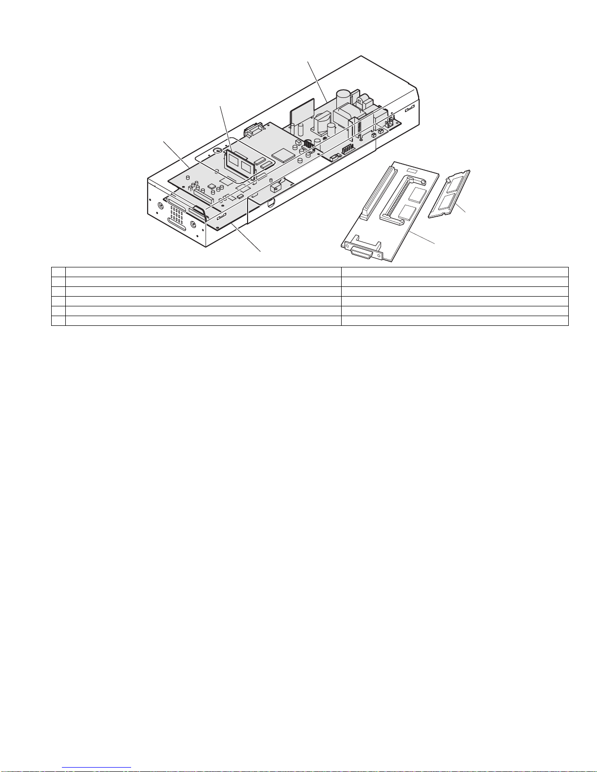
AR-FX12 EXTERNAL VIEWS AND INTERNAL STRUCTURES 4-2
2. FAX mode (Condition setting screen)
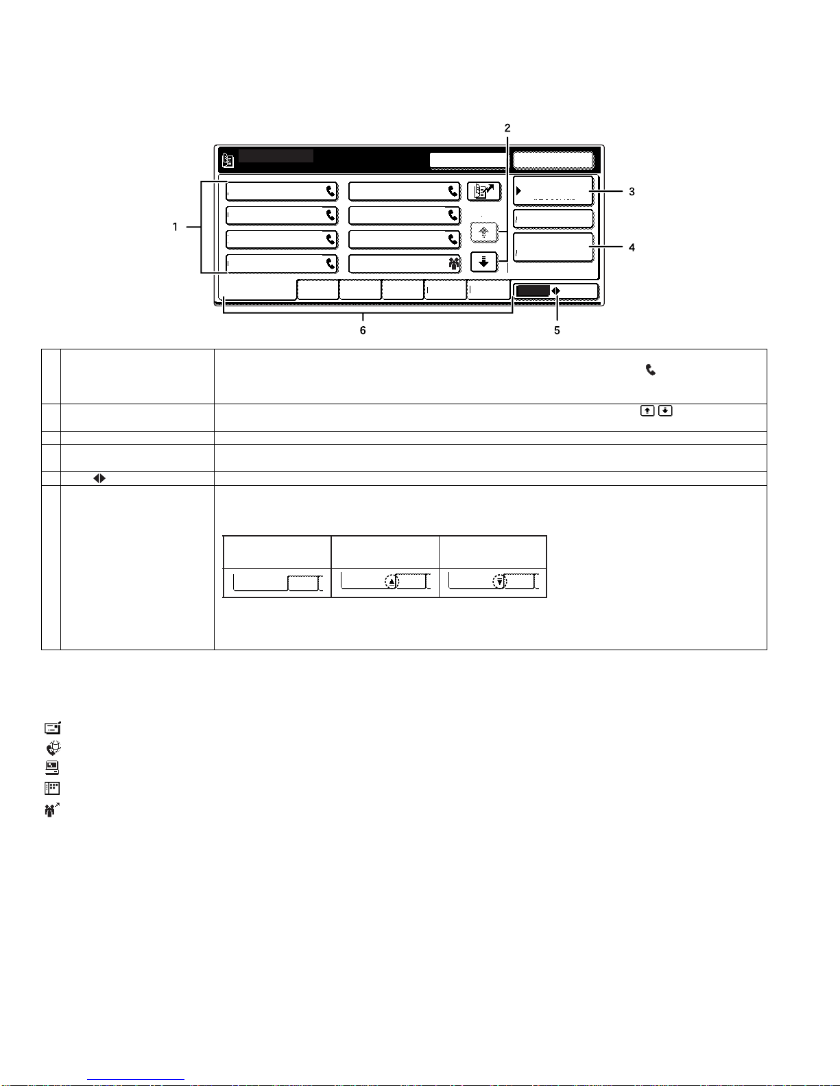
The condition settings screen of fax mode is displayed by pressing the [IMAGE SEND] key while the document filing mode (printer mode), copy mode,
or job status screen appears in the touch panel. In the explanations that follow, it is assumed that the initial screen that appears after pressing the
[IMAGE SEND] key is the condition settings screen (shown below). If you have set the display to show the address book screen (following page) when
the [IMAGE SEND] key is pressed, touch the [CONDITION SETTINGS] key in the address book screen to display the condition settings screen.
"Default display settings" in the key operator programs can be used to select whether the condition settings screen (below) appears or the address
book screen (next page) appears when the [IMAGE SEND] key is pressed.
•When the network scanner option is installed, you can select whether the "E-MAIL/FTP" screen or the "INTERNET FAX" screen appears when the
[IMAGE SEND] key is pressed (the selection is made in the key operator programs).
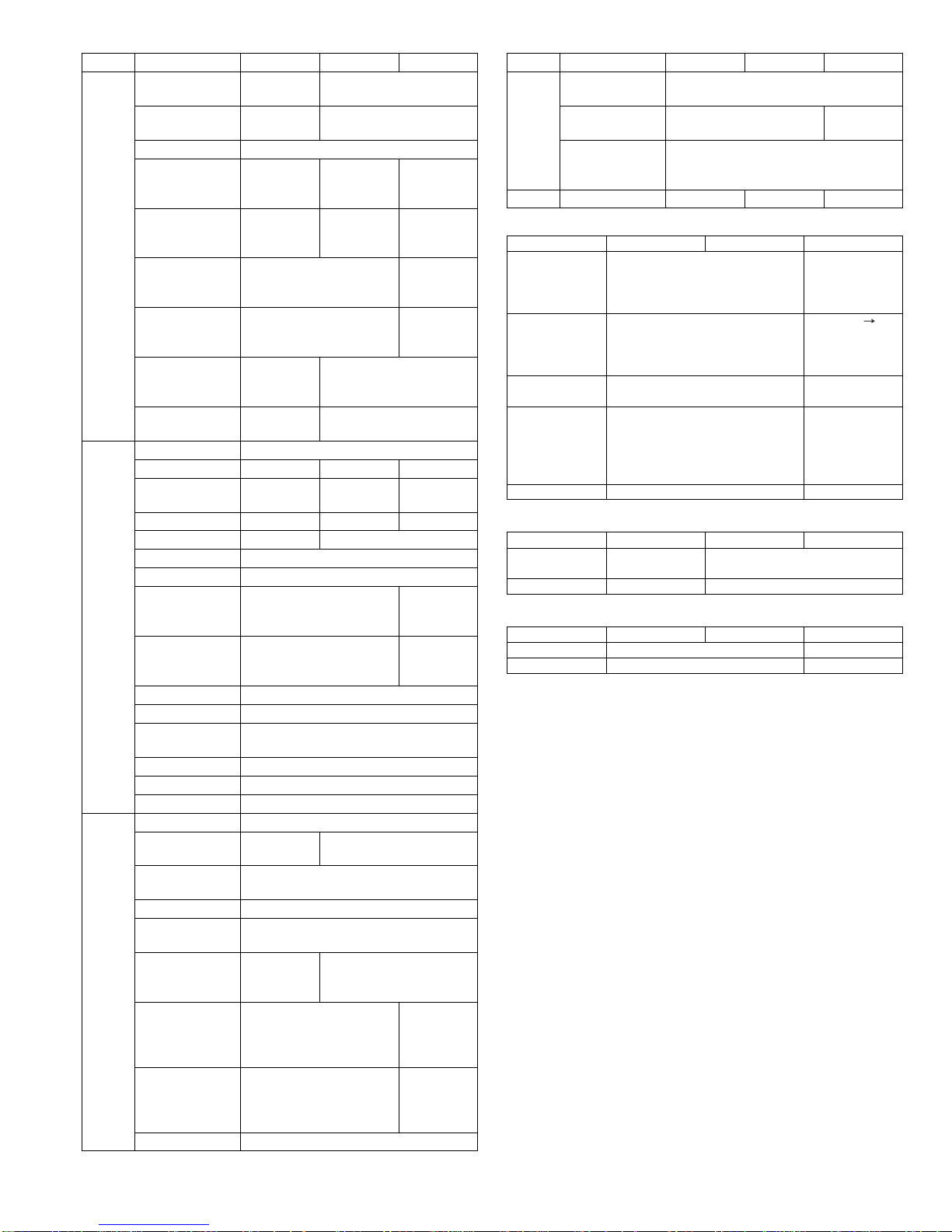
A. Condition setting screen
The display is initially set (factory setting) to show the following condition setting screen as the initial screen.
* Can only be used on the AR-M355N/AR-M455N. The AR-M355U/AR-M455U models do not have this function.
1 Message display Messages appear here to indicate the current status of the machine. The icon at left indicates fax mode.
2 [MODE SWITCH] key Use this key when the network scanner option is installed to switch between the "E-MAIL/FTP" and "INTERNET
FAX" screens
3[ ] key (Speed dial key) When a one-touch dial key or group key is stored in the address book, the machine automatically assigns it a 3-digit
number. This key and the Speed Dial number can be used to abbreviate the transmission procedure.
4 [SPEAKER] key Touch the [SPEAKER] key to dial and transmit a fax manually.
During dialing it changes into the [PAUSE] key, and after pressing the [SUB ADDRESS] key it changes into the
[SPACE] key.
5 [RESEND] key Touch this key to redial the number most recently dialed with the numeric keys or a one-touch dial key. After dialing,
this key changes into the [NEXT ADDRESS] key.
6 [ADDRESS BOOK] key Touch this key to display the address book screen (next page). Touch this key when you want to use an auto-dial
number (one-touch dialing or group dialing).
7 [ADDRESS REVIEW] key When performing a broadcast transmission, touch this key to check your selected destinations. The selected
destinations will appear and any unneeded destinations can be deleted.
8 [SPECIAL MODES] key Touch this key to select one of the following special functions:
•Edge erase •Dual page scan •Timer transmission •2in1 •Card shot •Job build mode •Polling •Memory box •Program
•Transaction report
9 [FILE] key* Touch this key to store a document image that you are transmitting in the hard disk (this includes selecting a user
name, file name, and location).
10 [QUICK FILE] key* Touch this key to store a document image that you are transmitting in the temporary storage folder.
11 Memory and reception mode
display This shows the amount of fax memory that is free and the currently selected reception mode.
12 [SUB ADDRESS] key Touch this key to enter a sub-address and passcode when using F-code transmission.
13 Two-sided scanning icon
display Icons appear here when you touch the [ORIGINAL] key and select two-sided scanning. The icons can be touched to
open function selection screens.
14 [ORIGINAL] key Touch this key when you wish to manually set the size of the original to be scanned or scan both sides of the
original.
15 [RESOLUTION] key Touch this key to change the resolution setting for the original to be scanned. The selected resolution setting will be
highlighted above the key. The initial factory setting is [STANDARD].
16 [EXPOSURE] key Touch this key to change the exposure setting for the original to be scanned. The selected exposure setting will be
highlighted above the key. The initial factory setting is AUTO.
17 Special mode icon display When a special mode such as polling or dual page scan is selected, a special mode icon appears here.
ADDRESS BOOK
AUTO
READY TO SEND.
ORIGINAL
STANDARD
RESOLUTION
AUTO
EXPOSURE
ADDRESS REVIEW
SPECIAL MODES
FILE
RESEND
SPEAKER
SUB ADDRESS
FAX
MODE SWITCH
QUICK FILE
AUTO RECEPTION
FAX MEMORY:100%
[04]ETERNALVIEWS.fm 2 ページ 2004年10月26日 火曜日 午後3時42分

AR-FX12 EXTERNAL VIEWS AND INTERNAL STRUCTURES 4-3
B. Address book screen (alphabetically ordered)
The screen below appears initially when the address book is set as the initial screen using "Default display settings" in the key operator programs.
•The screen below is the alphabetical index screen. You can also have the user index screen appear initially.
•The screen appears as shown below when the network scanner option is not installed.
NOTE
When the network scanner option is installed and a destination other than a fax numbers is stored in a one-touch key, one of the following icons will
appear.
: Scan to E-mail destination
: Internet fax destination
: Scan to FTP destination
: Scan to Desktop destination
: Multiple destinations (Scan to E-mail, fax, etc.)
1 One-touch key display This shows the one-touch keys that have been stored on the selected "index card". The key type is indicated by
the icon at the right. One-touch keys in which a fax number is stored are indicated by a " " icon.
The display is initially set to show 6 keys. This can be changed to 8 or 12 using the key operator program.
Display illustrations in this manual show the display set to eight keys.
2 Display switching keys When more one-touch keys are stored than can be displayed in one screen, touch the " " keys to change
screens.
3 [CONDITION SETTINGS] key This displays the condition settings screen (previous page), which is used to set various conditions.
4 [GLOBAL ADDRESS
SEARCH] key Touch this key to search for a fax number on an LDAP server.
5 [ABC GROUP] key Touch this key to switch between the alphabetical index and the group index.
6 Index keys One-touch key destinations are stored on each of these index cards (alphabetical index or group index). Each time
the selected tab is touched, the key display order changes from the order of storing (the initial display order), to
ascending order, to descending order. As this is done, the icon on the tab indicates the current display order.
Group indexes make it possible to store one-touch keys by group with an assigned name for easy reference. This
is done with the custom settings.
Frequently used onetouch key destinations can be stored on the FREQUENT USE card for convenient access.
A
FREQUENT USE ABCD EFGHI JKLMN OPQRST UVWXYZ ABC GROUP
B
C D
E F
GH
CONDITION
SETTINGS
READY TO SEND.
ADDRESS REVIEW
RESEND
SPEAKER
GLOBAL
ADDRESS SEARCH
1/2
Storing or order
(initially selected) Ascending order Descending order
FREQUENT USE ABCD FREQUENT USE ABCD FREQUENT USE ABCD
[04]ETERNALVIEWS.fm 3 ページ 2004年10月26日 火曜日 午後3時42分

AR-FX12 EXTERNAL VIEWS AND INTERNAL STRUCTURES 4-4
3. PWB
1 Modem control PWB FAX communication control
2 FAX FLASH ROM PWB FAX control program
3 FAX power PWB Supplies power to the FAX unit.
4 TEL/LIU PWB TEL line communication control
5 FAX I/F PWB (Installed to the machine side) Connection between FAX and MFP controller
6 FAX extended memory (Installed to FAX I/F PWB) <AR-MM9>
1
2
3
5
6
4
[04]ETERNALVIEWS.fm 4 ページ 2004年10月26日 火曜日 午後3時42分

AR-FX12 UNPACKING AND INSTALLATION 5-1
[5] UNPACKING AND INSTALLATION
<Before installation>
•For installation of AR-FX12, the control PWB unit and the scanner unit
must have been installed.
•Start installation after checking that the COMMUNICATION indictor on
the operation panel is neither lit nor blinking.
Then remove the power plug of the main unit from the outlet.
<1>Remove the scanner cable from the control PWB unit.
<2>Remove the five screws that secure the control PWB unit to the main
unit.
<3>Hold the two grips and pull out the control PWB unit until it is stopped
by the stopper.
<4>Remove the connector of the flat cable.
<5>While unlocking the stopper with your finger, pull the control PWB
unit to remove it from the main unit.
Remove the two screws that secure the FAX I/F cover of the control
PWB unit and remove the FAX I/F cover.
<Procedure for mounting additional memory (AR-MM9)>
* If mounting of additional memory is not needed, proceed to step 5.
Mount the additional memory to the socket located on the back side
of the interface PWB unit.
Connect the fax interface PWB unit to the fax interface PWB
connector (100 pins) of the control PWB unit and secure it with two
screws C.
<1>Reattach the control PWB unit to the main unit.
<2>Connect the flat cable that has been removed in step 2)-<4> to the
connector.
<3>Push the control PWB unit into the main unit and secure it with the
five screws.
1)Turn off the power switch of the main unit.
2)Pull out the control PWB unit.
3)Remove the FAX I/F cover.
4)Mount the additional memory.
5)Attach the fax interface PWB unit.
6)Reattach the control PWB unit.
[05]UNPACKINGANDINSTALLATION.fm 1 ページ 2004年10月26日 火曜日 午後3時43分

AR-FX12 UNPACKING AND INSTALLATION 5-2
<1>Secure screw A to the rack.
<2>Fit the positioning hole located on the side facing fax box unit to
screw A, slide the fax box unit toward the rack, and secure the rack
and the fax box unit using two screws B.
<1>Ensure that the fax power switch is set to “OFF”.
<2>Remove the screw from the connector cover for connection of the fax
power supply connector of the main unit and remove the connector
cover.
<3>Connect the fax power supply connector to the connector of the main
unit.
<4>Secure the connector by lightening the three screws on the
connector.
Connect the fax interface cable to the fax box unit and the control
PWB unit.
Connect the scanner cable that has been removed in step 2.
Insert the power plug of the main unit to the outlet and turn on the
power switch of the main unit and the fax power switch of the box
unit.
•Be sure to set the destination for the main unit before setting the
destination for the fax.
<1>Switch the operation panel to the copy mode and use the key
operation [P], [*], [C], and [*] to enter the simulation mode.
<2>Use the 10-key pad to enter [26] in the main code entry screen and
press the [START] key.
<3>The sub-code list is displayed. Use the 10-key pad to enter [6] and
press the [START] key.
<4>Select the desired destination from the destination list by entering
the number and press the [START] key.
When you press the [START] key, this machine will be rebooted and
will start with the setting of the selected destination for the main unit.
Example: To set the UK as the destination, select it from the
destination list by entering [7] and press the [START] key.
<1>Switch the operation panel to the copy mode and use the key
operation [P], [*], [C], and [*] to enter the simulation mode.
<2>Use the 10-key pad to enter [66] in the main code entry screen and
press the [START] key.
<3>Use the 10-key pad to enter [2] in the sub-code entry screen and
press the [START] key.
7)Attach the fax box unit.
8)Connect the fax power supply connector.
9)Connect the connector.
10)Turn on the power switches of the main unit.
11)Set the destination for the main unit.
12)Set the destination for the fax.
[05]UNPACKINGANDINSTALLATION.fm 2 ページ 2004年10月26日 火曜日 午後3時43分

AR-FX12 UNPACKING AND INSTALLATION 5-3
<4>Select the desired destination from the destination list (separate
table 1) by entering the number using the 10-key pad and press the
[START] key.
(For example, to set the UK as the destination, enter [10110100]
using the 10-key pad and then press the [START] key.
<5>Check the destination in the following screen. If the destination is
correct, enter [1] (YES) using the 10-key pad and press the [START]
key.
<6>Press the [CA] key.
* This machine will be rebooted and will start with the setting of the
selected destination for the fax.
Separate table 1: Setting value of destination for fax
•If an additional memory (AR-MM9) has been mounted, be sure to carry
out this step.
If no additional memory has been mounted, this step is not necessary.
<1>Switch the operation panel to the copy mode and use the key
operation [P], [*], [C], and [*] to enter the simulation mode.
<2>Use the 10-key pad to enter [66] in the main code entry screen and
press the [START] key.
<3>Use the 10-key pad to enter [10] in the sub-code entry screen and
press the [START] key.
<4>Use the 10-key pad to enter [1] in the submenu screen and press the
[START] key.
<5>The screen shown below is displayed and memory clear operation is
executed.
<6>After several minutes, memory clear operation will be completed and
then this machine will be automatically rebooted.
Connect the line cable to the fax box unit.
As shown in the figure, insert the FAX cable terminal (with the core
attached) into the FAX box unit.
Destination FAX Software SW No.1 - 8
U.S.A 10110101
AUSTRALIA 00001001
NEWZEALAND 01111110
U.K. 10110100
FRANCE 00111101
GERMANY 00000100
SWEDEN 10100101
13)Clear the image memory.
14)Connect the line cable to the fax box unit.
[05]UNPACKINGANDINSTALLATION.fm 3 ページ 2004年10月26日 火曜日 午後3時43分

AR-FX12 SIMULATIONS, FAX SOFTWARE SWITCH 6-1
[6] SIMULATIONS, FAX SOFTWARE SWITCH
1. Entering the simulation mode
a. Normal mode
Enter the copy mode and perform the following procedures.
[P] [*] [C] [*] [Main code] [START] [Sub code] [START]
b. FAX mode
Enter the copy mode and perform the following procedures.
[9] [*] [8] [#] [7]
2. Switching the simulation mode
Press [USER SETTING] to return to the code entry screen.
3. Canceling the simulation mode
Press CA key to cancel the simulation mode.
4. Simulation list
Code Function (Content) Purpose Section Item
Main Sub
22 5 Used to check the ROM version of each unit (section). Other Software
6 Used to print the list of adjustments and setup data
(simulations, FAX soft switches, counters). Adjustment, setup,
operation data output,
check (print)
Data Setup,
adjustment
data
11 Used to check the use frequency of FAX. (send/receive)
(Only when FAX is installed.) Adjustment, setup,
operation data output,
check (display)
FAX Data
23 2 Jam/Trouble data print
24 10 Used to clear the FAX counter. (After completion of
maintenance, this counter must be cleared.)
(Only when FAX is installed.)
Data clear FAX Counter
46 12 Used to adjust the print density in the FAX mode (all modes).
An adjustment with this simulation affects all the copy density
adjustment values. (Only when FAX is installed)
Adjustment Picture
quality
13 Used to adjust the print density in the FAX mode
(Standard mode). (Only when FAX is installed.) Adjustment Picture
quality
14 Used to adjust the print density in the FAX mode
(Fine mode). (Only when FAX is installed.) Adjustment Picture
quality
15 Used to adjust the print density in the FAX mode
(Super Fine mode). (Only when FAX is installed.) Adjustment Picture
quality
16 Used to adjust the print density in the FAX mode
(Ultra Fine mode). (Only when FAX is installed.) Adjustment Picture
quality
56 1 Data transfer
61 3 Used to adjust laser power (absolute value) in the FAX
reception mode. (Only when FAX is installed.) Adjustment Operation
[06]SIMULATIONS ・FAXSOFTWARESWITCH.fm 1ページ 2004年10月26日 火曜日 午後3時44分

AR-FX12 SIMULATIONS, FAX SOFTWARE SWITCH 6-2
66 1 Used to set the FAX soft switch function. (Used to utilize the
FAX soft switch function.) Setup FAX
2 Used to set the FAX soft switch setup to the default.
(Except for the adjustment values) Data clear FAX Data
3 Used to check the operations of FAX PWB memory
(read/write). (This adjustment is required when replacing the
PWB with a new one.)
Operation test, check FAX Data
4 Used to check the operations of data signal output in the FAX
data output mode.
(Used to check the MODEM operation.)
Send level Max. (Only when FAX is installed.)
Operation test, check FAX Operation
5 Used to check the operations of data signal output in the FAX
data output mode.
(Used to check the MODEM operation.)Signals are sent in the
send level set with the soft switch. (Only when FAX is installed.)
Operation test, check FAX Operation
6 Used to print the confidential password.
(Used when the confidential password is forgotten.)
(Only when FAX is installed.)
User data output, check
(display, print) FAX Data
7 Used to print the image memory data (memory send, receive).
(Only when FAX is installed.) User data output, check
(display, print) FAX Data
8 Used to check the output operation of the FAX sound signals.
(Sound output IC operation check) Send level Max.
(Only when FAX is installed.)
Operation test, check FAX Operation
9 Used to check the output operation of the FAX sound signals.
(Sound output IC operation check)
(Only when FAX is installed.)
Operation test, check FAX Operation
10 Used to clear all data of image memory
(memory send, receive). Confidential data are also cleared.
(Only when FAX is installed.)
User data output, check
(display, print) FAX Data
11 Used to check the output operation of FAX G3 mode 300BPS.
(Used to check the MODEM operation.)
Send level 0dB (Max.) (Only when FAX is installed.)
Operation test, check FAX Operation
12 Used to check the output operation of FAX G3 mode 300BPS.
(Used to check the MODEM operation.) Signals are sent in the
send level set with the soft switch. (Only when FAX is installed.)
Operation test, check FAX Operation
13 Used to enter (set) the number for the FAX dial signal output
test.
(The dial number signal set with this simulation is outputted in
the dial signal output test with SIM 66-14~16)
(Only when FAX is installed.)
Setup FAX Data
14 Used to set the make time in the FAX pulse dial mode (10PPS)
and to test the dial signal output.
(The dial number signal set with SIM 66-13 is outputted.)
Used to check dialing troubles and the operation.
(Only when FAX is installed.)
Setup FAX Operation
15 Used to set the make time in the FAX pulse dial mode (20PPS)
and to test the dial signal output. (The dial number signal set
with SIM 66-13 is outputted.) Used to check dialing troubles
and the operation. (Only when FAX is installed.)
Setup FAX Operation
16 Used to test the dial signal (DTMF) output in the FAX tone dial
mode. (The dial number signal set with SIM 66-13 is outputted.)
The send level can be set to an optional level.
Dialing troubles and operation.(Only when FAX is installed.)
Setup FAX Operation
17 Used to test the dial signal (DTMF) output in the Fax tone dial
mode. Send level Max. Used to check the operation.
(Only when FAX is installed.)
Setup FAX Operation
18 Used to test the dial signal (DTMF) in the FAX tone dial mode.
The send level set with the soft switch is outputted. Used to
check the operation. (Only when FAX is installed.)
Setup FAX Operation
19 Used to backup the Address data into the flash Memory
(Option FAX memory:AR-MM9)
(Only when FAX is installed.)
Setup FAX Operation
20 Used to restore the backup data (SIM 66-19) to Address data.
(Only when FAX is installed.) Setup FAX Operation
Code Function (Content) Purpose Section Item
Main Sub
[06]SIMULATIONS ・FAXSOFTWARESWITCH.fm 2 ページ 2004年10月26日 火曜日 午後3時44分

AR-FX12 SIMULATIONS, FAX SOFTWARE SWITCH 6-3
66 21 Used to print the FAX information (registrations, communication
management, file management, system errors, protocol).
(Only when FAX is installed.)
Adjustment, setup,
operation data output,
check (display, print)
FAX Data
23 Used to download the FAX program.
(Only when FAX is installed.) Inhibited FAX
24 Used clear the FAST memory data.
(Only when FAX is installed.) Inhibited FAX
25 Used to register the FAX number for MODEM dial-in.
(Only when FAX is installed.) Inhibited FAX
26 Used to register the external telephone number for MODEM
dial-in. (Only when FAX is installed.) Inhibited FAX
27 Used to register the voice-warp transfer number.
(Only when FAX is installed.)(Voice-warp:Japan only) Inhibited FAX
29 Used to clear the Address data. Setup FAX Operation
30 Used to check TEL/LIU status change. Setup FAX Operation
31 Used to set the TEL/LIU status. Setup FAX Operation
32 Used to check received data. Inhibited FAX
33 Used to check signal detection. Inhibited FAX
34 Used to measure and display the communication time. Setup FAX Operation
35 Modem program rewriting.(Only when FAX is installed.) Operation test, check FAX Operation
36 Used to check I/F between MFPC and MDMC.
Check is made in the data line or the command line. Operation test, check FAX Operation
39 Registration of FAX destination FAX
42 Used to rewrite the program to the PIC installed in the FAX box.
To execute this simulation, FAX program writing must be
allowed. (Jumper and DIP switch which differ depending on the
model)
FAX
43 To execute this simulation, FAX program writing must be
allowed. (Jumper and DIP switch which differ depending on the
model)The adjustment value of PIC are changed and written.
The current setting is highlighted beside the item.
FAX
Code Function (Content) Purpose Section Item
Main Sub
[06]SIMULATIONS ・FAXSOFTWARESWITCH.fm 3 ページ 2004年10月26日 火曜日 午後3時44分

AR-FX12 SIMULATIONS, FAX SOFTWARE SWITCH 6-4
5. Detail of simulations
<List of display values>
Main code 22
22-5
Purpose Other
Function (Content) Used to check the ROM version of each unit
(section).
Section
Item Software
Operation/Procedure The version of each ROM is displayed.
S/N Engine section serial number
MFP MFP controller
(LANGUAGE) (Language version)
BOOT MFP controller boot ROM
FAX FAX controller
PCU PCU controller
SCANNER Scanner controller
FINISHER Finisher controller
SADDLE UNIT Saddle unit
LCC Side LCC
INSERTER Inserter
22-6
Purpose Adjustment, setup, operation data output, check
(print)
Function (Content) Used to print the list of adjustments and setup
data (simulations, FAX soft switches, counters).
Section
Item Data
Operation/Procedure The selected data is displayed on the right side
of the item.
0 TRAY SELECT auto only (no selection)
1 PRINT START
SIMULATION 22-5
ROM VERSION DATA DISPLAY.
S/N : 000000000
MFP : 1.00 (LANGUAGE : 1.00)
PCU : 1.00 BOOT : 1.00
SCANNER : 1.00 FAX : 1.00
FINISHER : 1.00
SADDLE UNIT : 1.00 LCC : 1.00
INSERTER : 1.00
SIMULATION 22-6
DATA PRINT MODE, SELECT SETTING,AND PRESS START.
0. TRAY SELECT :AUTO ONLY
1. PRINT START 1
SIMULATION 22-6
DATA PRINT MODE.. EXECUTING
0
When "1" is selected,
press [START] key. Press [CUSTOM SETTINGS] key
or [START] key
22-11
Purpose Adjustment, setup, operation data output, check
(display)
Function (Content) Used to check the use frequency of FAX.
(send/receive) (Only when FAX is installed.)
Section FAX
Item Data
Operation/Procedure The counter data below are displayed.
FAX SEND Number of times of FAX sending
FAX RECEIVE Number of times of FAX receiving
FAX OUTPUT FAX print quantity
SEND IMAGES Quantity of sending
SEND TIME Time for sending
RECEIVE TIME Time for receiving
SIMULATION 22-11
FAX COUNTER DATA DISPLAY.
FAX SEND : ******** FAX RECEIVE : ********
FAX OUTPUT : ********
SEND IMAGES : ******** SEND TIME : ********:**:**
RECEIVE TIME : ********:**:**
[06]SIMULATIONS ・FAXSOFTWARESWITCH.fm 4 ページ 2004年10月26日 火曜日 午後3時44分

AR-FX12 SIMULATIONS, FAX SOFTWARE SWITCH 6-5
<List of display values>
<List of set values>
Main code 23
23-2
Purpose
Function (Content) Jam/Trouble data print
Section
Item
Operation/Procedure The current selected data is displayed on the
side of the menu.
0 TRAY SELECT (Selection disabled)
1 PRINT START
SIMULATION 23-2
JAM/TOROUBLE DATA PRINT MODE. SELECT SETTING, AND
PRESS START.
0. TRAY SELECT :AUTO ONLY
1. PRINT START 1
When "1" is selected,
press [START] key
SIMULATION 23-2
JAM/TOROUBLE DATA PRINT MODE.. EXECUTING .
0.TRAY SELECT : 0
1
Press [CUSTOM SETTINGS] key
or [START] key
Main code 24
24-10
Purpose Data clear
Function (Content) Used to clear the FAX counter.
Section FAX
Item Counter
Operation/Procedure Select with 10 digit key pad and press START
key.
The procedure below is executed and the display
returns to the original state.
1: Counter is cleared 2: Not cleared
1 FAX SEND: Number of times of FAX sending
2 FAX RECEIVE: Number of times of FAX reception
3 FAX OUTPUT: FAX print quantity
4 SEND IMAGES: Sending quantity
5 SEND TIME: Time for sending
6 RECEIVE TIME: Time for reception
1
SIMULATION 24-10
FAX SEND COUNTER DATA CLEAR.
ARE YOU SURE?
1. YES
2. NO
1
SIMULATION 24-10
FAX COUNTER DATA CLEAR. SELECT 1-6, AND PRESS START.
1. FAX SEND
2. FAX RECEIVED
3. FAX OUTPUT
4. SEND IMAGES
5. SEND TIME
6. RECEIVE TIME
Press [START] key. Press [CUSTOM SETTINGS] key
or [START] key
[06]SIMULATIONS ・FAXSOFTWARESWITCH.fm 5 ページ 2004年10月26日 火曜日 午後3時44分

AR-FX12 SIMULATIONS, FAX SOFTWARE SWITCH 6-6
<List of set values 1>
<List of display values 1>
<List of set values 2>
Main code 46
46-12
Purpose Adjustment
Function (Content) Used to adjust the print density in the FAX mode
(all modes). An adjustment with this simulation
affects all the reading density adjustment values.
(Only when FAX is installed)
Section
Item Picture quality
Operation/Procedure The exposure mode to be set is selected.
(FAX auto adjustment)
1) The current set value is highlighted on the
right side of each item. In this screen, be sure
to select "1: COPY START." (Set value: 1)
2) Set the exposure level with 10 digit key pad.
Press P to store the set value.
(Default: 50, set range: 0 - 99)
3) Press START, and copying is started and the
set value is stored. (Display value 1)
4) Select a paper feed tray. (Set value 2)
SIMULATION 46-12
EXP. LEVEL SETUP FAX (AUTO SET). SELECT 0-2, AND PRESS START.
0. TRAY SELECT 1. COPY START
2. FAX EXP. LEVEL 1
SIMULATION 46-12
EXP. LEVEL SETUP FAX (AUTO SET),INPUT VALUE 0-99, AND PRESS
START.
2. FAX EXP. LEVEL 50
SIMULATION 46-12
EXP. LEVEL SETUP FAX (AUTO SET). SELECT 1-5, AND PRESS START.
(FEED TRAY)
1. TRAY1 2. TRAY2 3. TRAY3 4. TRAY4 5.BPT 1
SIMULATION 46-12
EXP. LEVEL SETUP FAX (AUTO SET). NOW PRINTING.
1
50
Select other than 0 - 1,
and press [START] key.
Select 1, and
press [START] key.
Select 0, and
press [START] key.
Press [START] key.
Press [CUSTOM SETTINGS] key
Or copying is terminated.
Press [START] key or
0 Paper feed tray selection
1 Copy start (Default)
2 FAX mode exposure setup
Normal display “NOW PRINTING”
ERROR display DOOR OPEN.
JAM
PAPER EMPTY.
1TRAY1
2TRAY2
3TRAY3
4TRAY4
5 Manual feed
[06]SIMULATIONS ・FAXSOFTWARESWITCH.fm 6 ページ 2004年10月26日 火曜日 午後3時44分

AR-FX12 SIMULATIONS, FAX SOFTWARE SWITCH 6-7
<List of set values 1>
<List of display values 1>
<List of set values 2>
For the above +20, the machine enters the duplex mode (DS), making
duplex copy.
<List of set values 3>
46-13
Purpose Adjustment
Function (Content) Used to adjust the reading density in the FAX
mode (Standard mode).
(Only when FAX is installed.)
Section
Item Picture quality
Operation/Procedure The exposure mode to be set is selected.
(FAX Standard mode individual adjustment)
1) The current set value is highlighted on the
right side of each item. In this screen, be sure
to select "1: PRINT START." (Set value: 1)
2) Set the exposure level with 10 digit key pad.
Press P to store the set value.
(Default: 50, set range: 0 - 99)
3) Press START, and copying is started and the
set value is stored. (Display value 1)
4) Select a paper feed tray. (Set value 2)
5) Select an exposure level. (Set value 3)
SIMULATION 46-13
EXP. LEVEL SETUP FAX(NORMAL). SELECT 0-8, AND PRESS START.
0. TRAY SELECT 1. PRINT START
2. EXP LEVEL
3. AUTO 4. 1.0 5. 2.0
6. 3.0 7. 4.0 8. 5.0
1
SIMULATION 46-13
EXP. LEVEL SETUP FAX(NORMAL),INPUT VALUE 0-99, AND PRESS START.
4. 1.0 50
SIMULATION 46-13
EXP. LEVEL SETUP FAX(NORMAL). SELECT 1-5, AND PRESS START.
(FEED TRAY)
1. TRAY1 2. TRAY2 3. TRAY3 4. TRAY4
5. BPT
(ABOVE +20: DSPF MODE)
1
SIMULATION 46-13
EXP. LEVEL SETUP FAX(NORMAL). NOW PRINTING.
SIMULATION 46-13
EXP. LEVEL SETUP FAX(NORMAL). SELECT 3-8, AND PRESS START.
(EXP. LEVEL SELECT)
3. AUTO 4. 1.0 5. 2.0
6. 3.0 7. 4.0 8. 5.0 1
50
1
1
50 50
50
50 50
Select other than 0 - 2,
and press [START] key.
Select 1, and
press [START] key.
Select 2, and
press [START] key.
Select 0, and
press [START] key.
Press [START] key.
Press [CUSTOM SETTINGS] key
Or copying is terminated.
Press [CUSTOM SETTINGS] key
Press [START] key or
Press [CUSTOM SETTINGS] key
Press [START] key or
0 Paper feed tray selection
1 Print start (Default)
2 Exposure level selection
3Auto
4 Exposure level 1
5 Exposure level 2
6 Exposure level 3
7 Exposure level 4
8 Exposure level 5
Normal display “NOW PRINTING”
ERROR display DOOR OPEN.
JAM
PAPER EMPTY.
1TRAY1
2TRAY2
3TRAY3
4TRAY4
5 Manual feed
3Auto
4 Exposure level 1
5 Exposure level 2
6 Exposure level 3
7 Exposure level 4
8 Exposure level 5
[06]SIMULATIONS ・FAXSOFTWARESWITCH.fm 7 ページ 2004年10月26日 火曜日 午後3時44分

AR-FX12 SIMULATIONS, FAX SOFTWARE SWITCH 6-8
<List of set values 1>
<List of display values 1>
<List of set values 2>
<List of set values 3>
46-14
Purpose Adjustment
Function (Content) Used to adjust the reading density in the FAX
mode (Fine mode). (Only when FAX is installed.)
Section
Item Picture quality
Operation/Procedure The exposure mode to be set is selected.
(FAX Fine mode individual adjustment)
1) The current set value is highlighted on the
right side of each item. In this screen, be sure
to select "1: PRINT START." (Set value: 1)
2) Set the exposure level with 10 digit key pad.
Press P to store the set value.
(Default: 50, set range: 0 - 99)
3) Press START, and copying is started and the
set value is stored. (Display value 1)
4) Select a paper feed tray. (Set value 2)
5) Select an exposure level. (Set value 3)
SIMULATION 46-14
EXP. LEVEL SETUP FAX(FINE). SELECT 0-14, AND PRESS START.
0. TRAY SELECT 1. PRINT START
2. EXP LEVEL
3. AUTO 4. 1.0 5. 2.0
6. 3.0 7. 4.0 8. 5.0
9. AUTO(H) 10. 1.0(H) 11. 2.0(H)
12. 3.0(H) 13. 4.0(H) 14. 5.0(H)
1
SIMULATION 46-14
EXP. LEVEL SETUP FAX(FINE),INPUT VALUE 0-99, AND PRESS START.
4. 1.0 50
SIMULATION 46-14
EXP. LEVEL SETUP FAX(FINE). SELECT 1-5, AND PRESS START.
(FEED TRAY)
1. TRAY1 2. TRAY2 3. TRAY3 4. TRAY4
5. BPT
1
SIMULATION 46-14
EXP. LEVEL SETUP FAX(FINE). NOW PRINTING.
SIMULATION 46-14
EXP. LEVEL SETUP FAX(FINE). SELECT 3-14, AND PRESS START.
(EXP. LEVEL SELECT)
3. AUTO 4. 1.0 5. 2.0
6. 3.0 7. 4.0 8. 5.0
9. AUTO(H) 10. 1.0(H) 11. 2.0(H)
12. 3.0(H) 13. 4.0(H) 14. 5.0(H)
1
50
50
1
1
50
50
50
50
50
50
50
50
50
50
Press [CUSTOM SETTINGS] key.
Select other than 0 - 2,
and press [START] key.
Select 1, and
press [START] key.
Select 2, and
press [START] key.
Select 0, and
press [START] key.
Press [START] key.
Press [START] key or
press [CUSTOME SETTINGS] key.
Press [START] key or
press [CUSTOME SETTINGS] key.
Press [CUSTOM SETTINGS] key.
Or copying is terminated.
0 Paper feed selection
1 Print start (Default)
2 Exposure level selection
3Auto
4 Exposure level 1
5 Exposure level 2
6 Exposure level 3
7 Exposure level 4
8 Exposure level 5
<Half tone>
9Auto
10 Exposure level 1
11 Exposure level 2
12 Exposure level 3
13 Exposure level 4
14 Exposure level 5
Normal display “NOW PRINTING”
ERROR display DOOR OPEN.
JAM
PAPER EMPTY.
1TRAY1
2TRAY2
3TRAY3
4TRAY4
5 Manual feed
3Auto
4 Exposure level 1
5 Exposure level 2
6 Exposure level 3
7 Exposure level 4
8 Exposure level 5
<Half tone>
9Auto
10 Exposure level 1
11 Exposure level 2
12 Exposure level 3
13 Exposure level 4
14 Exposure level 5
[06]SIMULATIONS ・FAXSOFTWARESWITCH.fm 8 ページ 2004年10月26日 火曜日 午後3時44分
Other manuals for AR-FX12
2
This manual suits for next models
1
Table of contents
Other Sharp Fax Machine manuals

Sharp
Sharp FO-2150CM User manual

Sharp
Sharp UX-B700 User manual

Sharp
Sharp FO-1470 User manual

Sharp
Sharp FO-IS115N User manual

Sharp
Sharp FO IS125N - B/W Laser - All-in-One User manual

Sharp
Sharp FO-50 User manual

Sharp
Sharp UX-D50 User manual

Sharp
Sharp FO-175 User manual

Sharp
Sharp FO-475 User manual

Sharp
Sharp UX-CL 220 User manual

Sharp
Sharp FO-165 User manual

Sharp
Sharp FO-5700U User manual

Sharp
Sharp FO-165 User manual

Sharp
Sharp FO-155 User manual

Sharp
Sharp FO-5500 User manual

Sharp
Sharp FO-2970M User manual

Sharp
Sharp FO-IS115N User manual

Sharp
Sharp UX-P880TH User manual

Sharp
Sharp FO-220 User manual

Sharp
Sharp UX-178 User manual