Sharp FO-3150 User manual

FO-3150U/C
No. 00ZFO3150USME
Parts marked with " " is important for maintaining the safety of the set. Be sure to replace these parts with specified ones for maintain-
ing the safety and performance of the set.
This document has been published to be used
for after sales service only.
The contents are subject to change without notice.
SHARP CORPORATION
SERVICE MANUAL
Laser Wave Length : 780 ±15 nm
Laser Pulse Times : (13.95 ±3 µs)/7mm
Laser Output Power : 0.3 mW ±0.05mW
CAUTION
This laser facsimile is a class 1 laser product that complies with 21CFR 1040.10 and 1040.11 of the CDRH or IEC60825-1 standard.
This means that this machine does not produce a hazardous laser radiation. The use of controls, adjustments or performance of
procedures other than those specified herein may result in hazardous radiation exposure.
This laser radiation is not a danger to the skin, but when an exact focusing of the laser beam is achieved on the eyes retina, there is
danger of spot damage to the retina.
The following cautions must be observed to avoid exposure of the laser beam to your eyes at the time of servicing.
1) When a problem in the laser optical unit has occurred, the whole optical unit must be exchanged as a unit, not an individual part.
2) Do not look into the machine with the main switch turned on after removing the toner/developer unit and drum cartridge.
3) Do not look into the laser beam exposure slit of the laser optical unit with the connector connected when removing and installing
the optical system.
4) The cover of Laser Printer Unit contains the safety interlock switch.
Do not defeat the safety interlock by inserting wedges or other items into the switch slot.
FACSIMILE
FO-3150
MODEL
MODEL SELECTION CODE DESTINATION
FO-3150 U
U.S.A.
FO-3150 C
Canada

FO-3150U/C
CONTENTS
CHAPTER 1. GENERAL DESCRIPTION
[1] Specifications . . . . . . . . . . . . . . . . . . . . . . . . . . . . . . . . . . . . . . . . . . . . . . . . . . . . . . . . . . . . . . . . . . 1-1
[2] Operation panel . . . . . . . . . . . . . . . . . . . . . . . . . . . . . . . . . . . . . . . . . . . . . . . . . . . . . . . . . . . . . . . . 1-2
[3] Transmittable documents . . . . . . . . . . . . . . . . . . . . . . . . . . . . . . . . . . . . . . . . . . . . . . . . . . . . . . . . . 1-3
[4] Installation . . . . . . . . . . . . . . . . . . . . . . . . . . . . . . . . . . . . . . . . . . . . . . . . . . . . . . . . . . . . . . . . . . . . 1-4
[5] Maintenance . . . . . . . . . . . . . . . . . . . . . . . . . . . . . . . . . . . . . . . . . . . . . . . . . . . . . . . . . . . . . . . . . . 1-11
[6] Troubleshooting . . . . . . . . . . . . . . . . . . . . . . . . . . . . . . . . . . . . . . . . . . . . . . . . . . . . . . . . . . . . . . . 1-13
[7] Quick reference guide . . . . . . . . . . . . . . . . . . . . . . . . . . . . . . . . . . . . . . . . . . . . . . . . . . . . . . . . . . 1-14
CHAPTER 2. ADJUSTMENTS
[1] Adjustments . . . . . . . . . . . . . . . . . . . . . . . . . . . . . . . . . . . . . . . . . . . . . . . . . . . . . . . . . . . . . . . . . . . 2-1
[2] Diagnostics and service soft switches . . . . . . . . . . . . . . . . . . . . . . . . . . . . . . . . . . . . . . . . . . . . . . . 2-4
[3] Troubleshooting . . . . . . . . . . . . . . . . . . . . . . . . . . . . . . . . . . . . . . . . . . . . . . . . . . . . . . . . . . . . . . . 2-27
[4] Error code table . . . . . . . . . . . . . . . . . . . . . . . . . . . . . . . . . . . . . . . . . . . . . . . . . . . . . . . . . . . . . . . 2-28
CHAPTER 3. MECHANICAL DESCRIPTION
[1] Mechanical description . . . . . . . . . . . . . . . . . . . . . . . . . . . . . . . . . . . . . . . . . . . . . . . . . . . . . . . . . . . 3-1
[2] Disassembly, assembly, lubrication . . . . . . . . . . . . . . . . . . . . . . . . . . . . . . . . . . . . . . . . . . . . . . . . 3-11
CHAPTER 4. DIAGRAMS
[1] Block diagram . . . . . . . . . . . . . . . . . . . . . . . . . . . . . . . . . . . . . . . . . . . . . . . . . . . . . . . . . . . . . . . . . 4-1
[2] Wiring diagram . . . . . . . . . . . . . . . . . . . . . . . . . . . . . . . . . . . . . . . . . . . . . . . . . . . . . . . . . . . . . . . . . 4-2
[3] Point-to-point diagram and connector signal name . . . . . . . . . . . . . . . . . . . . . . . . . . . . . . . . . . . . . 4-3
CHAPTER 5. CIRCUIT DESCRIPTION
[1] Circuit description . . . . . . . . . . . . . . . . . . . . . . . . . . . . . . . . . . . . . . . . . . . . . . . . . . . . . . . . . . . . . . . 5-1
[2] Circuit description of control PWB . . . . . . . . . . . . . . . . . . . . . . . . . . . . . . . . . . . . . . . . . . . . . . . . . . 5-2
[3] Circuit description of printer PWB (PCU) . . . . . . . . . . . . . . . . . . . . . . . . . . . . . . . . . . . . . . . . . . . . 5-12
[4] Circuit description of TEL/LIU and Hook SW PWB . . . . . . . . . . . . . . . . . . . . . . . . . . . . . . . . . . . . 5-22
[5] Circuit description of power supply PWB . . . . . . . . . . . . . . . . . . . . . . . . . . . . . . . . . . . . . . . . . . . . 5-24
[6] Circuit description of CIS UNIT . . . . . . . . . . . . . . . . . . . . . . . . . . . . . . . . . . . . . . . . . . . . . . . . . . . 5-25
CHAPTER 6. CIRCUIT SCHEMATICS AND PARTS LAYOUT
[1] Control PWB circuit . . . . . . . . . . . . . . . . . . . . . . . . . . . . . . . . . . . . . . . . . . . . . . . . . . . . . . . . . . . . . 6-1
[2] TEL/LIU and Hook SW PWB circuit . . . . . . . . . . . . . . . . . . . . . . . . . . . . . . . . . . . . . . . . . . . . . . . . 6-11
[3] Printer PWB circuit . . . . . . . . . . . . . . . . . . . . . . . . . . . . . . . . . . . . . . . . . . . . . . . . . . . . . . . . . . . . . 6-16
[4] Power supply PWB circuit . . . . . . . . . . . . . . . . . . . . . . . . . . . . . . . . . . . . . . . . . . . . . . . . . . . . . . . 6-19
[5] Operation panel PWB circuit . . . . . . . . . . . . . . . . . . . . . . . . . . . . . . . . . . . . . . . . . . . . . . . . . . . . . 6-21
CHAPTER 7. OPERATION FLOWCHART
[1] Protocol . . . . . . . . . . . . . . . . . . . . . . . . . . . . . . . . . . . . . . . . . . . . . . . . . . . . . . . . . . . . . . . . . . . . . . 7-1
[2] Power on sequence . . . . . . . . . . . . . . . . . . . . . . . . . . . . . . . . . . . . . . . . . . . . . . . . . . . . . . . . . . . . . 7-2
CHAPTER 8. OTHERS
[1] Service Tools . . . . . . . . . . . . . . . . . . . . . . . . . . . . . . . . . . . . . . . . . . . . . . . . . . . . . . . . . . . . . . . . . . 8-1
[2] Rewriting the Flash ROM . . . . . . . . . . . . . . . . . . . . . . . . . . . . . . . . . . . . . . . . . . . . . . . . . . . . . . . . . 8-4
PARTS GUIDE

1 – 1
FO-3150U/C
CHAPTER 1. GENERAL DESCRIPTION
[1] Specifications
1 GENERAL
Automatic dialing Rapid Key Dialing: 10 numbers
Speed Dialing: 99 numbers
Memory size* 1.8 MB (approx. 100 average pages)
Modem speed 14,400 bps with auto fallback to lower speeds.
Transmission time* Approx. 6 seconds (only when ECM is on)
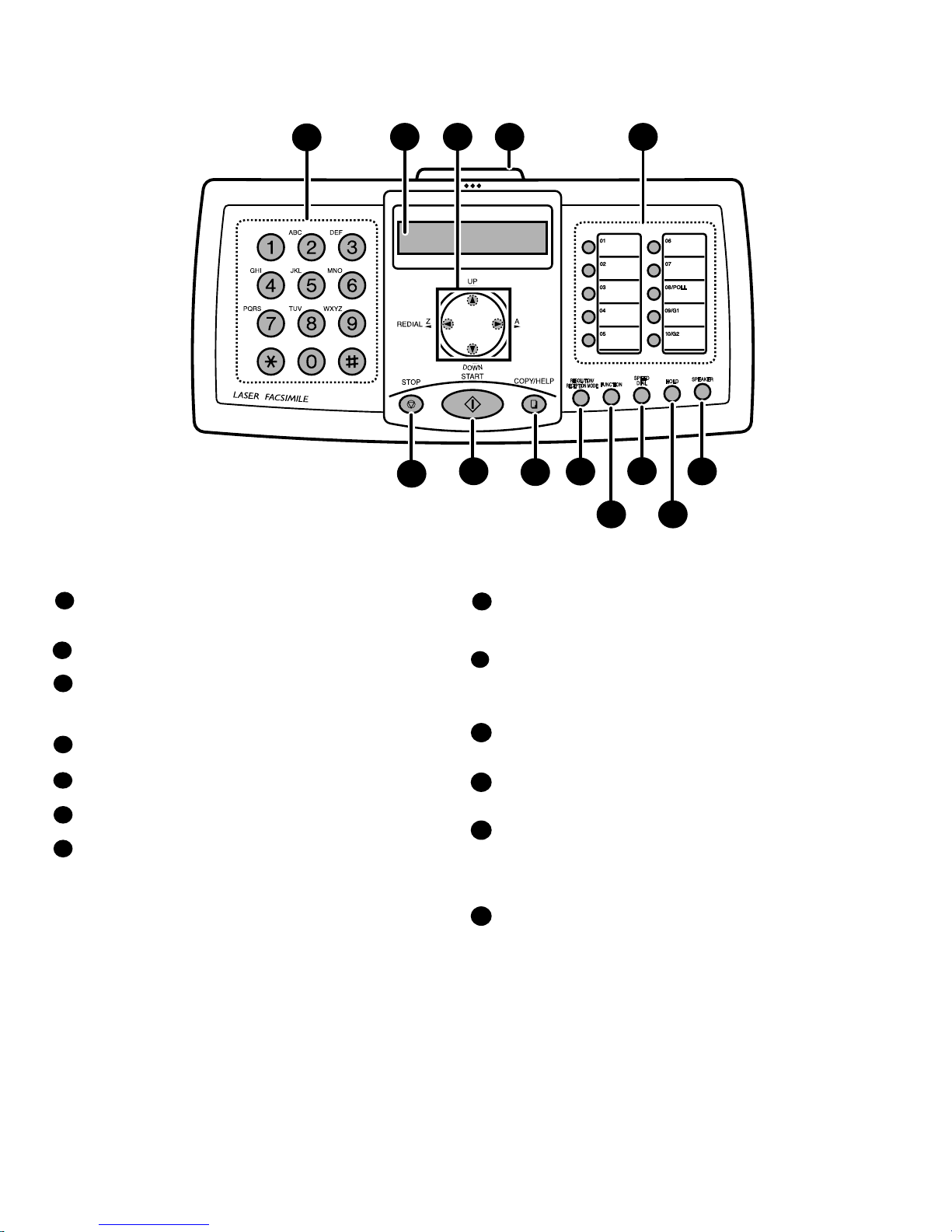
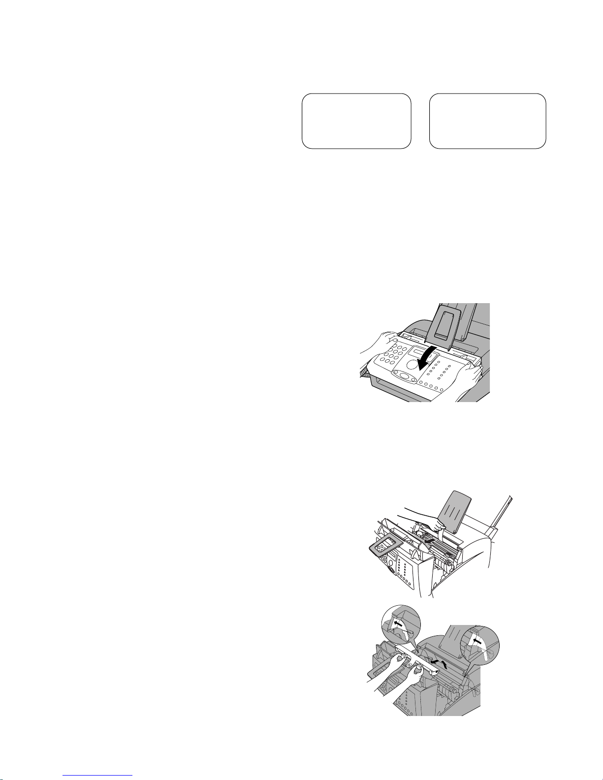
Toner cartridge yield**
(continuous printing,
4% page coverage,
letter paper)
Initial starter cartridge (included with fax machine):
Approx. 1,800 pages
Replacement cartridge FO-29ND: Approx. 3,700
pages
Drum cartridge yield**
(continuous printing,
4% page coverage,
letter paper)
Initial starter cartridge (included with fax machine):
Approx. 20,000 pages
Replacement cartridge (FO-29DR): Approx. 20,000
pages
Scanning Resolution Horizontal: 203 lines/inch (8 lines/mm)
Vertical:
Standard: 98 lines/inch (3.85 lines/mm)
Fine /Halftone: 196 lines/inch (7.7 lines/mm)
Super fine: 391 lines/inch (15.4 lines/mm)
Automatic document
feeder Letter/A4: 20 pages max. (20-lb. paper)
Legal: 5 pages max.
Recording system Laser
Compatibility ITU-T (CCITT) G3 mode
Paper tray capacity Letter: Approx. 200 sheets of 20-lb.
(70 g/m
2
)
copier paper, or 180 sheets of 21.5-lb.
(80 g/m
2
)
copier paper (at room temperature; maximum
stack height should not be higher than the line on
the tray)
Legal: 100 sheets
Recommended paper weight: 20-lb. Copy Bond
Halftone (grayscale) 64 levels
Compression scheme MR, MH, MMR
As a part of our policy of continuous improvement, SHARP reserves the right to make design and specification changes for product
improvement without prior notice. The performance specification figures indicated are nominal values of production units. There may be some
deviation from these values in individual units.
Dimensions (without
attachments) Width: 14.6" (372 mm)
Depth: 10.2" (259 mm)
Height: 8.0" (203 mm)
Weight (without
attachments) Approx. 11 lbs. (5.0 kg)
Important:
• This fax machine is not designed for use on a line which has call
waiting, call forwarding, or certain other special services offered by
your telephone company. If you attempt to use the fax machine in
conjunction with any of these services, you may experience errors
during transmission and reception of facsimile messages.
• This fax machine is not compatible with digital telephone systems.
Input document size Automatic feeding:
Width: 5.8 to 8.5" (148 to 216 mm)
Length (20 pages): 5.5 to 11.7" (140 to 297 mm)
Length (5 pages): 5.5 to 14" (140 to 356 mm)
Manual feeding:
Width: 5.8 to 8.5" (148 to 216 mm)
Length: 5.5 to 23.6" (140 to 600 mm)
Effective scanning width 8.3" (210 mm) max.
Effective printing width 8.2" (208 mm) max.
Contrast control Automatic/Dark selectable
Reception modes TEL/FAX/AM
Copy function Single/Multi/Sort (50 copies/page)
Telephone function Yes (cannot be used if power fails)
Applicable telephone line Public switched telephone network
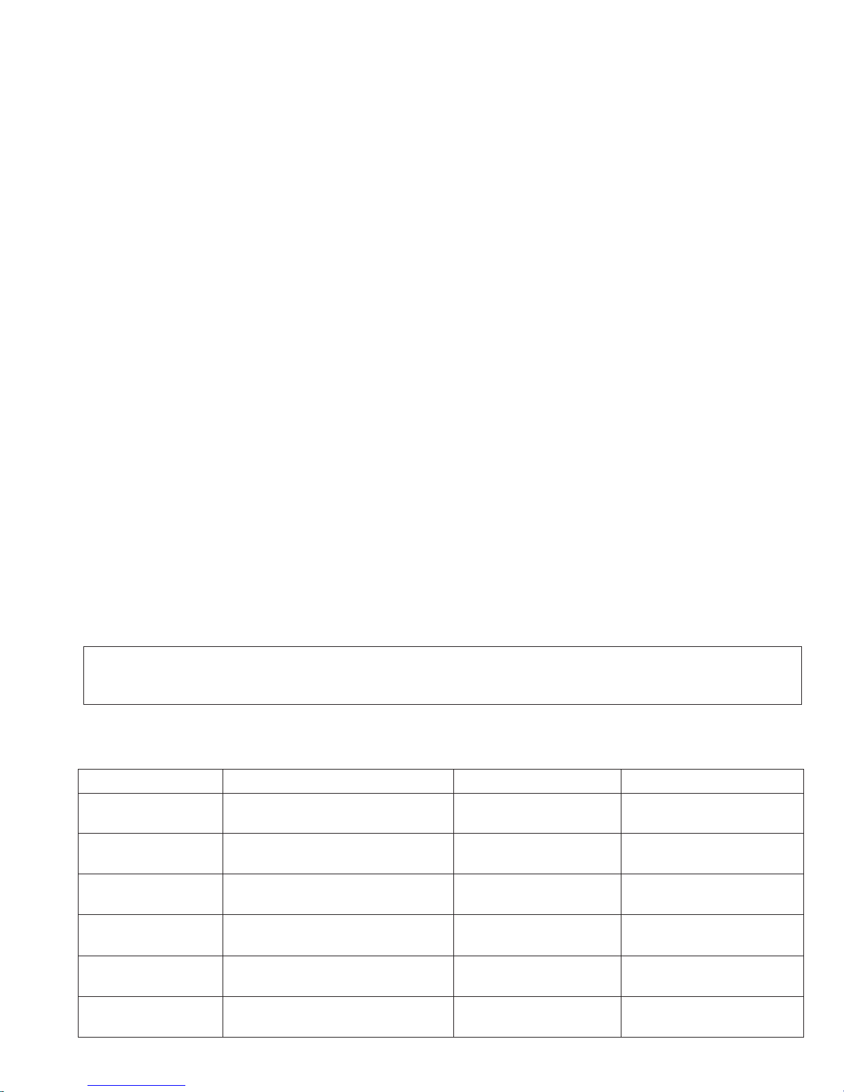
Display 16-digit LCD display
Power requirements 120 V AC, 60 Hz
Operating temperature 50 - 86 F (10 - 30°° C)
Humidity 20 - 85% RH
Power consumption Standby: 6.0 W
Maximum: 650 W
2 Life of consumable
Toner cartridge Replacement cartridge 3,700 prints User
(FO-29ND) (at Letter/4% chart)
Drum cartridge Replacement cartridge 20,000 prints User
(FO-29DR) (at Letter/4% chart)
Paper feed Transfer roller
(Refer to the P/G No. 8-25)
5 years Service Engineer
(NROLP7046XCZZ)
Fuser Fusing unit
(Refer to the P/G No. 9-901)
5 years Service Engineer
(DUNTW495CSC01)
Paper transport
Feed roller (Refer to the P/G No. 1-30)
Cleaning as needed ———————
(NROLR2333XHZZ)
Unit FO-3150 5 years or 30,000 prints ———————
of early either
Section Part Estimated Life Replaced by

1 – 2
FO-3150U/C
[2] Operation panel
Number keys
Use these keys to dial numbers, and enter numbers and letters when storing
auto-dial numbers.
Display
This displays messages and prompts to help you operate the machine.
Arrow keys
Use these keys to scroll through and select settings, and to search for auto-
dial numbers. Press the left arrow key (REDIAL) to select the last number
dialed.
PANEL RELEASE
Pull this release to open the operation panel.
Rapid Dial Keys
Press one of these keys to dial a fax number automatically.
STOP key
Press this key to cancel an operation before it is completed.
START key
Press this key after dialing to begin fax transmission. The key can also be
pressed in the date and time display to show the percentage of memory
currently used.
1
2
3
44
5
6
7
TEL FAX
A.M.
8
69
12 5
4
7
3
10 12
11 13
COPY/HELP key
When a document is in the feeder, press this key to make a copy of a
document. At any other time, press this key to print out the Help List, a quick
reference guide to the operation of your fax machine.
RESOLUTION / RECEPTION MODE key
When a document is in the feeder, press this key to adjust the resolution for
faxing or copying. At any other time, press this key to select the reception
mode (an arrow in the display will point to the currently selected reception
mode).
FUNCTION key
Press this key followed by the arrow keys to select special functions and
settings.
SPEED DIAL key
Press this key to dial a fax or voice number using an abbreviated 2-digit
Speed Dial number.
HOLD key
Press this key to put the other party on hold during a phone conversation.
When this is done, they cannot hear you. You can put the handset back in the
cradle without breaking the connection. When you are ready to speak with the
other party again, pick up the handset. If you did not put the handset back in
the cradle, press the HOLD key again to resume conversation.
SPEAKER key
Press this key to listen to the line and fax tones through the speaker when
faxing a document.
Note: This is not a speakerphone. You must pick up the handset to talk with
the other part
y
.
11
10
9
8
12
13

1 – 3
FO-3150U/C
[3] Transmittable documents
1. Document Sizes
* With special sizes, only one sheet can be fed into the machine at a
time. Insert next page into feeder as current page is being scanned.
2. Paper Thickness & Weight
3. Document Types
• Normal paper
Documents handwritten in pencil (No. 2 lead or softer), fountain pen,
ball point pen, or felt-tipped pen can be transmitted.
Documents of normal contrast duplicated by a copying machine can
also be transmitted.
• Diazo copy (blueprint)
Diazo copy documents of a normal contrast may be transmitted.
• Carbon copy
A carbon copy may be transmitted if its contrast is normal.
Normal size width 148 – 216 mm
length 128 – 279 mm
4. Cautions on Transmitting Documents
• Documents written in yellow, greenish yellow, or light blue ink cannot
be transmitted.
• Ink, glue, and correcting fluid on documents must be dry before the
documents can be transmitted.
• All clips, staples and pins must be removed from documents before
transmission.
• Patched (taped) documents should be copied first on a copier and
then the copies used for transmission.
• All documents should be fanned before insertion into the feeder to
prevent possible double feeds.
5. Automatic Document Feeder Capacity
Number of pages that can be placed into the feeder at anytime is as
follows:
Letter size: max. 20 sheets
Legal size: max. 5 sheets
Special size: single sheet only (manual feed)
NOTES: •If you need to send or copy more 20 pages, place the ad-
ditional pages and carefully in the feeder just before the
last page is scanned. Do not try to force them in, as this
may cause double-feeding or jamming.
•If your document consists of several large or thick pages
which must be loaded one at a time, insert each page into
the feeder as the previous page is being scanned. Insert
gently to prevent doublefeeding.
6. Readable Width & Length
The readable width and length of a document are slightly smaller than
the actual document size.
Note that characters or graphics outside the effective document scan-
ning range will not be read.
•Readable width
210 mm max.
•Readable length
This is the length of the document sent minus 0.16” (4 mm) from the top
and bottom edges.
Readable width
0.12" (3 mm) 0.12" (3 mm)
0.16" (4 mm)
0.16"
(
4 mm
)
Readable length
(Min.) (Max.)
letter
(Max.)
128 mm
279 mm 1.0 m
148 mm 216 mm
[
Normal size
]
216 mm
[
Special size
]
Product specifications
Indication Lower Limit Upper Limit
Weight Metric system 52g/m280g/m2
indication indication
Thickness Metric system 0.06mm 0.1mm
indication indication
Document Document size Minimum (148mm × 128mm)
size Range A4 (210mm × 297mm)
Letter (216mm × 279mm)
Legal (216mm × 356mm)
Number of Document size
Minimum ~ Letter/A4 size 20sheets
ADF sheets
Weight Legal 1 sheet
More than 90 kg
Below 135kg 1 sheet
Paper Kind Paper of fine quality/bond paper/
quality Kent paper

1 – 4
FO-3150U/C
[4] Installation
1. Site selection
Take the following points into consideration when selecting a site forthis
model.
ENVIRONMENT
•The machine must be installed on a level surface.
•Keep the machine away from air conditioners, heaters, direct sun-
light, and dust.
•Provide easy access to the front, back, and sides of the machine. In
particular, keep the area in front of the machine clear, or the original
document may jam as it comes out after scanning.
•The temperature should be between 10°and 30°C (50°and 86°F).
•The humidity should be between 20% and 85% (without condensa-
tion).
ELECTRICITY
AC 120 V, 60 Hz, grounded (3-prong) AC outlet is required.
Caution!
•Connection to a power source other than that specified will cause
damage to the equipment and is not covered under the warranty.
•Ifyourareaexperiencesahighincidenceoflightningorpowersurges,
we recommend that you install a surge protector for the power and
telephonelines.Surgeprotectorscanbepurchasedat most telephone
specialty stores
TELEPHONE SOCKET
Astandard RJ11C telephone socket must be located near the machine.
This is the telephone socket commonly used in most homes and offices.
•Plugging the fax machine into a socket which is not an RJ11C socket
may result in damage to the machine or your telephone system. If
you do not know what kind of socket you have, or need to have one
installed, contact the telephone company.
If the machine is moved from a cold to a warm place...
If the machine is moved from a cold to a warm place, it is possible that
thereading glass may fogup, preventing proper scanningof documents
for transmission. To remove the fog, turn on the power and wait approxi-
mately 2 hours before using the machine.
The laser printer in your fax machine uses a toner cartridge and a
drum cartridge. The drum cartridge comes pre-installed, and the
toner cartridge must be installed.
• The drum cartridge can print approximately 20,000 letter-size
pages. When replacing the drum cartridge, use a Sharp
FO-29DR drum cartridge.
Follow the steps below to install the toner cartridge and prepare the
drum cartridge.
1 Grasp the print compartment cover at both sides as shown, and
pull up to open the cover.
•Caution! The fusing unit inside the print compartment becomes
very hot during operation. Do not touch the inside of the
compartment or the paper guide on the underside of the print
compartment cover.
2
The drum cartridge has been installed at the factory. Remove the
protective board from above the drum cartridge, and then grasp the
tabs on the drum cartridge handle with both hands and gently pull
the cartridge out of the machine. Remove the sheet of protective
paper from the cartridge and then insert it back into the machine.
• When removing the drum cartridge, be careful not the tear the
paper or leave any pieces of paper in the machine.
The starter toner cartridge
included with your fax can
print approximately 1,800
letter-size pages at 4%
page coverage.
When replacing the toner
cartridge, use a Sharp
FO-29ND toner cartridge can
print about 3,700 letter-size
pages at 4% coverage.
2. Installing the toner cartridge

1 – 5
FO-3150U/C
3 Remove the new toner cartridge from its packaging. Shake the
cartridge side to side four or five times to distribute the tone
r
evenly within the cartridge.
4 Hold the toner cartridge by the handle with the stamped markings
on the cartridge facing upwards, and insert the cartridge into the
print compartment.
5 Place your thumb on the center of the handle where it is marked
PUSH, and push the handle down and in so that the cartridge fits
into place.
6 Close the print compartment cover, pressing down firmly on each
side to make sure it is completely closed.
7
Reset the toner counter and the drum counter as explained below.
Each time you install a new toner cartridge, follow the steps below to
reset the toner counter to zero. (The machine uses the toner counter to
inform you when the toner cartridge needs to be replaced.)
Each time you install a new drum cartridge, follow the steps below to
reset the drum counter to zero.
Resetting the toner counter
Resetting the drum counter
Press once and four times.
Press once and twice.
Press once.
Press .
Press to exit.
FUNCTION
START
STOP
Display:
PRESS START KEY
PRINT SET-UP
CLR TONER CNT.
CLR DRUM COUNT
1
2
3
4
5
1
2
3
4
5
Press once and four times.
Press once and once.
Press once.
Press .
Press to exit.
FUNCTION
START
STOP
Display:
PRESS START KEY
PRINT SET-UP
CLR DRUM COUNT
RECEIVE RATIO

1 – 6
FO-3150U/C
3. Replacing the drum cartridge
To maintain excellent printing quality, we recommend that you
replace the drum cartridge after 20,000 pages have been printed.
Follow these steps to view the total number of pages printed:
When 20,000 pages have been printed, DRUM LIFE OVER will appear in
the display. Replace the drum cartridge with the following cartridge:
1 Grasp the print compartment cover at both sides as shown, and
pull up to open the cover.
•Caution! The fusing unit inside the print compartment is very hot
during operation. Do not touch the inside of the compartment or
the paper guide on the underside of the print compartment cover.
Press once and four times.
Press once and three times.
Press once. The count will appear in the display.
When you are finished, press to exit.
FUNCTION
STOP
Display:
PRINT SET-UP
LIFE COUNTER
Sharp FO-29DR drum cartridge
Viewing the total number of pages printed
Replacing the drum cartridge
1
2
3
4
2 Grasp the finger hold on the toner cartridge handle where it is
marked PUSH, and pull the handle out. Hold the handle and pull
the toner cartridge out of the compartment.
• Place the toner cartridge on a sheet of paper on a level surface.
3 Grasp the tabs on the drum cartridge handle with both hands and
gently pull the cartridge out of the machine.
4 Remove the new drum cartridge from its packaging and then
remove the sheet of protective paper from the drum cartridge.
5 Insert the drum cartridge into the print compartment, holding the
tabs on the drum cartridge handle with both hands.
6 Replace the toner cartridge and close the print compartment cov-
er. When finished, reset the drum cartridge counter.
• To insert the cartridge, align the guides on the cartridge with the
runners on the sides of the compartment.

1 – 7
FO-3150U/C
2 Connecting the power cord
Plug the power cord into a 120 V, 60 Hz, grounded AC (3-prong)
outlet.
• Do not plug the power cord into any other kind of outlet. This will
damage the machine and is not covered under the warranty.
Insert one end of the line cord into the socket on the side of the
machine marked TEL. LINE. Insert the other end into a wall
telephone socket.
3 Connecting the telephone line cord
1 Connecting the handset
Connect the handset as shown and place it on the handset rest.
• The ends of the handset cord are identical, so they will go into
either socket.
Use the handset to make ordinary phone calls, or to transmit and
receive faxes manually.
Make sure the handset
cord goes into the jack
marked with a handset
symbol on the side of
the machine!
The machine does not
have a power on/off
switch, so the power is
turned on and off by
simply plugging in or
unplugging the power
cord.
Make sure that the line
cord is inserted into
the TEL LINE jack. Do
not insert it into the
TEL. SET jack!
The fax machine is set for tone dialing. If you are on a pulse dial line,
you must set the fax machine for pulse dialing. Press the keys on the
operation panel as follows:
4 Attaching the paper trays
1) Attach the paper tray.
2) Attach the paper tray cover.
Comments:
• The fax machine is not designed for use on a line which has call
waiting, call forwarding, or certain other special services offered
by your telephone company. If you attempt to use the fax
machine in conjunction with any of these services, you may
experience errors during transmission and reception of facsimile
messages.
• The fax machine is not compatible with digital telephone systems.
• If your area experiences a high incidence of lighting or power
surges, we recommend that you install surge protectors for the
power and telephone lines. Surge protectors can be purchased
from your dealer or at most telephone specialty stores.
Setting the dial mode:
1
2
3
4
5
Press once and 3 times.
Press once and 6 times.
Press once.
Select the dial mode:
TONE: PULSE:
Press to exit.
FUNCTION
12
STOP
Display:
The display briefly shows
your selection, then:
OPTION SETTING
DIAL MODE
QUIET TIME
1=TONE, 2=PULSE
If you will be loading legal
paper, flip up the paper tray
extension and extend the cover
before attaching the cover
4. Connections

1 – 8
FO-3150U/C
5Extension phone (optional)
1) Remove the seal covering the TEL. SET socket.
2) Connect the extension phone line to the TEL. SET socket.
If desired, you can connect an extension phone to the TEL. SET
jack on the fax.
3) Attach the received document tray.
4) Attach the original document support.
Make sure that
the
flanges face up
5. Loading Printing Paper
1 Remove the paper tray cover.
2 If you are going to load legal size paper, flip up the paper tray
extension and extend the paper tray cover.
3 Fan the paper, and then tap the edge against a flat surface to
even the stack.
4 Pull the paper release lever toward you.
You can load up letter, A4 or legal paper in the paper tray.
• Up to 200 sheets of 20 lb. (70 g/m
2
) paper can be loaded.
• Up to 180 sheets of 21.5 lb. (80 g/m
2
) paper can be loaded.
Caution!
Do not use the blank side of paper that has already been printed on.
5 Insert the stack of paper firmly into the tray, print side up.
• Make sure that the stack is not higher than the marked line.
Loading too much paper may cause paper jams and misfeeds.
• If paper remains in the tray, take it out and combine it into a
single stack with the new paper before adding the new paper.
Important:
Be sure to load the paper so that printing takes place on the
print side of the paper. Printing on the reverse side may result in
poor print quality.

1 – 9
FO-3150U/C
6 Make sure the stack of paper is aligned against the right pape
r
guide, and then gently move the left paper guide to the 8 1/2 posi-
tion for letter or legal paper, or the A4 position for A4 paper.
7 Push the paper release lever back down.
• Note: If the paper does not feed correctly, remove the entir
e
stack from the tray and repeat the loading procedure from the
beginning.
8 Replace the paper tray cover.
•If you loaded other than letter size paper (or you changed th
e
paper size), change the paper size setting as explained on the
following page.
The fax has been set at the factory to scale received faxes to letter size
paper. If you loaded legal or A4 size paper, you must change the paper
size setting to LEGAL or A4.
Setting the paper size
1
2
3
4
5
Press once and four times.
Press once and once.
Press once.
Select the paper size:
LETTER:
LEGAL:
A4:
Press to return to the date and time display.
FUNCTION
1
2
3
STOP
The display briefly shows
your selection, then:
PAPER SIZE SET
COPY CUT-OFF
1:LETTER
Display:
PRINT SET-UP
6. Clearing a jammed document
1 Open the operation panel by grasping the panel release and pull-
ing up.
2 Remove the document.
If the original document doesn't feed properly during transmission o
r
copying, or DOCUMENT JAMMED appears in the display, first try
pressing the START key. If the document doesn't feed out, open the
operation panel and remove it.
Important:
Do not try to remove a document without opening the operation
panel. This may damage the feeder mechanism .
3 Close the operation panel, making sure it clicks into place.
7. Clearing jammed printing paper
1 If most of the jammed page is protruding from the back of the fax,
remove the paper tray cover, pull the paper release lever toward
you, and try pulling the page out.
2
If the jammed page comes out, take out the rest of the paper in
the tray, straighten the stack, put it back in the paper tray, and
push down the paper release lever. Replace the paper tray cover.
•If you are unable to clear the jam in this way, continue with the
following steps.

1 – 10
FO-3150U/C
6 Wrap the drum cartridge in a large sheet of paper as shown at
right so that the green drum section is shielded from light, and
place it gently on a level surface.
•Do not touch the green drum in the drum cartridge. This will
damage the drum surface.
•Do not expose the drum to direct light. This will damage the
drum.
3 Grasp the print compartment cover at both sides as shown, and
pull up to open the cover.
• Caution!
The fusing unit inside the print compartment becomes very hot
during operation. Be careful not to touch the inside of the
compartment.
4 Grasp the finger hold on the toner cartridge handle where it is
marked PUSH, and pull the handle out. Hold the handle and pull
the toner cartridge out of the compartment.
•Place the toner cartridge on a sheet of paper on a level surface.
5 Grasp the tabs on the drum cartridge handle with both hands and
gently pull the cartridge out of the machine.
8 Replace the drum cartridge, holding the tabs on the drum car-
tridge handle with both hands.
•To insert the cartridge, align the guides on the cartridge with the
runners on the sides of the compartment.
9 Replace the toner cartridge and close the print compartment
cover. (Refer to Installing the Toner Cartridge.)
7 Gently pull the jammed paper out of the machine.
•If needed, turn the wheel on the right side of the fusing unit to
eject the paper from the machine.
• Caution!
Do not use excessive force to pull the jammed paper out. If the
paper tears and a piece remains inside the machine, a service
call may be necessary to remove the remaining piece.
Wheel
Fusing unit

1 – 11
FO-3150U/C
[5] Maintenance
1. Scanning glass and rollers.
Clean the scanning glass and rollers frequently to ensure that you
r
transmitted images and copies are of the highest quality.
Open the operation panel (grasp the panel release and up), and
wipe the scanning glass, rollers and white backplate with a soft
cloth.
2. The housing.
Wipe the external parts and surface of the machine with a dry cloth.
• Caution!
Do not use benzene or thinner. These solvents may damage o
r
discolor the machine.
1 Squeeze the panel release and open the operation panel.
•Make sure that all dirt and stains (such as correcting fluid) are
removed, as dirt and stains will cause vertical lines on transmitted
images and copies.
•Make sure that all dirt and stains (such as correcting fluied) are
removed. Dirt and stains will cause vertical lines on transmitted
images and copies.
If the scanning glass is difficult to clean
If you find it difficult to remove dirt from the scanning glass, you
can try moistening the swab with isopropyl alcohol or denatured
alcohol. Take care that no alcohol gets on the rollers.
2 Wipe the scanning glass (under the white roller) and rollers with a
cotton swab.
3 Close the operation panel.
White
backplate
Scanning glass
Document rollers
2 Grasp the finger hold on the toner cartridge handle where it is
marked PUSH, and pull the handle out. Hold the handle and pull
the toner cartridge out of the compartment.
•Place the toner cartridge on a sheet of paper on a level surface.
3 Grasp the tabs on the drum cartridge handle with both hands and
gently pull the cartridge out of the machine.
4 Take a sheet of clean paper and roll it into a tube. Roll it tightly
so that the diameter of the holes at each end is less than the
thickness of your little finger.
3. Cleaning the drum cartridge.
If you find that characters or parts of an image are missing from you
r
printed pages, the drum in the drum cartridge may need cleaning.
Follow the steps below to clean the drum.
1 Grasp the print compartment cover at both sides as shown, and
pull up to open the cover.
• Caution!
The fusing unit inside the print compartment becomes very hot during
operation. Do not touch the inside of the compartment or the pape
r
guide on the underside of the print compartment cover.

1 – 12
FO-3150U/C
6 Replace the drum cartridge, holding the tabs on the drum car-
tridge handle with both hands.
•To insert the cartridge, align the guides on the cartridge with the
runners on the sides of the compartment.
7 Replace the toner cartridge and close the print compartment cov-
er. (Refer to Installing the Toner Cartridge.)
5 Gently wipe the surface of the drum with the rolled-up paper to
remove any particles of toner caked on the drum.
•Do not let the drum surface come into contact with anything other
than the rolled-up paper. Fingerprints, water, alcohol, and othe
r
solvents will damage the drum surface.
•Do not touch the drum surface with the edges of the rolled-up
paper.
< NO GOOD >

1 – 13
FO-3150U/C
[6] Troubleshooting
1. Message and Signals
2 Audible signals
PRINTER ERROR A printer error has occurred. Open the printer
compartment cover, make sure the toner cartridge is
installed correctly, and then close the cover.
READY TO SEND A document has been loaded and the fax machine is
waiting for you to begin faxing or copying.
RECALLING This appears if you attempt to send a fax by
automatic dialing and the line is busy or the receiving
fax machine does not answer. Your fax machine will
automatically reattempt the call.
TONER EMPTY/
REPLACE TONER/
CLR TONER COUNT
(alternating messages)
The toner cartridge must be replaced. Printing is not
possible until the toner cartridge is replaced.
TONER NEAR EMPTY The toner cartridge is almost out of toner
(approximately 100 pages can be printed).
TOTAL PAGE(S) 01 Number of pages transmitted, received, or copied.
Continuous tone 3 seconds Indicates the end of transmission,
reception, or copying.
Intermittent tone
(3 beeps) 5 seconds
(1 second on, 1
second off)
Indicates incomplete transmission,
reception, or copying.
Rapid intermittent
tone 35 seconds
(0.7 seconds on,
0.3 seconds off)
Indicates that the handset is off hook.
1 Display messages
ADD PAPER & /
PRESS START KEY
(alternating messages)
Check the printing paper. If the tray is empty, add
paper and then press the START key. If there is paper
in the tray, make sure it is inserted correctly (take out
the stack, align the edges evenly, and then reinsert it
in the tray) and then press the STAR
Clearing Paper Jams
Tkey.
COVER OPEN The print compartment cover is open. Close it.
DIAL WAITING Dialing is not possible because the fax machine is
sending or receiving a fax, the handset is being used,
or an extension phone is being used.
DOCUMENT JAMMED The original document is jammed. See the following
section, . Document jams will
occur if you load more than 20 pages at once or load
documents that are too thick.
The document may also jam if the receiving machine
doesn't respond properly when you attempt to send a
fax.
DRUM LIFE OVER This appears when the drum cartridge needs
replacement.
FAX RX IN MEMORY A fax has been received in memory because the
toner cartridge needs replacement, you have run out
of printing paper, or the paper is jammed. The fax will
print out automatically when the problem is fixed.
FUNCTION MODE The FUNCTION key has been pressed.
GROUP SPACE FULL This appears if you attempt to program a Group Key
when all Group Keys have already been
programmed.
HEATER HIGH/
HEATER LOW/
HEATER ERROR
If one of these messages appears, unplug the power
cord and then plug it back in. If the message still
appears, call for service.
HOLD The HOLD key has been pressed to put the other
party on hold during a phone conversation. Press the
HOLD again to take the other party off hold.
LINE ERROR Transmission or reception was not successful. Press
the STOP key to clear the message and then try
again.
LINE IS IN USE An extension phone connected to the fax is being
used. Do not lift the fax's handset or attempt
transmission at this time, as this will interrupt the
conversation on the extension phone.
MEMORY IS FULL If faxes have been received to memory because
printing is not possible (an additional message will
indicate the problem), resolve the problem so that
printing can continue.
MEMORY PRINTING The fax is preparing to or printing out a document
from memory.
NO # STORED This appears if you attempt to search for an auto-dial
number when none have been stored.
OFF HOOK This appears if you forgot to replace the handset after
using it to dial and send a fax. Replace the handset or
press the STOP key to clear the message.
ON HOOK DIAL The SPEAKER key has been pressed and the fax
machine is waiting for you to dial.
PAPER JAMMED The printing paper is jammed.
POLYGON ERROR If this message appears, unplug the power cord and
then plug it back in. If the message still appears, call
for service.

1 – 14
FO-3150U/C
[7] Quick reference guide
Sending Faxes
Place your document
(up to 20 pages) face
down in the document
feeder.
Normal Dialing
1.Lift the handset or press .
2.Dial the fax number.
3.Wait for the reception tone (if a person
answers, ask them to press their Start
key).
4. Press .
Rapid Key Dialing
Press the appropriate Rapid Key.
Transmission will begin automatically.
Speed Dialing
1.Press
.
2.Enter the 2-digit Speed Dial number.
3. Press
Search Dialing
1.Press or until the
desired destination appears in the
display.
2. Press .
Direct Keypad Dialing
1.Dial the fax number.
2.Press .
SPEAKER
START
SPEED
DIAL
START
A
REDIAL
Z
START
START
Receiving Faxes
Press until the arrow in the display
points to the desired reception mode.
FAX mode: The fax machine automatically
answers and receives faxes.
TEL mode: Answer all calls (even faxes) by
picking up the handset. To begin fax
reception, press .
AM mode: Select this mode when you want
to use an answering machine that is
connected to the fax.
Storing Auto Dial Numbers
1.Press once and once.
2.Enter a 2-digit Speed Dial number (01 to
99; 01 to 10 for Rapid Key Dialing).
3.Enter the fax number and press .
4.Enter a name by pressing number keys.
(To enter two letters in succession that
require the same key, press after
entering the first letter.)
5. Press and then .
RESOLUTION/
RECEPTION MODE
START
FUNCTION
START
START
STOP
FAX
TEL
FAX
TEL
FAX
A.M.
A.M.
A.M.
TEL
JAN-03 10:30
JAN-03 10:30
JAN-03 10:30
A =
B =
C =
D =
E =
F =
G =
H =
I =
J =
K =
L =
M =
N =
O =
P =
Q =
R =
S =
T =
U =
V =
W =
X =
Y =
Z =
SPACE =
RESOLUTION/
RECEPTION MODE

FO-3150U/C
2 – 1
CHAPTER 2. ADJUSTMENTS
[1] Adjustments
General
Sincethefollowingadjustments and settings are provided for this model,
make adjustments and/or setup as necessary.
1. Adjustments
Adjustments of output voltage (FACTORY ONLY)
1. Install the power supply unit in the machine.
2. Set the recording paper and document.
3. When the document is loaded, power is supplied to the output lines.
Confirm that outputs are within the limits below.
Output voltage settings
Fig. 1
Printer PWB
1
CNPWCNPW 12
1
12
Power
Supply
PWB
2. High voltage power adjustments
The high voltage power adjustments are composed of the MC output
voltage adjustment and the DC bias output voltage adjustment. Either
adjustment is performed with the diag function. (MAIN CHG ADJUST
MODE)
1MC output voltage adjustment
In the measurement circuit shown below, adjust VR1 to be –1050V ~
–1200V (aim at –1100V)
MC
Measure with the high
voltage tester
(effective value meter). DRUM
• Capacitor: 1000pF/3KV (VCKYQY3FB102K)
• Diode: SHV-03 (VHDSHV03///-1)
Fig.2
+
–
MC output
voltage check
Output Voltage limits
+5V 4.75V~5.25V
+24VH 23.04V~24.96V
+24V* 23.04V~24.96V
PIN No. Connector
No. CNPW
1 +5V
2DG
3DG
4 +24VH
5MG
6MG
7 +24VS
8 PWRLY–
9 HLON–
10 +24V
11 +24V
12 ZC

FO-3150U/C
2 – 2
2DC bias output voltage adjustment
Adjust VR2 so that the output voltage is –310V ±5V
For measurement, use the high voltage tester (effective value me-
ter).
VR1 (MC output voltage adjustment volume)
+
–
DC-Bias
Output voltage check
VR2
(DV bias output adjustment volume)
DC-Bias
Output voltage check
–
+
DRUM
DC-Bias
3Transfer charger voltage check
After MC output voltage adjustment and DC bias output voltage ad-
justment, check transfer charger voltage.
Check that the output voltage is +3200V ~ +3700V.
For measurement, use a high voltage tester (effective value meter).
Transfer charger
Output voltage check
+
–DRUM
D7
D8
Note: For measurement, do not remove Printer PWB from the bottom
plate.
VR1 (MC output voltage adjustment volume)
+
–
Transfer changer
Output voltage check
Fig.3
Fig.4

FO-3150U/C
2 – 3
3. IC protectors replacement
ICPs (IC Protectors) are installed to protect the TX motor drive circuit
and verification stamp drive circuit. ICPs protect various ICs and elec-
tronic circuits from an overcurrent condition.
The location of ICPs are shown below:
FU100
CNMT CNLIUA
CNSP
CNPRG
CNPRT
CNRTH
CNFUSE
CNFAN
CNPN
CNCIS
IC1
(step 1) Select "OPTION SETTING".
DISPLAY:
DISPLAY:
DISPLAY: TONE SELECTED
KEY:
FUNCTION
KEY:
KEY:
OPTION SETTING
KEY:
1= TONE, 2= PULSE
KEY:
KEY:
DISPLAY:
(step 4) End, using the "STOP" key.
(step 3) Select, using "1" or "2".
(step 2) Select "DIAL MODE".
Push until " DIAL MODE " is
indicated because the number of
s changes by the models and press key.
1
2
PULSE SELECTED
STOP
(1) FU100is installed in order to protectIC’sfrom and overcurrentgen-
erated in the verification stamp drive circuit. If FU100 is open, re-
place it with a new one.
4. Settings
(1) Dial mode selector
OPTION SETTING: DIAL MODE (Soft Switch No. SW2 DATA No. 1)
Use this to set the fax machine to the type of telephone line you are on.
• The factory setting is "TONE".
Control PWB (Bottom side)
Fig.5

FO-3150U/C
2 – 4
[2] Diagnostics and service soft switches
1. Operating procedure
Two kinds of diagnoses are supported.
1-1. Fax diagnosis
This diagnosis is concerned with the main body of fax which is used
for production and service support.
Entering the diagnostic mode
1-2. Print diagnosis
This diagnosis is concerned with the print which is used for
production and service support.
Entering the diagnostic mode
Memory clear when power is turned on
Pressingthe STOPkeys,turn on the main power,and the followingmes-
sage will be displayed.
Press START key, the memory will be cleared to be ready for operation.
Press COPY key, the memory will be cleared to be ready for process
check.
If press the other keys, it will continue ready for operation as it is.
Press , and the following
display will appear.
FUNC
9 8 6
PRINT DIAG MODE
(Diag•specifications)
FUNC
986
START01 AREA PRINT MODE
START02 CHECK PATTERN 1
START03 CHECK PATTERN 2
START
04 CHECK PATTERN 3
START
05 PAPER FEED AGING
START
07 LIFE SET MODE
START
06 PAPER FEED AGING 2
START
08 LIFE ALL CLEAR
START
START
09 LIFE ENTRY MODE
START
10 TOP ADJUST MODE
START
START
Then press the key. Select the desired item with the
key and the key or select with the rapidkey.
Enter the mode with the key.
START
11 LIFE CLEAR MODE
START
12 MAIN CHARGER ADJUST
PRINT DIAG MODE
MEMORY CLEAR?
FUNC 9 8 7
START01 SOFT SWITCH MODE
START
02
START03
ROM & RAM CHECK
START
04
AUTO FEEDER MODE
AGING MODE
START
06
PANEL KEY TEST
CHECK PATTERN MODE
START
07
START05
START08
START
09
SIGNAL SEND MODE
START
10
ENTRY DATA SEND MODE
MEMORY CLEAR MODE
ENTRY DATA RECEIVE MODE
START
FUNC
9 8 7
Press
FO-3150U:
FO-3150C:
, and the following
display will appear.
DIAG
TB26
FO-3150U:
FAX ROM
Version Printer
ROM version
MODE
START
Then press the key. Select the desired item with the key
and the key or select with the rapid key.
Enter the mode with the
START
key.
(Diag
•
specifications)
/PL2
TC03 /PL2
TB26 /PL2
FO-3150C:
TC03 /PL2
Other manuals for FO-3150
4
This manual suits for next models
1
Table of contents
Other Sharp Fax Machine manuals

Sharp
Sharp UX-P115 User manual

Sharp
Sharp FO-1460 User manual

Sharp
Sharp FO-2200 User manual

Sharp
Sharp UX-D50 User manual

Sharp
Sharp UX-340L User manual

Sharp
Sharp FO-1450 User manual

Sharp
Sharp FO-4650 User manual

Sharp
Sharp UX-A1000 User manual

Sharp
Sharp FO-5500 User manual

Sharp
Sharp FO-B1600 User manual