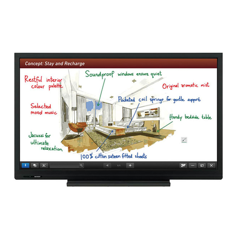
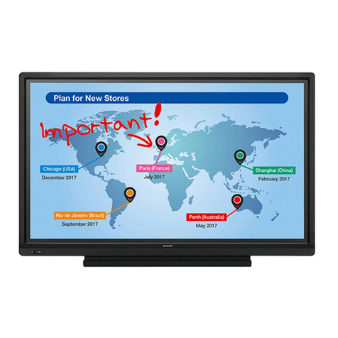
Sharp PN-T322B User manual

CODE : 00Z
SERVICE MANUAL
CONTENTS
Parts marked with "!" are important for maintaining the safety of the set. Be sure to replace these parts with specified
ones for maintaining the safety and performance of the set.
This document has been published to be used
for after sales service only.
The contents are subject to change without notice.
PNT321SME2
LCD MONITOR/
TOUCH-PANEL-
INTEGRATED DISPLAY
PN-T321
MODEL PN-T322B
■LEAD-FREE SOLDER
CHAPTER 1. OUTLINE OF THE PRODUCT . . . . . . . . . . . . . . . . . 1 - 1
CHAPTER 2. INSTALLATION, ADJUSTMENT, SETTING. . . . . . . 2 - 1
CHAPTER 3. CONTROLLING THE MONITOR WITH A PC . . . . . 3 - 1
CHAPTER 4. IMPORTANT INFORMATION FOR SERVICING
THE DISPLAY . . . . . . . . . . . . . . . . . . . . . . . . . . . . . 4 - 1
CHAPTER 5. SERVICE MENU/VARIOUS SETTING TOOL
OPERATING PROCEDURES . . . . . . . . . . . . . . . . . 5 - 1
CHAPTER 6. FIRMWARE UPDATA PROCEDURES/EDID
WRITING PROCEDURES . . . . . . . . . . . . . . . . . . . . 6 - 1
CHAPTER 7. DISASSEMBLY AND ASSEMBLY . . . . . . . . . . . . . . 7 - 1
CHAPTER 8. TROUBLESHOOTING . . . . . . . . . . . . . . . . . . . . . . . 8 - 1
CHAPTER 9. HARDWARE DESCRIPTIONS. . . . . . . . . . . . . . . . . 9 - 1

i
CONTENTS
CHAPTER 1.
OUTLINE OF THE PRODUCT
1 SPECIFICATIONS 1 - 1
2 PART NAMES AND FUNCTION 1 - 6
3 SCREEN DISPLAY 1 - 11
CHAPTER 2.
INSTALLATION, ADJUSTMENT, SETTING
1 INSTALLATION 2 - 1
2 ADJUSTMENT 2 - 5
3
SETTING UP THE PC (TOUCH PANEL DRIVER)
2 - 10
CHAPTER 3.
CONTROLLING THE MONITOR WITH A PC
1 RS-232C 3 - 1
CHAPTER 4.
IMPORTANT INFORMATION FOR SERVICING
THE DISPLAY
1 I/F PWB, LCD MODULE, PARTS REPLACEMENT
PROCEDURES 4 - 1
CHAPTER 5.
SERVICE MENU/VARIOUS SETTING TOOL
OPERATING PROCEDURES
1 OPERATING PRCEDURES 5 - 1
2AGING 5-2
3 FACTORY RESET 5 - 2
4 EDID WRITE PROTECT 5 - 2
5 NTSC SETUP LEVEL 5 - 3
6 INSTRUCTIONS FOR LAUNCHER TOOL 5 - 3
7 SERIAL NUMBER WRITING PROCEDURES 5 - 4
8 USAGE TIME SETTING PROCEDURE 5 - 5
9 TEMPERATURE MONITOR SETTING PROCE-
DURES 5 - 6
10 PERATING PROCEDURES Of TOUCH PANEL
INSPECTION TOOL 5 - 8
CHAPTER 6.
FIRMWARE UPDATA PROCEDURES/EDID WRIT-
ING PROCEDURES
1 MAIN FIRMWARE UPDATE PROCEDURE 6 - 1
2 EDID WRITING PROCEDURES 6 - 2
CHAPTER 7.
DISASSEMBLY AND ASSEMBLY
1 PWB AND WIRING DIAGRAM 7 - 1
2 REAR COVER 7 - 3
3 SPEAKER UNIT 7 - 4
4 LED DRIVER PWB 7 - 5
5 INLET HARNESS/AC SWITCH 7 - 6
6 POWER SUPPLY PWB 7 - 8
7 TEMPERATURE SENSOR PWB 7 - 8
8 I/F PWB 7 - 9
9 LCD MODULE 7 - 13
10 KEY PWB 7 - 15
11 TOUCH PANEL ASSEMBLY (PN-T322B) 7 - 16
CHAPTER 8.
TROUBLESHOOTING
1 THE POWER IS NOT TURNED ON
(THE LED DOES NOT LIGHT UP) 8 - 1
2
THE REMOTE CONTROLLER DOES NOT WORK
8 - 2
3 THE DISPLAY DOES NOT APPEAR
(DISPLAY ABNORMALITY) 8 - 2
4 THE BACKLIGHT DOES NOT LIGHT UP 8 - 3
5 NO SOUND IS GENERATED/ REPRODUCED
SOUND ABNORMALITY 8 - 3
6 RS-232C CONTROL DOES NOT WORK 8 - 3
7 NO RESPONSE FOR TOUCHING 8 - 4
8 THE TOUCH POSITION IS SHIFTED 8 - 5
9 THE TOUCH POSITION IS SHIFTED EVEN
AFTER CALIBRATION 8 - 5
10 MULTI-TOUCH IS UNABLE 8 - 6

ii
CHAPTER 9.
HARDWARE DESCRIPTIONS
1 SYSTEM DESCRIPTION 9 - 1
2 FUNCTIONS 9 - 3
3 PERFORMANCE SPECIFICATIONS 9 - 3
4 BLOCK DIAGRAM 9 - 4
5 TOUCH PANEL (PN-T322B) 9 - 5

ii
The PWB’ s of this model employs lead-free solder. The “LF” marks indicated on the PWB’s and the Service Manual mean
“Lead-Free” solder. Thealphabet following the LF mark shows the kind of lead-free solder.
If the soldering iron tip is discolored black during soldering work, cleanand file the tip with steel wool or a fine filer.
If different-kind solder remains on the soldering iron tip, it is melted together with lead-free solder. To avoid this, clean the soldering iron
tip after com-pletion of soldering work.
Since lead-free solder includes a greater quantity of tin, the iron tip may corrode easily. Turn ON/OFF the soldering iron power frequently.
Since the melting point of lead-free solder is about 220˚C, which is about 40˚C higher than that of conventional lead solder, and its
soldering capacityis inferior to conventional one, it is apt to keep the soldering iron in contact with the PWB for longer time. This may
cause land separation or mayexceed the heat-resistive temperature of components. Use enough care to separate the soldering iron
from the PWB when completion of soldering isconfirmed.
(2) NOTE FOR SOLDERING WORK
(1) NOTE FOR THE USE OF LEAD-FREE SOLDER THREAD
Since the melting point of lead-free solder thread is about 40˚C higher than that of conventional lead solder thread, the use of the
exclusive-use solder-ing iron is recommendable.
When repairing a lead-free solder PWB, use lead-free solder thread. Never use conventional lead solder thread, which may cause a
breakdown or anaccident.
Example:
LEAD-FREE SOLDER
The battery supplied with this product contains traces of Lead.
For EU:
For Switzerland:
The used battery is to be returned to the selling point.
For other non-EU countries:
Please contact your local authority for correct method of disposal of the used battery.
“BATTERY DISPOSAL”
U.S.A.ANDCANADAONLY
The crossed-out wheeled bin implies that used batteries should not be put to the general householdwaste!
There is a separate collection system for used batteries, to allow proper treatment and recycling in accordance with
legislation. Please contact your local authority for details on the collection and recycling schemes.
THIS PRODUCT CONTAINS A LITHIUM PRIMARY (MANGANESS DIOXIDE) MEMORY BACK-UP BATTERY THAT MUST BE
DISPOSED OF PROPERLY. PLEASE CONTACT YOUR LOCAL SHARP DEALER OR AUTHORIZED SERVICE REPRESENTATIVE
FOR ASSISTANCE IN DISPOSING OF THIS BATTERY.
<Solder composition code of lead-free solder>
Bi-Sn-Ag
b
p
Solder composition Solder composition code
a
Sn-Ag-Cu
Sn-Ag-Bi
Sn-Ag-Bi-Cu
z
Sn-Zn-Bi
i
Sn-In-Ag-Bi
n
Sn-Cu-Ni
s
Sn-Ag-Sb
Bi-Sn-Ag-P
Lead-Free
Solder composition
code (Refer to the
table at the right.)
a
5mm
“
CAUTION
”
RISK OF EXPLOSION IF BATTERY IS REPLACED BY AN INCORRECT TYPE.
DISPOSE OF USED BATTERIES ACCORDING TO THE INSTRUCTIONS
CAUTION
DOUBLE POLE/NEUTRAL FUSING

PN-T321/T322B OUTLINE OF THE PRODUCT
1 – 1
CHAPTER 1. OUTLINE OF THE PRODUCT
1. SPECIFICATIONS
1 - 1. OUTLINE
Model PN-T321 PN-T322B
LCD component 32" Class [31-1/2 inch (80 cm) diagonal] TFT LCD
Max. resolution (pixels) 1366 x 768
Max. colors Approx. 16.77 million colors
Pixel pitch 0.511mm (H) x 0.511mm (V)
Viewing angle 176° right/left/up/down (contrast ratio>10)
Screen active area inch (mm) 27-7/16 x 15-7/16 (697.7 x 392.3)
Computer input signal
nDigital (DVI 1.0 standard-compliant)
nAnalog RGB (0.7 Vp-p) [75Ω]
Sync signal
nHorizontal/vertical separate (TTL: positive/negative)
nSync-on-green
nComposite sync (TTL: positive/negative)
Video color system
nNTSC (3.58MHz)
nNTSC (4.43MHz)
nPAL
nPAL-60
nSECAM
Plug and play VESA DDC2B
Power management
nVESA DPMS
nDVI DMPM
Input terminals
Digital HDMI x 1
DVI-D 24 pin (HDCP compatible) x 1
Analog Mini D-SUB 15 pin, 3 rows x 1
Composite video RCA pin x 1 *1
Component RCA pin (Y, Cb/Pb, Cr/Pr) x 1 *2
Audio 3.5mm mini stereo jack x 1
RCA pin (L/R) x 1 *1
Serial (RS-232C) D-SUB 9 pin x 1
USB flash drive x 1 (for slideshow)
Output terminal Audio 3.5mm mini stereo jack x 1
Speaker output 8 W + 8 W
Touch Panel
Detection method --- Infrared camera method
Detection area inch (mm) --- 27 x 15 (685.7 x 380.3)
PC connector --- USB (1.1 compliant)
Power supply --- Supplied from USB
Position accuracy inch (mm) --- ±1/4 (±6)
Power requirement AC 100 V - 240 V, 50/60 Hz
Operating temperature *332° F to 104° F (0°C to 40°C) 41° F to 95° F (5°C to 35°C)
Operating humidity 20% to 80% (no condensation)
Power consumption
(input signal waiting mode / standby mode)
82 W
(0.9 W *4/0.9 W)
Dimensions (excluding protrusions) inch (mm) Approx. 30-1/4 (W) x 1-15/16 (D) x
18-1/8 (H) (769 x 49.1 x 461)
Approx. 30-1/4 (W) x 2-7/16 (D) x
18-1/8 (H) (769 x 62 x 461)
Weight lbs. (kg) Approx. 17.2 (7.8) Approx. 24.3 (11)

CHAPTER 1. OUTLINE OF THE PRODUCT
PN-T321/T322B OUTLINE OF THE PRODUCT
1 – 2
*1 Uses the provided conversion cable (for AV video).
*2 Uses the provided conversion cable (for AV component).
*3 Temperature condition may change when using the display together with the optional equipments recommended by SHARP.
In such cases, please check the temperature condition specified by the optional equipments.
*4 D-SUB input (factory default setting)
As a part of our policy of continuous improvement, SHARP reserves the right to make design and specification changes for product improvement
without prior notice. The performance specification figures indicated are nominal values of production units. There may be some deviations from
these values in individual units.
1 - 2. DIMENSIONAL DRAWINGS
*Note that the values shown are approximate values.
*1 When mounting the monitor, be sure to use a wall-mount bracket that complies with the VESA-compatible mounting method.
SHARP recommends using M6 screws and tighten the screws.
Note that screw hole depth of the monitor is 3/8 inch (10mm). Loose mounting may cause the product to fall, resulting in serious personal inju-
ries as well as damage to the product. The screw and hole should come together with over 5/16 inch (8mm) length of thread. Use a bracket
which has been approved for UL1678 standard, and which can endure at least 4 times or more the weight of the monitor.
18-13/16 [478]
30-1/4 [769]7-7/8 [200]
7-7/8 [200]
Unit: inch [mm]
VESA holes *1
Opening width (27-5/8 [701])
18-1/8 [461]
Opening height
(15-9/16 [396])
1-1/2
[38]
2-7/16
[62]
1-15/16
[49.1]
1
[25.3]
PN-T322B PN-T321

CHAPTER 1. OUTLINE OF THE PRODUCT
PN-T321/T322B OUTLINE OF THE PRODUCT
1 – 3
1 - 3. COMPATIBLE SIGNAL TIMING (PC)
*1 Displays a reduced image, except in Dot by Dot. In Dot by Dot, the image will be cut down to panel size then displayed.
*2 Displays as an AV signal (1280 x 720p).
*3 Displays as an AV signal (1920 x 1080p).
*All are compliant only with non-interlaced.
*Depending on the connected PC, images may not be displayed properly even if the compatible signal described above is input.
*The frequency values for the Sun are reference values.
Screen resolution Hsync Vsync Dot frequency Digital Analog
DVI-D HDMI
VESA 640 x 480 31.5kHz 60Hz 25.175MHz Yes Yes Yes
37.9kHz 72Hz 31.5MHz Yes Yes Yes
37.5kHz 75Hz 31.5MHz Yes Yes Yes
800 x 600 35.1kHz 56Hz 36.0MHz --- --- Yes
37.9kHz 60Hz 40.0MHz Yes Yes Yes
48.1kHz 72Hz 50.0MHz Yes Yes Yes
46.9kHz 75Hz 49.5MHz Yes Yes Yes
848 x 480 31.0kHz 60Hz 33.75MHz Yes --- Yes
1024 x 768 48.4kHz 60Hz 65.0MHz Yes Yes Yes
56.5kHz 70Hz 75.0MHz Yes Yes Yes
60.0kHz 75Hz 78.75MHz Yes Yes Yes
1152 x 864 *167.5kHz 75Hz 108.0MHz Yes Yes Yes
1280 x 768 47.8kHz 60Hz 79.5MHz Yes --- Yes
60.3kHz 75Hz 102.25MHz Yes --- Yes
1280 x 800 *149.7kHz 60Hz 83.5MHz Yes Yes Yes
1280 x 960 *160.0kHz 60Hz 108.0MHz Yes Yes Yes
1280 x 1024 *164.0kHz 60Hz 108.0MHz Yes Yes Yes
80.0kHz 75Hz 135.0MHz Yes Yes Yes
1360 x 768 47.7kHz 60Hz 85.5MHz Yes Yes Yes
1400 x 1050 *165.3kHz 60Hz 121.75MHz Yes Yes Yes
1440 x 900 *155.9kHz 60Hz 106.5MHz Yes --- Yes
1600 x 1200 *175.0kHz 60Hz 162.0MHz Yes Yes Yes
1680 x 1050 *165.3kHz 60Hz 146.25MHz Yes Yes Yes
Wide 1280 x 720 44.7kHz 60Hz 74.4MHz Yes *2Ye s *2Ye s
1366 x 768 47.7kHz 60Hz 85.383MHz Yes Yes Yes
1920 x 1080 *166.3kHz 60Hz 148.5MHz Yes Yes Yes
67.5kHz 60Hz 148.5MHz Yes *3Ye s *3Ye s
US TEXT 720 x 400 31.5kHz 70Hz 28.3MHz Yes Yes Yes
Sun 1024 x 768 48.3kHz 60Hz 64.13MHz --- --- Yes
53.6kHz 66Hz 70.4MHz --- --- Yes
56.6kHz 70Hz 74.25MHz --- --- Yes
1152 x 900 *161.8kHz 66Hz 94.88MHz --- --- Yes
71.8kHz 76.2Hz 108.23MHz --- --- Yes
1280 x 1024 *171.7kHz 67.2Hz 117.01MHz --- --- Yes
81.1kHz 76Hz 134.99MHz --- --- Yes
1600 x 1000 *168.6kHz 66Hz 135.76MHz --- --- Yes
CHAPTER 1. OUTLINE OF THE PRODUCT
PN-T321/T322B OUTLINE OF THE PRODUCT
1 – 4
1 - 4. COMPATIBLE SIGNAL TIMING (AV)
*1 Displays a reduced image, except in Dot by Dot. In Dot by Dot, the image will be cut down to panel size then displayed.
1 - 5. POWER MANAGEMENT
This monitor conforms to VESA DPMS and DVI DMPM. Both your video
card and computer must support the same standard in order for the
monitor’s power management function to work.
DPMS: DISPLAY POWER MANAGEMENT SIGNALING
DMPM: DIGITAL MONITOR POWER MANAGEMENT
1 - 6. DDC (PLUG AND PLAY)
The monitor supports the VESA DDC (Display Data Channel) standard.
DDC is a signal standard for plug and play between monitors and com-
puters. Information about resolution and other parameters is exchanged
between the two. This function can be used if the computer supports
DDC and it has been configured to detect plug-and-play monitors.
There are several types of DDC, depending on the communication
method used. This monitor supports DDC2B.
1 - 7. SUPPLIED ACCESSORIES
nLiquid Crystal Display Monitor: 1
nRemote control unit: 1 (Battery preinstalled)
nCable clamp: 1
nPower cord: 1
nConversion cable (for AV component): 1 (green/ blue/ red)
nConversion cable (for AV video): 1 (red/ white/ yellow)
nCD-ROM (Utility Disk for Windows): 1
*Sharp Corporation holds authorship rights to the Utility Disk pro-
gram. Do not reproduce it without permission.
nSetup Manual: 1
nVertical sticker (Operation panel): 1
nVertical sticker (Logo): 1
nUSB flash drive cover: 1
nUSB flash drive cover screw (+): 1 (PN-T321)
nUSB flash drive cover screw (-): 1 (PN-T322B)
nCover Sharp logo: 1
Place this sticker onto the SHARP logo to cover the logo.
nAir blower: 1 (PN-T322B)
*For environmental protection!
Do not dispose of batteries in household waste.
Follow the disposal instructions for your area.
Screen resolution Frequency DVI-D HDMI Component
1920 x 1080p *124Hz --- Yes ---
50Hz Yes Yes Yes
59.94Hz Yes Yes Yes
60Hz Yes Yes Yes
1920 x 1080i *150Hz Yes Yes Yes
59.94Hz Yes Yes Yes
60Hz Yes Yes Yes
1280 x 720p 50Hz Yes Yes Yes
59.94Hz Yes Yes Yes
60Hz Yes Yes Yes
720 x 576p 50Hz Yes Yes Yes
720 x 480p 59.94Hz Yes Yes Yes
60Hz Yes Yes Yes
720 (1440) x 576 50Hz --- Yes Yes
720 (1440) x 480i 59.94Hz --- Yes Yes
60Hz --- Yes Yes
DPMS Screen Power
consumption Hsync Vsync
ON STATE Display 82W Yes Yes
STANDBY No
display
0.9W No Yes
SUSPEND Yes No
OFF STATE No No
DMPM Screen Power
consumption
Monitor ON Display 82W
Active OFF No display 10W

CHAPTER 1. OUTLINE OF THE PRODUCT
PN-T321/T322B OUTLINE OF THE PRODUCT
1 – 5
1 - 8. LAYOUT OF TERMINAL PINS
■PC/AV DVI-D INPUT TERMINAL PINS
■RS-232C INPUT TERMINAL PINS
■PC D-SUB INPUT TERMINAL PINS
■PC/AV HDMI INPUT TERMINAL PINS
No. Function No. Function
1 TMDS data 2- 13 N.C.
2 TMDS data 2+ 14 +5V
3 TMDS data 2/4 shield 15 GND
4 N.C. 16 Hot-plug detection
5 N.C. 17 TMDS data 0-
6 DDC clock 18 TMDS data 0+
7 DDC data 19 TMDS data 0/5 shield
8 N.C. 20 N.C.
9 TMDS data 1- 21 N.C.
10 TMDS data 1+ 22 TMDS clock shield
11 TMDS data 1/3 shield 23 TMDS clock+
12 N.C. 24 TMDS clock-
No. Function No. Function
1N.C. 6N.C.
2 Transmitted data 7 N.C.
3 Received data 8 N.C.
4N.C. 9N.C.
5GND
(DVI-D 24 PIN)
(D-SUB 9 PIN)
No. Function No. Function
1 Red video signal input 9 +5V
2 Green video signal input 10 GND
3 Blue video signal input 11 N.C.
4 N.C. 12 DDC data
5 GND 13 Hsync signal input
6 GND for red video signal 14 Vsync signal input
7 GND for green video signal 15 DDC clock
8 GND for blue video signal
No. Function No. Function
1 TMDS data 2+ 11 TMDS clock shield
2 TMDS data 2 shield 12 TMDS clock-
3 TMDS data 2- 13 N.C.
4 TMDS data 1+ 14 N.C.
5 TMDS data 1 shield 15 SCL
6 TMDS data 1- 16 SDA
7 TMDS data 0+ 17 DDC/CEC GND
8 TMDS data 0 shield 18 +5V
9 TMDS data 0- 19 Hot-plug detection
10 TMDS clock+
(Mini D-SUB 15 PIN)
(HDMI CONNECTOR)
TM

CHAPTER 1. OUTLINE OF THE PRODUCT
PN-T321/T322B OUTLINE OF THE PRODUCT
1 – 6
2. PART NAMES AND FUNCTION
2 - 1. DISPLAY
■FRONT VIEW
MEMO
nUse a pointed object such as a pen tip to press the switches at
the operation panel.
REFERENCE CHART OF POWER LAMP LIGHTING STATUS
23 45
1
1LCD panel
2Power LED
3Power switch
4Input switch
5Remote control sensor
Lighting Status Status Description
Green lamp is lit. In the power “ON” state
Green lamp is flashing. In the input signal waiting mode (When DVI-D or D-SUB)
Orange lamp is lit. In the power “OFF” state (Standby status=The power is turned off by the remote controller.)
If the Power switch is pressed when the display is in the input signal waiting mode (green lamp flashing), it also goes
into the standby status.
Lamp is flashing in
red3green3red3green
at 1 second intervals.
(Temperature
abnomaly)
The message “TEMPERATURE” blinks at 5-second intervals in the corner of the screen (Lower left corner at the fac-
tory default), and it indicates an abnormality in the internal temperature.
*It operates only when “FUNCTION” - “TEMPERATURE ALERT” is set to “OSD&LED” or “LED”.
When it is “OFF”, it does not blink. (Factory default: “LED”)
*Even when “FUNCTION” - “LED” is set to “OFF”, the setting of “TEMPERATURE ALERT” takes effect.
At the same time, the brightness is forcefully reduced by the internal processing of the LCD monitor.
If it is left in the above state and the internal temperature increases further, the monitor shuts off automatically. (Goes
into the standby mode.)
By cycling the main power or turning off and on the power by the remote controller, the screen can be restored to its original
state temporarily. However, it goes back to the standby status soon unless the cause of the temperature increase is removed.

CHAPTER 1. OUTLINE OF THE PRODUCT
PN-T321/T322B OUTLINE OF THE PRODUCT
1 – 7
■REAR VIEW ■REMOTE CONTROL UNIT
1Speakers
2USB flash drive cover
3Vents
4Main power switch
5AC input terminal
6USB port
7RS-232C input terminal
8Audio output terminal
9AV video/AV audio input terminal
FAV COMPONENT input terminal
GPC audio input terminal
HPC D-SUB input terminal
IPC/AV DVI-D input terminal
JPC/AV HDMI input terminal
KUSB cable (for touch panel: PN-T322B)
1
23
9
F
G
H
I
4
5
6
K
7
8
J
1Signal transmitter
2POWER button
3MUTE button Turns off the volume temporarily.
Press the MUTE button again to turn the sound
back to the previous level.
4VOL +/-
buttons
Pressing or displays the VOLUME menu
when the menu screen is not displayed.
Press or to adjust the volume of the
sound.
If you do not press any buttons for about 4 sec-
onds, the VOLUME menu automatically disap-
pears.
BRIGHT +/-
buttons
Pressing or displays the BRIGHT menu
when the menu screen is not displayed.
Press or to adjust the brightness.
If you do not press any buttons for about 4 sec-
onds, the BRIGHT menu automatically disap-
pears.
Cursor control ( / / / ) buttons
5DISPLAY
button
Displays monitor information. When you press
this button again, the display disappears.
The display disappears automatically after
about 15 seconds.
6MODE
button
Each time you press this button, the color
mode changes in the following order:
“sRGB” can only be selected when the input
mode is “DVI-D” or “D-SUB”.
sRGB is international standard of color repre-
sentation specified by IEC (International Elec-
trotechnical Commission). Color conversion is
made in taking account of liquid crystal’s char-
acteristics and represents color tone close to
its original image.
1
2
3
5
6
9
8
7
4
STD (Standard) 3 VIVID 3 sRGB 3 STD...

CHAPTER 1. OUTLINE OF THE PRODUCT
PN-T321/T322B OUTLINE OF THE PRODUCT
1 – 8
■INSTALLING THE BATTERIES
Batteries and an insulation sheet are preinstalled in the remote control
at the factory. Before using the remote control, be sure to remove the
insulation sheet.
■CHANGING THE BATTERY
1 ) Pull out the battery case.
Press the catch on the battery case while pulling out the case.
2 ) Insert the battery.
Make sure the polarities (+ and -) of the battery are oriented cor-
rectly.
3 ) Insert the battery case into the remote control.
Insert until you hear a click.
MEMO
nDo not use a battery other than a CR2025 battery.
nThe preinstalled batteries in the remote control were installed at
the factory, and therefore may become depleted before the spec-
ified usage time is reached.
nWhen the batteries become exhausted, replace them with new
(commercially available) batteries.
nIf you will not be using the remote control for a long time, remove
the batteries.
■REMOTE CONTROL OPERATION RANGE
The operation range of the remote control unit is approx. 16.4 feet (5 m)
at an angle of approx 10° from the center to the top/bottom/right/left of
the remote control sensor.
CAUTION
nDo not expose the remote control unit to shock by dropping or
stepping on it. This could lead to a malfunction.
nDo not sit with the remote control in your pants pocket. This may
break the remote control.
nDo not expose the remote control unit to liquids, and do not place
it in an area with high humidity.
nThe remote control unit may not work properly if the remote con-
trol sensor is under direct sunlight or strong lighting.
nObjects between the remote control unit and the remote control
sensor may prevent proper operation.
nReplace the batteries when they run low as this may shorten the
remote control’s operation range.
nIf a fluorescent light is illuminated near the remote control unit, it
may interfere with proper operation.
nDo not use it with the remote control of other equipment such as
air conditioner, stereo components, etc.
7INPUT
button
The menu is displayed. Press or to
select the input mode, and press to enter.
You can select the input terminal by pressing
the input switch of the monitor.
*1 If audio will be not input by HDMI cable,
use the PC audio input terminal.
*2 Image and audio files in the USB flash
drive can be displayed/played.
8MENU
button
Displays and turns off the menu screen.
9SIZE button The menu is displayed.
Press or to select the screen size.
nWhen the input mode is “USB”, the screen
size cannot be changed.
nThe menu disappears after about 4 seconds
if you do not press any buttons.
Input mode Video Audio
*1
*2
DVI-D PC/AV DVI-D
input terminal
PC audio
input
terminal
USB USB port ---
D-SUB
PC D-SUB input
terminal
HDMI
PC/AV HDMI
input terminal
COMPONENT
AV COMPONENT
input terminal
VIDEO
AV video input
terminal
AV audio
input
terminal
Insulation sheet
Pull out
Battery case
Catch
Lithium battery
(CR2025)
Remote control sensor
16.4 feet
(5 m)
10
10
10 10

CHAPTER 1. OUTLINE OF THE PRODUCT
PN-T321/T322B OUTLINE OF THE PRODUCT
1 – 9
2 - 2. TOUCH ACTION
Operations that can be performed vary depending on the OS.
MEMO
nIn Windows 7, please make sure the checkmark for “Enablemulti-
touch gestures” is selected in the Control Panel.
nIn Windows XP/Vista, press and hold can be set to act like a
right-click in Touch Screen Calibration Utility.For details, see the
Touch Panel Driver Operation Manual.
3Refer to page 2 - 11 "3 - 3. ADJUSTING THE TOUCH
PANEL".
■TOUCH ACTION
SINGLE-TAP
Same action as left-clicking a mouse.
DOUBLE-TAP
Same action as double-clicking a mouse.
Quickly touch twice.
Be sure to lift your finger sufficiently off the screen after the first tap.
If there is insufficient distance between the screenand your finger, dou-
ble-tap will not take place.
DRAG-AND-DROP
Same action as drag-and-drop with a mouse.
Touch the screen with your finger and move without lifting.
When you have finished the movement, lift your finger.
FLICKS*1
Flick your finger in the direction of the function you want to use.
PRESS-AND-HOLD*1
Same action as right-clicking a mouse.
Press briefly with your finger, and then lift your finger from the screen.
Windows XP /
Windows Vista Windows 7
Single-tap oo
Double-tap oo
Drag-and-drop oo
Flicks ✕o
Press-and-hold ✕o
Pan ✕o
Zoom ✕o
Press-and-tap ✕o
Rotation ✕o
Flick your finger

CHAPTER 1. OUTLINE OF THE PRODUCT
PN-T321/T322B OUTLINE OF THE PRODUCT
1 – 10
PAN*1
Use in a screen with a scrollbar.
With your finger touching the screen, move in the direction you want to
scroll. The screen scrolls in the direction of the movement.
ZOOM
Use in a screen that is capable of enlargement/reduction.
Touch the screen with two fingers and move your fingers closer
together to reduce the view, or apart to enlarge the view.
nReduction
nEnlargement
PRESS-AND-TAP
Same action as right-clicking a mouse.
With one finger touching the screen, tap once (single tap) with another
finger.
ROTATION
Use this action in a screen that is capable of image rotation.
Touch the center point of the rotation with one finger. While holding that
finger still, move another finger in the desired direction of rotation.
*1 The settings can be changed in “Pen and touch” of Control Panel
in Windows 7.
3For details, see Windows Help
■OTHER FUNCTIONS
In Windows 7, touch pointer and input panel functions can be used.
For information on these functions, see Windows Help.
TOUCH POINTER
A translucent image of a mouse appears near the point touched. The
left/right buttons of the image can be clicked to perform the same
actions as left/right clicking a mouse.
INPUT PANEL
A software keyboard and an input panel with handwriting recognition
appear on the screen.
In Windows 7 (excluding Starter), the ink function of Microsoft Office
can be used.
Handwritten comments can be written, and handwriting can be recog-
nized.
3For details, see Microsoft Office Help.
CAUTION
CAUTIONARY POINTS
nOperation will not take place correctly if there is an obstacle
between the sensor and your finger.
nIf the USB cable becomes disconnected, the touch panel may not
operate correctly after the cable is reconnected. In this case,
restart your computer.
nWhen operating, do not touch the sensor surface or reflective
surface.
nWhen creating content, take touch position accuracy and parallax
into consideration. Make touchable objects such as buttons large
and maintain sufficient space between objects.
nIf there is lighting nearby, and especially if light shines on the
sensor or reflective surface, operation may not take place cor-
rectly. In that case, move the display or lighting further away, or
adjust the angle.
With one finger
touching
Tap once (single tap)
with another finger
With one finger
touching
Move another finger in the
desired direction of rotation

CHAPTER 1. OUTLINE OF THE PRODUCT
PN-T321/T322B OUTLINE OF THE PRODUCT
1 – 11
3. SCREEN DISPLAY
3 - 1. SWITCHING THE SCREEN SIZE
Even when the screen size is changed, the display may remain the same depending on the input signal.
MEMO
nUsing this monitor’s screen-size switching or dual-screen display functions to compress or expand the screen for commercial or public viewing
in establishments like cafes or hotels may infringe on the rights of the creators, as protected by Copyright Law, so please be careful.
nThe appearance of the original video may change if you select a screen size with a different aspect ratio than the original image (e.g. TV broad-
cast or video input from external equipment).
nWhen an ordinary non-wide image (4:3) is viewed with the whole screen using the screen-size switching function of this monitor, the edge of
the image may be lost or appear distorted. If you wish to respect the creator’s intentions, set the screen size to “NORMAL”.
nWhen playing commercial software, parts of the image (like subtitles) may be cropped. In this case select the optimal screen size using the
screen-size switching function of this monitor. With some software, there may be noise or distortion at the edges of the screen. This is due to
the characteristics of the software, and is not a malfunction.
nDepending on the original image size, black bands may remain at the edges of the screen.
Mode Screen display PC input
WIDE Displays image so it fills the entire screen.
ZOOM 1 An image with a 4:3 aspect ratio is enlarged to fill the entire screen without changing the
aspect ratio. The edges of the image may be cut off.
ZOOM 2 Use this size if ZOOM 1 cuts off the subtitles.
NORMAL Displays image so it fills the screen without changing the aspect ratio of the input signals.
Dot by Dot Displays the dots of the signals input from the connected PC as the corresponding dots on
the screen.

PN-T321/T322B INSTALLATION, ADJUSTMENT, SETTING
2 – 1
CHAPTER 2. INSTALLATION, ADJUSTMENT, SETTING
1. INSTALLATION
CAUTION
INSTALLING PRECAUTIONS
nThis product is for use indoors.
nConsult your dealer before installing, removing or moving the
monitor.
nA mounting bracket compliant with VESA specifications is required.
Do not use any screw holes other than VESA holes for installation.
nTo attach a VESA-compliant mounting bracket, use M6 screws
that are 5/16 inch (8 mm) to 3/8 inch (10 mm) longer than the
thickness of the mounting bracket.
nWhen moving the monitor, do not place your hand on the screen.
This may cause product damage, failure, or injury.
nWhen moving PN-T322B, grasp both corners at the bottom of
monitor. Do not grasp the screen or sensor. This may cause
product damage, failure, or injury.
nThese models are installed vertically to a horizontal level. When
tilting them, the PN-T321 must be tilted within 20° upward or
downward, and the PN-R322B within 45° upward and 20° down-
ward.If the PN-T322B is tilted more than 20° upward, the “bright-
ness” setting must be set to “20” or less in order to prevent
against inside temperature abnormality.
nMounting the monitor on the wall requires special expertise and
the work must be performed by an authorized SHARP dealer.
You should never attempt to perform any of this work yourself.
Our company will bear no responsibility for accidents or injuries
caused by improper mounting or mishandling.
nUse the PN-T321 under the ambient temperature of 0°C to 40°C,
and the PN-T322B 5°C to 35°C.
nWhen the model is installed in a case, or when the ambient tem-
perature is not in the range of 0°C to 40°C for the PN-T321, or
not in the range of 5°C to 35°C for the PN-T322B, use a fan to
remain the ambient temperature in the above range.
nTemperature condition may change when using the display
together with the optional equipments recommended by SHARP.
In such cases, please check the temperature condition specified
by the optional equipments.
nAdhere to the following when installing the monitor in its vertical
orientation. Failing to adhere to the following may cause malfunc-
tions.
--- Install the monitor such that the power LED is located on the
bottom side.
--- Mount so that the vmark on the back points up.
--- Set the THERMAL SENSOR SETTING in the SETUP menu to
PORTRAIT.
nDo not block any ventilation openings. If the temperature inside
the monitor rises, this could lead to a malfunction.
nAfter mounting, please carefully ensure the monitor is secure,
and not able to come loose from the wall or mount.
nDo not place the monitor on a device which generates heat.
nUse the supplied vertical sticker when you install the monitor in
vertical orientation.
--- Be careful not to cover the remote control sensor or buttons.
nPlace this sticker onto the SHARP logo to cover the logo.
nBe sure to use a wall-mount bracket designed or designated for
mounting the monitor.
nThis monitor is designed to be installed on a concrete wall or pil-
lar. Reinforced work might be necessary for some materials such
as plaster/thin plastic board/wood before starting installation.
This monitor and bracket must be installed on a wall which can
endure at least 4 times or more the weight of the monitor. Install
by the most suitable method for the material and the structure.
nDo not install the PN-T322B in a place which is exposed to direct
sunlight or strong light. Since this model is a touch panel using
infrared light, it may malfunction.
For the monitor in
horizontal orientation
For the monitor in vertical
orientation
7-7/8 [20] 7-7/8
[20]
2 [5]
2 [5]
2
[5]
2
[5] 2
[5]
2
[5]
1-13/16
[4.5]
1-7/16
[3.5]
Unit: inch [cm]
If the monitor will be tilted,
maintain a clearance of 15-3/4
inch (40 cm).
*
Logo Operation panel

CHAPTER 2. INSTALLATION, ADJUSTMENT, SETTING
PN-T321/T322B INSTALLATION, ADJUSTMENT, SETTING
2 – 2
1 - 1. CONNECTING PERIPHERAL EQUIPMENT
CAUTION
nBe sure to turn off the main power switch and disconnect the plug from the power outlet before connecting/disconnecting cables. Also, read the
manual of the equipment to be connected.
nBe careful not to mix up the input terminal with the output terminal when connecting cables. Mixing up the input and output terminals may cause
malfunctions and the other problems.
MEMO
nImages may not be displayed properly depending on the computer (video card) to be connected.
nUse the automatic screen adjustment when a PC screen is displayed for the first time using D-SUB or when the setting of the PC is changed.
nIf the audio output from the playback device is connected directly to speakers or other devices, the video on the monitor may appear delayed
from the audio portion.
Audio should be played through this monitor by connecting the playback device to the monitor’s audio input, and connecting the monitor’s
audio output to the speakers or other devices.
nConnect the audio used in each input mode to the audio input terminals below.
*1 If audio will not be input by HDMI cable.
■CONNECTION WITH A PC OR AV EQUIPMENT
Input mode Audio input terminal
D-SUB
DVI-D
PC audio input terminal
COMPONENT
VIDEO
AV audio input terminal
HDMI PC/AV HDMI input terminal, PC audio input terminal *1
USB ---
Video
input
PC/AV HDMI input terminal nUse a commercially available HDMI cable (conforming to the HDMI standard).
nIf connecting by HDMI cable, connection to the audio input terminal is unnecessary.
nIf audio will not be input using an HDMI cable, connect the audio to the PC audio input terminal.
PC D-SUB input terminal nConnect using a commercially available signal cable (Mini D-SUB 15 pin).
Audio
output
Audio output terminals nAudio input into the monitor is output.
nConnect using a commercially available 3.5 mm mini stereo jack cable or a 3.5 mm mini stereo jack
and RCA conversion cable.
nThe output sound varies depending on the input mode.
nThe volume can be adjusted with the volume adjustment.
nThe volume of the output sound can be fixed by setting “AUDIO OUTPUT” on the OPTION menu.
nIt is not possible to control the sound output from the audio output terminal with the AUDIO menu.
Monitor
control
RS-232C input terminal nYou can control the monitor from a PC by connecting a commercially available RS-232 straight cable
between these terminals and the PC.
Video
input
PC/AV DVI-D input terminal nConnect using a commercially available signal cable (DVI-D 24 pin).
AV component
input terminals
nConnect with the provided conversion cable (for AV component), and then connect the end to a commer-
cially available component cable (RCA).
Video/
Audio
input
AV video/AV audio
input terminal
nConnect with the provided conversion cable (for AV video), and then connect the end to a commer-
cially available video / audio cable (RCA).
Audio
input
PC audio input terminal nUse an audio cable without resistance.

CHAPTER 2. INSTALLATION, ADJUSTMENT, SETTING
PN-T321/T322B INSTALLATION, ADJUSTMENT, SETTING
2 – 3
■USB FLASH DRIVE CONNECTION
Connect a USB flash drive to the USB port.
CAUTION
nDo not connect a USB device other than a USB flash drive.
nTurn off the power of the monitor when connecting or removing a
USB flash drive.
nDo not use a USB extension cable.
nDo not use a USB flash drive with a security function.
nUse a USB flash drive with a shape that can be inserted in the
USB port. Some USB flash drives with special shapes cannot be
inserted.
nA USB flash drive that has a thickness of more than 1/8 inch (3.6
mm) below the connector cannot be connected.
■CONTROLLING THE MONITER WITH A PC
(RS-232C)
Connect with RS-232C straight cable between the PC’s COM port (RS-
232C connector) and the RS-232C input terminal on the monitor.
<COMMUNICATION CONDITIONS>
Set the RS-232C communication settings on the PC to match the moni-
tor's communication settings as follows.
1 - 2. CONNECTING THE POWER CORD
CAUTION
nDo not use a power cord other than the one supplied with the
monitor.
1 ) Turn off the main power switch.
2 ) Plug the power cord (supplied) into the AC input terminal.
3 ) Plug the power cord (supplied) into the AC power outlet.
MEMO
nInsert the power code through the claw at the bottom of the mon-
itor (left side of the monitor if oriented vertically).
Baud rate 9600bps
Data length 8 bits
Parity bit None
Stop bit 1 bit
Flow control None
1/8 inch [3.6 mm]
RS-232C input terminal
RS-232C straight cable
(commercially available)
To COM port
PC
1
2
3
Main power switch
AC input terminal Power cord (Supplied)
For power
outlet
For the monitor in
horizontal orientation
For the monitor in
vertical orientation

CHAPTER 2. INSTALLATION, ADJUSTMENT, SETTING
PN-T321/T322B INSTALLATION, ADJUSTMENT, SETTING
2 – 4
1 - 3. BINDING CABLES
The cables connected to the terminals on the rear of the monitor can be
fastened with the cable clamp.
Attach the cable clamp to the back of the monitor, and fasten the
cables.
1 - 4. SETTING THE USB FLASH DRIVE
COVER
1 ) Insert the USB flash drive into the USB port.
2 ) Attach the USB flash drive cover and secure with the provided
screw.
Insert the claw 1into the monitor, and while pressing in the direc-
tion of 2, insert the claw 3into the monitor.
MEMO
nIf the USB flash drive will be attached, use a USB flash drive with
dimensions no greater than 3-1/8 inch (80mm) (L) x 15/16 inch
(25mm) (W) x 7/16 inch (12mm) (H).
nTo remove the USB flash drive cover, reverse the procedure.
Using excessive force may break the claws. Exercise caution.
CAUTION
nThe operation manual says, “When assembling/disassembling
the USB memory cover, do not touch the screws except for the
black ones.” The user must be note this precaution.
Cable
Cable clamp
USB port
1
2
3
3
Screw
(black)
USB flash
drive cover

CHAPTER 2. INSTALLATION, ADJUSTMENT, SETTING
PN-T321/T322B INSTALLATION, ADJUSTMENT, SETTING
2 – 5
2. ADJUSTMENT
CAUTION
SCREEN DISPLAY FOR ADJUSTMENT
nBefore making adjustments in the SCREEN menu or PICTURE
menu, display an image to brighten the entire screen. If you are
using a Windows PC, use the adjustment pattern on the supplied
CD-ROM.
OPENING THE ADJUSTMENT PATTERN
The following example is performed in Windows 7.
1 ) Load the supplied CD-ROM into the computer’s CD-ROM drive.
2 ) Open [CD Drive] in [Computer].
In Windows XP, open [CD Drive] in [My Computer].
3 ) Double-click [Adj_uty.exe] in the [Monitor] folder.
The adjustment pattern will appear.
Adjust the screen automatically or manually.
4 ) When adjustment is finished, press the [Esc] on the computer’s
keyboard to quit the adjustment program.
5 ) Eject the CD-ROM from the CD-ROM drive.
MEMO
nIf the display mode on the computer you are using is 65,000 col-
ors, the color levels in the color pattern may appear differently or
grayscale may appear to be colored.
(This is due to the specifications of the input signal and is not a
malfunction.)
2 - 1. AUTOMATIC ADJUSTMENT
When you use the PC D-SUB input terminal to display a PC screen for
the first time, or when you change the setting of the PC, use the auto-
matic screen adjustment.
1 ) Switch the input to D-SUB display the adjustment pattern.
(See the description above.)
2 ) Press and use or to display the SCREEN menu.
3 ) Press and select “AUTO”.
4 ) Press .
The automatic adjustment is complete in several seconds.
5 ) Press twice to close the menu screen.
MEMO
nIf the screen cannot be adjusted properly with one automatic
adjustment, repeat the automatic adjustment two or three times.
Try manual adjustment if necessary.
2 - 2. INITIALIZATION (RESET)/FUNC-
TIONAL RESTRICTION SETTING
(Adjust with
e
and
d
.)
(Adjust with
e
and
d
.)
(Adjust with
e
and
d
.)
(Adjust with
e
and
d
.)
(Adjust with
e
and
d
.)
END
SIZE
ADJUSTMENT LOCK
RS-232C
ALL RESET
TEMPERATURE
ALERT
OSD DISPLAY
LED
MENU
(Press about 5 seconds.)
Other manuals for PN-T322B
3
This manual suits for next models
1
Table of contents
Other Sharp Monitor manuals

Sharp
Sharp PN-70HC1E User manual

Sharp
Sharp PN-K321H User manual

Sharp
Sharp PN-40TC1 User guide

Sharp
Sharp PN-K322B User manual

Sharp
Sharp PN-HM851 User manual

Sharp
Sharp PN-A601 User manual

Sharp
Sharp LL-T1511A User manual

Sharp
Sharp LL-T1820-H User manual

Sharp
Sharp PN-Y325 User guide

Sharp
Sharp PN-R903A User guide

Sharp
Sharp PN-CD701-LCD User guide

Sharp
Sharp PN-L652B User manual

Sharp
Sharp LL-T1815 User manual

Sharp
Sharp LL-S201A User manual

Sharp
Sharp LL-T15G1 User manual

Sharp
Sharp PN-L802B User manual

Sharp
Sharp PN-L601B Quick start guide

Sharp
Sharp PN-70HC1E User guide

Sharp
Sharp MZ-1D05 User manual

Sharp
Sharp PN-B501 Installation manual