Sharp AD-AT12ST User manual

Mounting
A
B
D
C
C
12
A
a
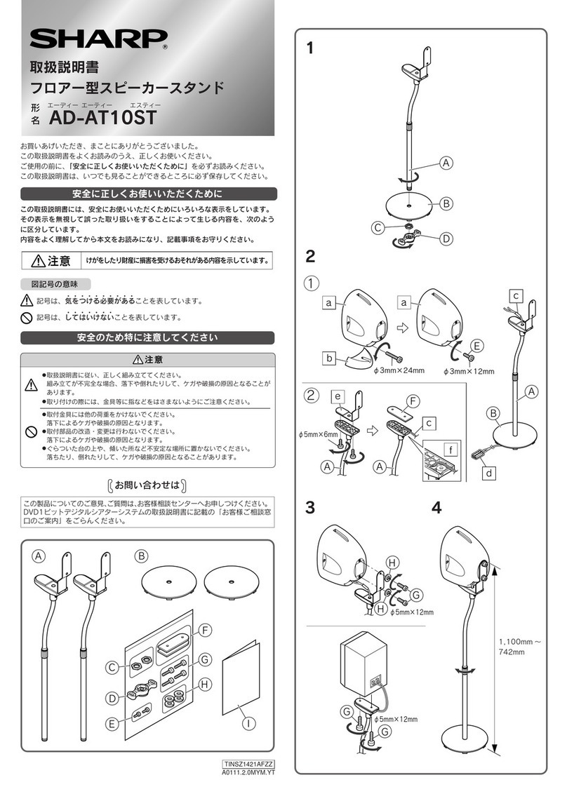
1Remove the nut Cfrom the support pipe A. Turn the pipe Ato assemble
to the bottom plate Band fasten it with the nut C.
Use the supplied wrench Dfor tightening.
2Remove the angle a from the pipe A .
B
b
c
34
AA
ab
3Lead the speaker cable b through the support pipe Afrom the bottom
plate B.
• Lead the speaker cable b through the pipe whilst it is contracted.
• Lead the speaker cable b along the groove on the holder c .
4Attach the angle a again.
TINSZA037SJZZ
04K N YT 1
INSTRUCTION MANUAL
FLOOR SPEAKER STAND
MODEL
AD-AT12ST
Thank you for purchasing this SHARP product.
To obtain the best performance from this product, please read this manual carefully.
It will guide you in operating your SHARP product.
Precautions
Caution:
This floor speaker stand is designed exclusively for SHARP’s SD-AS10
(SD-AS10H/SD-AS10W). Use with other products may result in instability
causing injury.
Mount the speaker observing instructions in this manual.
Ifitisnotmountedproperly, the stand may fall over leading to injury or damage to
the speaker.
Be careful not to pinch your fingers whilst mounting.
Do not put any extra load on the stand. It may cause injury or damage to the
speaker.
Donotmodifyorchangethestand.Itmaycauseinjuryordamagetothespeaker.
Donotplacethesestandsonunstablesurfaceorframe.Theymayfalloverorfall
off, causing injury or damage to the speaker.
Check that the stands are mounted to speakers properly. SHARP is not
liable for accidents caused by improper mounting.
Included parts
AB
G
DF
C
E
ASupport Pipe 2ESpeaker Mounting Screw 4
BBottom Plate 2FSpring Washer 4
CNut 2GInstruction Manual 1
DWrench 1
ENGLISH
Printed in China
Geduckt in China
Imprimé en Chine
Impreso en China

5
6
b
FE
7
1,104 mm –746 mm
(43-1/2" –29-1/2")
5Secure the speaker with the speaker mounting screws Eand spring wash-
ers F.
6Connect the cable b to the speaker.
For speaker connections, refer to the operation manual of the unit.
7Adjust the height of the speaker.
Notes:
A quite heavy load will be applied to the bottom of the stand after the speaker is mounted
on it. Make sure that the position where it is placed is firm and strong enough to support it.
Fasten the screws tight before placing or moving the speaker stand.
Tighten the screws regularly as they may be loosened after mounting
the speaker on it.
If used with the screws loosened, the speaker may fall and cause
injury or damage to people and the speaker itself.
For the speaker direction, refer to the figure.
To adjust the height of the speaker after positioning it, pay attention to cables not to break
them.
Clean the stand with soft cloth dampened with neutral detergent. Never use organic sol-
vents such as benzine, thinner, etc.
Specifications
Load capacity: 1.5 kg (3.3 lbs.) or less
Maximum outside dimensions: 270 mm (W) 1,104 mm (H) 270 mm (D)
(10-11/16”(W) 43-1/2”(H) 10-11/16”(D) )
Weight: Approx. 2.5 kg (5.5 lbs.)
SHARP CORPORATION

DEUTSCH
GEBRAUCHSANLEITUNG
BODEN LAUTSPRECHERSTÄNDER
MODELL
AD-AT12ST
Vielen Dank für den Kauf dieses SHARP-Produktes.
Lesen Sie dieses Handbuch sorgfältig durch, um eine bestmögliche Leistung zu erreichen.
Es führt Sie in den Betrieb dieses Produkts von SHARP ein.
Zur Beachtung
Vorsicht:
Dieser Boden-Lautsprecherständer ist ausschließlich für SD-AS10 (SD-
AS10H/SD-AS10W) von SHARP bestimmt. Bei der Verwendung mit anderen
Produkten kann es zur Instabilität kommen, wodurch Verletzungsgefahr
entsteht.
Beim Montieren des Lautsprechers befolgen Sie die Anweisungen in diesem
Handbuch.
Wenn er nicht richtig montiert wird, kann der Ständer umfallen; es kann zu
Personen- oder Lautsprecherschäden führen.
Beim Montieren darauf achten, daßsich Sie die Finger nicht klemmen.
Keine zusätzliche Last auf den Ständer ausüben. Es kann zu Personen- oder
Lautsprecherschäden führen.
Niemals den Ständer modifizieren oder ändern. Es kann zu Personen- oder
Lautsprecherschäden führen.
DieseStänderaufeineinstabileUnterlageoderRahmen nicht stellen. Sie können
um-oder herunterfallen; es kannzuPersonen- oder Lautsprecherschädenführen.
Prüfen, ob die Ständer an den Lautsprechern richtig montieren sind. Für
Unfälle, die durch falsche Montage verursacht werden, kann SHARP nicht
haftbar gemacht werden.
Mitgelieferte Teile
AStützrohr 2ELautsprecher-Montageschraube 4
BBodenplatte 2FFederring 4
CMutter 2GGebrauchsanleitung 1
DSchraubenschlüssel 1
Montage
1Die Mutter Caus dem Stützrohr Aentfernen. Das Rohr Adrehen, um es
ander Bodenplatte Banzubringen; danach esmit der Mutter Cbefestigen.
Den mitgelieferten Schraubenschlüssel Dzum Festziehen verwenden.
2Das Winkelstück a aus dem Stützrohr Aentfernen.
3Das Lautsprecherkabel b von der Bodenplatte Bdurch das Stützrohr A
führen.
•Das Lautsprecherkabel b durch das Rohr führen, während es zusammengezogen wird.
•Das Lautsprecherkabel b entlang der Rille auf dem Halter c führen.
4Das Winkelstück a erneut montieren.
5Den Lautsprecher mit den Lautsprecher-Montageschrauben Eund
Federringen Fbefestigen.
6Das Kabel b an den Lautsprecher anschließen.
Um die Lautsprecher anzuschließen, beziehen Sie sich auf die Bedienungsanleitung des
Geräts.
7Die Höhe des Lautsprechers einstellen.
Hinweise:
Eine ganz schwere Last wird an den Boden des Lautsprecherständers angelegt, nachdem
derLautsprecher daran montiertworden ist. Sicherstellen,daßdie Position, woeraufgestellt
wird, genug fest und stark ist, um ihn zu stützen.
Vor dem Aufstellen oder Verschieben des Lautsprecherständers die
Schrauben nachziehen.
Die Schrauben regelmäßig nachziehen, da sich sie nach dem
Montieren des Lautsprechers lockern können.
Wenn der Lautsprecher mit gelockerten Schrauben verwendet wird,
kann er fallen; es kann Personenschaden oder Beschädigung des
Lautsprechers verursachen.
Richtung des Lautsprechers siehe Abbildung.
Beim Einstellen der Höhe des Lautsprechers darauf achten, die Kabel nicht zu brechen.
Den Ständer mit einem mit neutralem Waschmittel angefeuchteten, weichen Tuch
abwischen.Keine organischen Lösungsmittel(Benzin,Verdünnungsmittel usw.)verwenden.
Technische Daten
Tragfähigkeit: 1,5 kg oder weniger
Max. Außenabmessungen: 270 mm (B) 1.104 mm (H) 270 mm (T)
Gewicht: ca. 2,5 kg
SHARP CORPORATION
AB
G
DF
C
E
A
B
D
C
C
12
A
a
B
b
c
34
AA
ab
5
6
b
FE
7
1.104 mm –746 mm

ESPAÑOLFRANÇAIS
MODE D’EMPLOI
PIEDS ENCEINTES SATELLITES
MODÈLE
AD-AT12ST
Nousvous remercions d’avoir portévotre choix sur ceproduit SHARP. Pour en tirerle meilleur
parti, veuillez lire ce mode d’emploi très attentivement.
Précautions
Attention:
Ce pied enceinte satellite a étéconçu exclusivement pour le modèle SD-
AS10 (SD-AS10H/SD-AS10W) de Sharp. L’emploi d’autres produits peut
causer une instabilitéqui pourrait provoquer des accidents.
Monterlesenceintes en suivant les instructions données dans ce mode d’emploi.
Dans le cas contraire, le pied risque en tombant de provoquer des accidents
(blessure ou endommagement de l’appareil principal).
Veiller àne pas se pincer le doigt lors du montage.
Ne mettre aucune charge supplémentaire au pied pour éviter tout risque de
blessure ou de casse.
Ne pas modifier ni remplacer le pied pour éviter tout risque de blessure ou de
casse.
Placer les pieds sur un sol ou un socle stable pour éviter tout risque de blessure
ou de casse.
Vérifier que les enceintes sont bien montées aux pieds. SHARP n’est pas
responsable des accidents causés par un mauvais montage.
Pièces fournies
ATuyau de support 2EVis de montage 4
BPlaque de fond 2FRondelle 4
CÉcrou 2 GMode d’emploi 1
DClef 1
Montage
1Retirer l’écrou Cdu tuyau de support A. Tourner le tuyau Apour le
monter sur la plaque Bde fond, puis le fixer avec l’écrou C.
Utiliser la clef fournie Dpour le serrage.
2Retirer la cornière a du tuyau A.
3Faire passer le fil b par le tuyau Aàpartir de la plaque de fond B.
•Passer le fil d’enceinte b dans le tuyau lorsque ce dernier est raccourci.
•Passer le fil d’enceinte b dans la rainure prévue sur le porte-enceinte c .
4Rattacher la cornière a .
5Visser l’enceinte avec les vis de montage Eet les rondelles àressort F.
6Raccorder le câble b àl’enceinte.
En ce qui concerne le raccordement des enceintes, se reporter au mode d’emploi qui
accompagne l’unité.
7Régler la hauteur de l’enceinte.
Notes:
Après le montage, une force élevée s’applique au bas des pieds enceintes. Vérifier que
l’emplacement d’installation est suffisamment robuste pour les supporter.
Bien serrer les vis avant d’installer ou de retirer les pieds enceintes.
Après le montage, les vis peuvent se desserrer. On les resserrera
régulièrement.
En cas d’oubli, les enceintes risquent en tombant de blesser des gens
ou de s’endommager.
Pour l’orientation de l’enceinte, voir l’illustration.
Pour régler la hauteur des enceintes après la mise en place, veiller àne pas couper les fils
d’enceinte.
Nettoyer les pieds avec un chiffon doux imbibéde détergent neutre. Éviter d’employer du
solvant organique (benzène, diluant, etc.).
Fiche technique
Charge admise: 1,5 kg ou moins
Dimensions hors tout: 270 mm (L) 1.104 mm (H) 270 mm (P)
Poids: 2,5 kg environ
SHARP CORPORATION
MANUAL DE MANEJO
PEANA PARAALTAVOZ DE SUBGRAVES
MODELO
AD-AT12ST
Muchas gracias por haber adquirido este producto SHARP.
Lea atentamente este manual para conseguir el mejor rendimiento del aparato. Le servirá
también como guía operativa de este producto SHARP.
Precauciones
Precaución:
Esta peana para altavoz de subgraves estáexclusivamente diseñado para
SHARP SD-AS10 (SD-AS10H/SD-AS10W). El empleo de productos no
especificados puede ocasionar la inestabilidad que causarán heridas.
Monte el altavoz observando las instrucciones dadas en este manual.
Sino se monta correctamente,correráelpeligro de caerse lapeanaque causarán
heridas o daños al altavoz.
Tenga cuidado de no pillarse los dedos durante el montaje.
No imponga ninguna carga extra a la peana. Podría ocasionar heridas o daños
al altavoz.
No modifique ni cambie la peana. Podría ocasionar heridas o daños al altavoz.
Nopongaestaspeanassobreuna superficie inestable ni en un bastidor.Podrían
caerse y causar heridas o daños al altavoz.
Compruebe que los soportes se monten a los altavoces correctamente.
Sharp no se hace responsable de los accidentes causados por el montaje
inadecuado.
Partes incluidas
ATubo de soporte 2ETornillo de montaje de altavoz 4
BPlaca inferior 2FArandela de resorte 4
CTuerca 2GManual de manejo 1
DLlave 1
Montaje
1Saque la tuerca Cdel tubo de soporte A. Gire el tubo Apara montarlo
en la placa inferior By fíjelo con la tuerca C.
Para el apriete, emplee la llave suministrada D.
2Extraiga el angular a del tubo A.
3Pase el cable de altavoz b a través del tubo de soporte Adesde la placa
inferior B.
•Pase el cable de altavoz b por el tubo mientras estácontraído.
•Pase el cable de altavoz b por la ranura del soporte c .
4Fije de nuevo el angular a .
5Fije el altavoz con los tornillos de montaje Ey las arandelas de resorte F.
6Conecte el cable b al altavoz.
En cuanto a la conexiones de los altavoces, consulte el manual de manejo de la unidad.
7Ajuste la altura del altavoz.
Notas:
Se aplicaráuna carga bastante pesada a la parte inferior de la peana después de haber
montado el altavoz. Asegúrese de que la posición sea firme y que sea lo suficientemente
resistente para soportarla.
Aprietebien lostornillos antes de poner o sacar lapeana paraaltavoz.
Aprietelos tornillos de vezen cuando porquepuedenaflojarse después
de haber montado el altavoz.
Si se emplea con los tornillos flojos, correráel peligro de caerse el
altavoz y de ocasionar heridas o daños a la gente y al altavoz.
Para la dirección de la peana, consulte la ilustración.
Para ajustar la altura del altavoz después de haberlo colocado, tenga cuidado para que no
se rompan los cables.
Limpie la peana con un paño blando humedecido en detergente neutro. No emplee nunca
solventes orgánicos tales como la bencina, disolvente, etc.
Especificaciones
Capacidad de carga: 1,5 kg o menos
Dimensiones exteriores máximas: 270mm(An) 1.104 mm (Al) 270 mm (Prf)
Peso: Aprox. 2,5 kg
SHARP CORPORATION
Table of contents
Languages:
Other Sharp Speakers manuals

Sharp
Sharp GX-BT180 User manual

Sharp
Sharp HTSB200 - Sound Bar Speaker User manual

Sharp
Sharp HT-SB400 User manual

Sharp
Sharp XL-G5500V User manual

Sharp
Sharp PS-990 User manual

Sharp
Sharp HT-SL75 User manual

Sharp
Sharp GX-BT280 User manual

Sharp
Sharp CD-C1W User manual

Sharp
Sharp HT-SB95 User manual

Sharp
Sharp CD-C472 User manual

Sharp
Sharp GX-BT3 User manual

Sharp
Sharp GX-BT180 User manual

Sharp
Sharp AD-AT10LS User manual

Sharp
Sharp 32BB1I Technical manual

Sharp
Sharp HT-SB400 User manual

Sharp
Sharp HTSB200 - Sound Bar Speaker User manual

Sharp
Sharp PS-940 User manual

Sharp
Sharp HT-SL75 User manual

Sharp
Sharp AD-AT10ST User manual

Sharp
Sharp HT-SB500 User manual