CD-ES700/CD-ES77
2 – 4
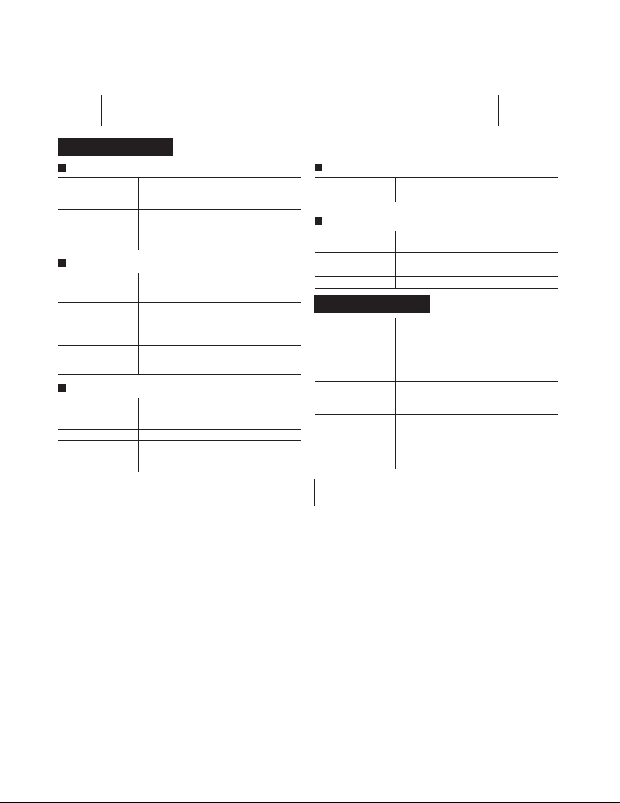
[4] CD section
CD Error code description
* 'CHECKING'
If Error is detected, 'CHECKING' will be displayed instead of 'ER-
CD**'. 'ER-CD**' display will only be displayed when error had been
detected for the 5th times.
Standard Specification of Stereo System Error Message Display Contents
(*) CHECKING:
If CD changer mechanism error is detected, 'CHECKING' will be dis-
play instead of 'ER-CD**'. 'ER-CD**' display will only be display when
error had been detected for the 5 th times.
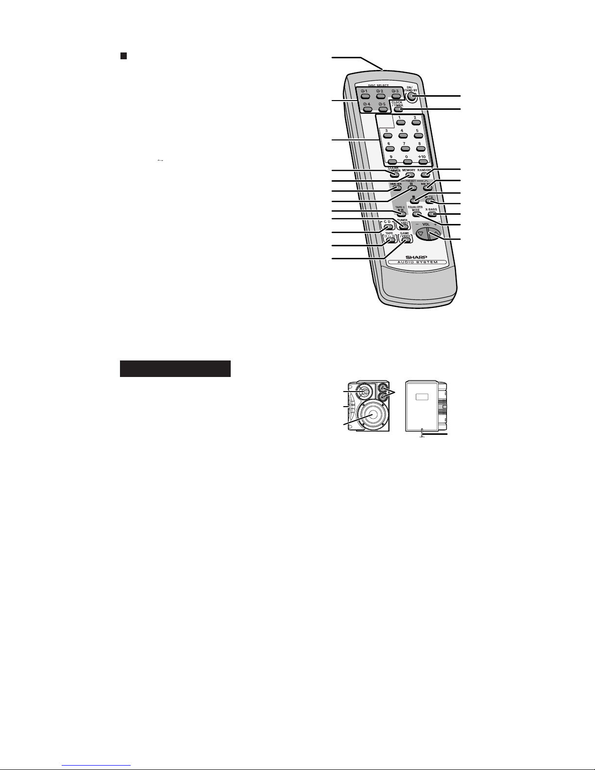
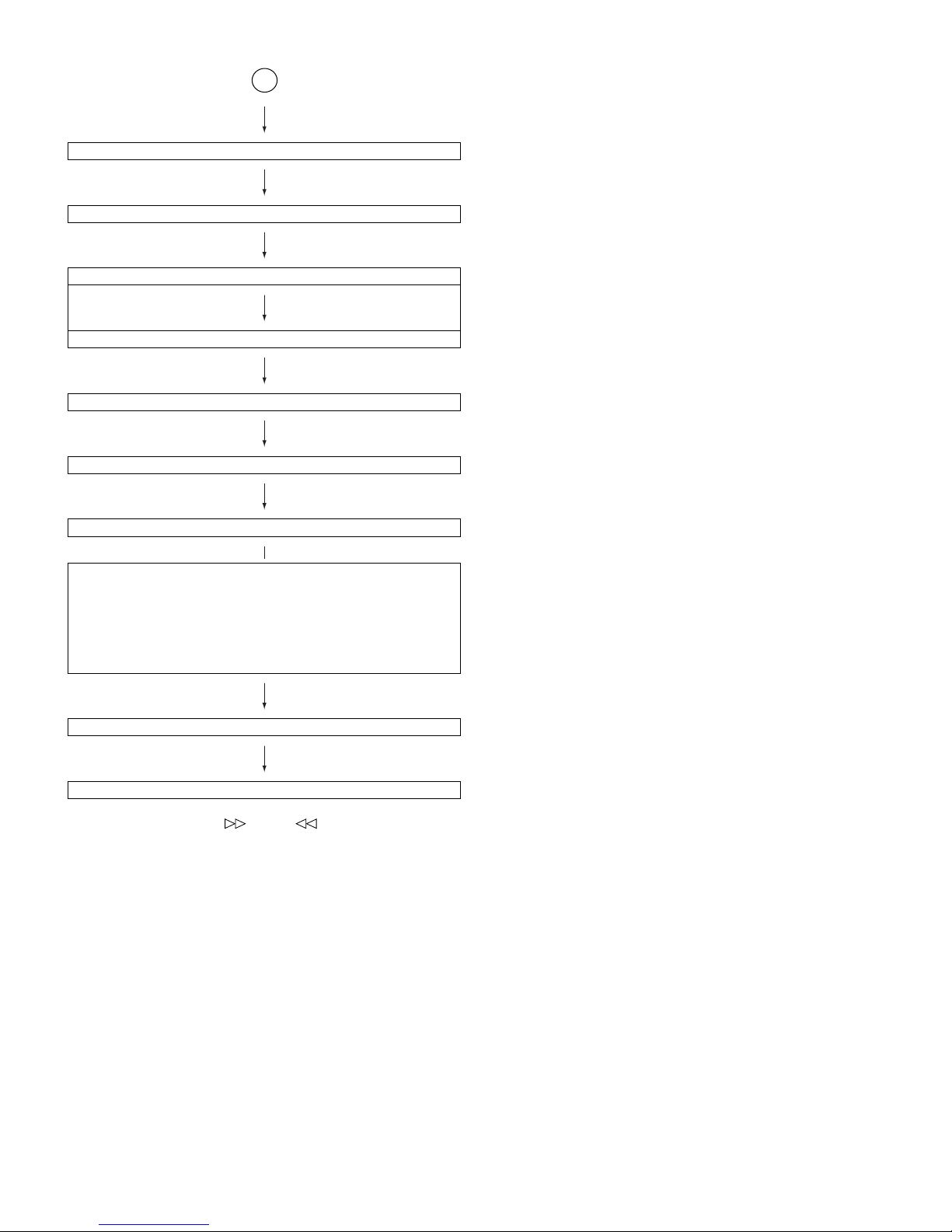
Speaker abnormal detection and +B PROTECTION display
In case speaker abnormal detection or +B PROTECTION had
occurred, it can be check by pressing 'POWER', ' ' and 'X-BASS'
button. MicroComputer version number will displayed as "U*****".
Press ‘VIDEO/AUX’ button during version number display and then
press ‘POWER’, ‘MEMORY/SET’ and ‘VIDEO/GAME’ button. Display
will show "S** B**". S is referring to speaker abnormal detection and B
is referring to +B PROTECTION. ** is in hex valve.
+B PROTECTION is condition when irregular process occur on power
supply line.
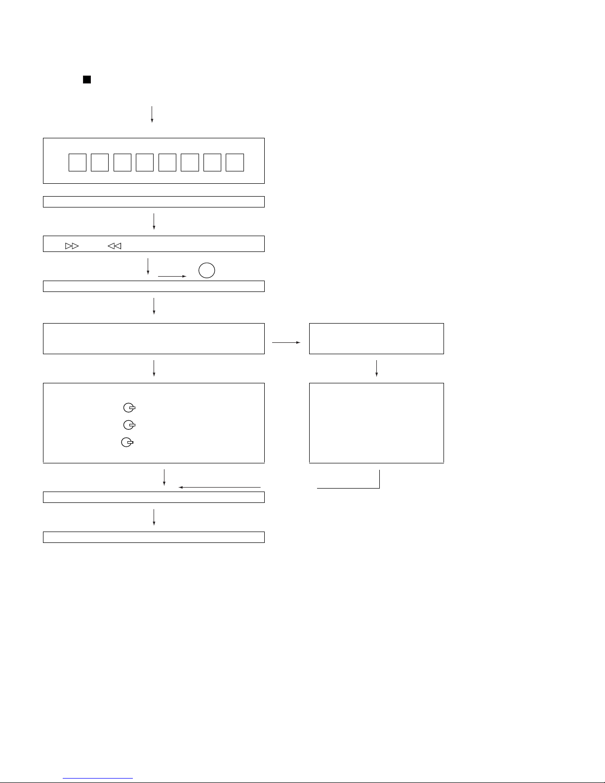
BEFORE TRANSPORTING THE UNIT
The following process need to be taken after set tapering/parts
replacement.
1. Press the ON/STAND-BY button to enter stand-by mode.
2. While pressing down the button and the X-BASS/DEMO but-
ton, press the ON/STAND-BY button. The Micro Computer version
number will be displayed as "U*****".
3. Press OPEN/CLOSE button until "WAIT"→"FINISHED" appears.
4. Unplug the AC cord and the unit is ready for transporting.
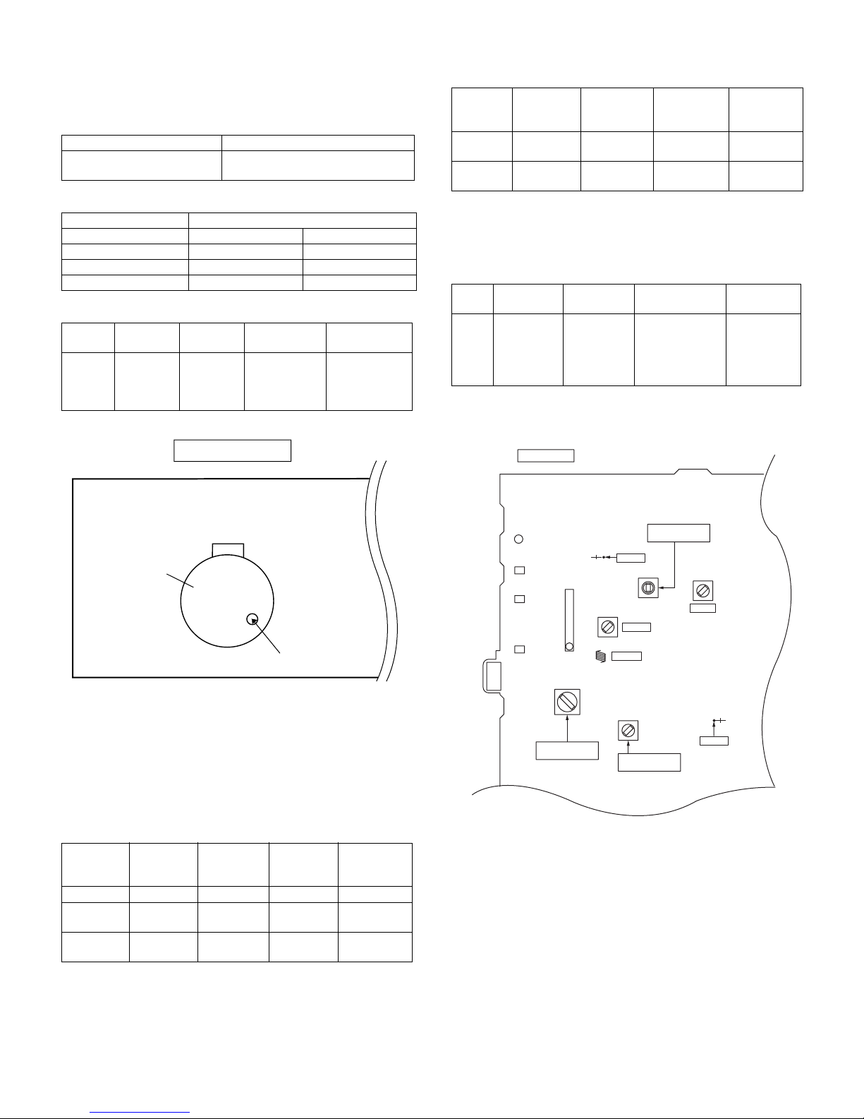
Error Explanation
01 When Pickup set inner position, inner switch cannot detect
'ON' level for 10 secs.
10* CAM error. Can't detect CAM switch when CAM is moving.
11* When it detect cam operation error during initialize pro-
cess.
20* TRAY error. Can't detect TRAY switch when TRAY is mov-
ing.
21* When it detect TRAY operation error during initialize pro-
cess.
31 When it change to CD function, DSP cannot read initial
data.
Error Contents Display Notes
CD Pickup Mechanism Error. 'ER-CD01' PU-IN SW Detection NG.
CD Changer Mechanism Error. 'ER-CD**' (*) 10: CAM SW Detection NG during normal operation
11: CAM SW Detection NG during initialize process
20:TRAY SW Detection NG during normal operation
21:TRAY SW Detection NG during initialize process
CD DSP Communication Error. 'ER-CD31' DSP COMMUNICATION ERROR.
Focus Not Match/IL Time Over. 'NO DISC'
TUNER PLL Unlock. PLL Unlock.
M 87.5 MH


 User manual")

 Instruction manual")