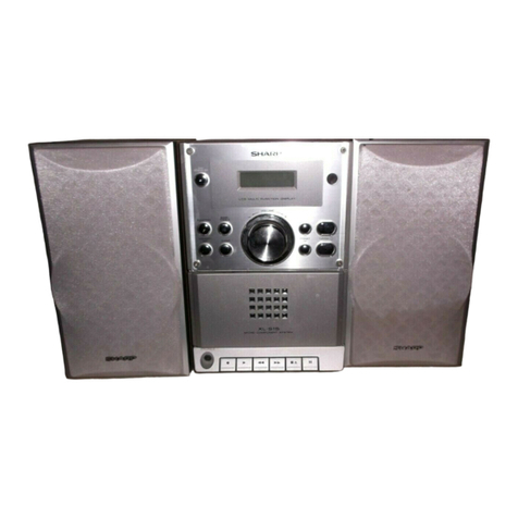
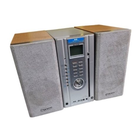
Sharp SD-EX220H User manual

SD-EX220H
CHAPTER 1. GENERAL DESCRIPTION
[1] Specifications.................................................1-1
[2] Names of parts ..............................................1-2
CHAPTER 2. ADJUSTMENTS
[1] Adjustment.....................................................2-1
[2] To Check and Cancel Protect Circuit Detection
Line................................................................2-1
[3] Test mode......................................................2-2
CHAPTER 3. MECHANISM BLOCKS
[1] Disassembly .................................................3-1
[2] Removing and reinstalling the main parts .....3-3
CHAPTER 4. DIAGRAMS
[1] Block diagram................................................4-1
CHAPTER 5. CIRCUIT DESCRIPTION
[1] Notes on schematic diagram.........................5-1
[2] Types of transistor and LED.......................... 5-1
[3] Description of circuit for 1-bit unit (See the wiring
diagrams on pages 6-16 and 6-17)............... 5-2
[4] Waveforms of 1-bit circuit..............................5-2
[5] Waveforms of CD circuit................................ 5-3
[6] Voltage .......................................................... 5-4
CHAPTER 6. CIRCUIT SCHEMATICS AND PARTS
LAYOUT
[1] Wiring side of P.W.Board/schematic diagram 6-1
CHAPTER 7. OPERATION FLOWCHART
[1] Troubleshooting............................................. 7-1
CHAPTER 8. OTHER
[1] Function table of IC....................................... 8-1
Parts Guide
SERVICE MANUAL
No. S7367SDEX220H
1-BIT DIGITAL AUDIO SYSTEM
SD-EX220H
MODEL
SHARP CORPORATION
CONTENTS
Parts marked with " " are important for maintaining the safety of the set. Be sure to replace these parts with specified ones for
maintaining the safety and performance of the set.
This document has been published to be used
for after sales service only.
The contents are subject to change without notice.
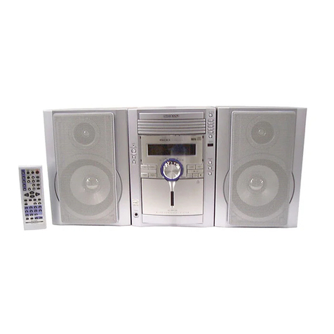
SD-EX220H 1-Bit Digital Audio System consisting of
SD-EX220H (main unit) and CP-EX220H (speaker system).
In the interests of user-safety the set should be restored to its
original condition and only parts identical to those specified be
used.

SD-EX220H
[1] Safety precaution for service manual
Precaution to be taken when replacing and servicing the
Laser Pickup.
The AEL (Accessible Emission Level) of Laser Power Output
for this model is specified to be lower than Class 1 Require-
ments. However, the following precautions must be observed
during servicing to protect your eyes against exposure to the
Laser beam.
(1) When the cabinet has been removed, the power is turned
on without a compact disc, and the Pickup is on a position
outer than the lead-in position, the Laser will light for sev-
eral seconds to detect a disc. Do not look into the Pickup
Lens.
(2) The Laser Power Output of the Pickup inside the unit and
replacement service parts have already been adjusted prior
to shipping.
(3) No adjustment to the Laser Power should be attempted
when replacing or servicing the Pickup.
(4) Under no circumstances look directly into the Pickup Lens
at any time.
(5) CAUTION - Use of controls or adjustments, or performance
of procedures other than those specified herein may result
in hazardous radiation exposure.
[2] Important service notes (For U.K. only)
Before returning the unit to the customer after completion of a
repair or adjustment it is necessary for the following withstand
voltage test to be applied to ensure the unit is safe for the cus-
tomer to use.
Setting of Withstanding Voltage Tester and set.
Laser Diode Properties
Material: GaAIAs
Wavelength: 780 nm
Emission Duration: continuous
Laser Output: max. 0.6 mW
PROBE
AC
OUT
UNIT
SHORT-CIRCUIT
AC POWER
SUPPLY CORD
CONNECT THE PROBE
TO GND OF CHASSIS
SCREW
WITHSTANDING
VOLTAGE TESTER
Set name set value
Withstanding Voltage Tester
Test voltage 4.7 kV DC
Set time 3 secs
Set current (Cutoff current) 3 mA
Unit
Judgment
OK: The ÒGOODÓ lamp lights.
NG: The ÒNGÓ lamp lights and the buzzer sounds.

SD-EX220H
1 – 1
AudioSD-EX220HService ManualMarketE
CHAPTER 1. GENERAL DESCRIPTION
[1] Specifications
General
Amplifier
CD player
Tuner
Power source AC 230 V, 50 Hz
Power consumption Power on: 62 W
Power stand-by: 0.9 W
Dimensions Width: 380 mm (15")
Height: 200 mm (7-7/8")
Depth: 120 mm (4-3/4")
Weight 3.7 kg (8.2 lbs.)
Output terminals Speakers: 4 ohms
Headphones: 16 - 50 ohms (recommended: 32 ohms)
Optical digital output
Subwoofer pre-out (audio signal): 200 mV/10 k ohms at
70 Hz
Input terminals Auxiliary input: 500 mV/47 k ohms
Amplification system 64fs 1-bit switching (Remarks: fs = 44.1 kHz)
Rated output power RMS: 160 W (80W+80W)(DIN 45 500)
A/D noise shaping 7th-order (delta - sigma) modulation
Type 1-disc vertical type compact disc player
Signal readout Non-contact, 3-beam semiconductor laser pickup
D/A converter 24-bit/96 k D/A converter
Frequency response 20 - 20,000 Hz
Dynamic range 101 dB (1 kHz)
Frequency range FM: 87.5 - 108 MHz
AM: 522 - 1,620 kHz
Type 2-way type speaker system
2 cm (13/16") Tweeter
12 cm (4-3/4") Woofer
Maximum input power 160 W
Rated input power 80 W
Impedance 4 ohms
Dimensions Width: 270 mm (10-11/16")
Height: 200 mm (7-7/8")
Depth: 124 mm (4-15/16")
Weight 2.3 kg (5.1 lbs.)/each
SD-EX220H (Except for U.K.)
CP-EX220H (Except for U.K.)
SD-EX220H (For U.K.)
CP-EX220H (For U.K.)
General
Amplifier
CD player
Tuner
Power source AC 230 V, 50 Hz
Power consumption Power on: 62 W
Power stand-by: 0.9 W
Dimensions Width: 380 mm (15")
Height: 200 mm (7-7/8")
Depth: 120 mm (4-3/4")
Weight 3.7 kg (8.2 lbs.)
Output terminals Speakers: 4 ohms
Headphones: 16 - 50 ohms (recommended: 32 ohms)
Optical digital output
Subwoofer pre-out (audio signal): 200 mV/10 k ohms at
70 Hz
Input terminals Auxiliary input: 500 mV/47 k ohms
Amplification system 64fs 1-bit switching (Remarks: fs = 44.1 kHz)
Rated output power RMS: 160 W (80 W + 80 W) (1 % T.H.D.)
A/D noise shaping 7th-order (delta - sigma) modulation
Type 1-disc vertical type compact disc player
Signal readout Non-contact, 3-beam semiconductor laser pickup
D/A converter 24-bit/96 k D/A converter
Frequency response 20 - 20,000 Hz
Dynamic range 101 dB (1 kHz)
Frequency range FM: 87.5 - 108 MHz
AM: 522 - 1,620 kHz
Type 2-way type speaker system
2 cm (13/16") Tweeter
12 cm (4-3/4") Woofer
Maximum input power 160 W
Rated input power 80 W
Impedance 4 ohms
Dimensions Width: 270 mm (10-11/16")
Height: 200 mm (7-7/8")
Depth: 124 mm (4-15/16")
Weight 2.3 kg (5.1 lbs.)/each
FOR A COMPLETE DESCRIPTION OF THE OPERATION OF THIS UNIT, PLEASE REFER
TO THE OPERATION MANUAL.
Specifications for this model are subject to change without prior notice.

SD-EX220H
1 – 2
[2] Names of parts
Front panel
1. CD Cover
2. Remote Sensor
3. Timer Set Indicator
4. Headphone Socket
5. CD Stop Button
6. CD Play/Pause Button
7. Tuner (Band) Button
8. Auxiliary Button
9. Volume Up and Down Buttons
10. CD Cover Open/Close Button
11. CD Track Down or Fast Reverse/Tuning Down Button
12. CD Track Up or Fast Forward/Tuning Up Button
13. Bass/Treble Button
14. On/Stand-by Button
Display
1. Surround Indicator
2. RDS Indicator
3. Radio Text Indicator
4. Traffic Announcement Indicator
5. FM Stereo Mode Indicator
6. Timer Play Indicator
7. Sleep Indicator
8. Dynamic PTY Indicator
9. Traffic Programme Indicator
10. FM Stereo Receiving Indicator
11. CD Memory Indicator
12. Random Play Indicator
13. Function Indicators
14. CD Repeat Play Indicator
15. CD Play Indicator
16. CD Pause Indicator
3
4
5
2
11 12 13
58
97
10 11 13 14
12
3
16
7
8
9
10
4
14
15
16
1
2
6
SD-EX220H
Side panel
1. FM 75 Ohms Aerial Socket
2. Aerial Earth Terminal
3. AM Aerial Terminal
4. Auxiliary Input Sockets
5. Optical Digital Output Socket
6. AC Power Lead
7. Speaker Terminals
8. Subwoofer Pre-output Socket
9. Left Side Cover
10. Right Side Cover
1
2
3
4
5
6
7
8
Left side Right side
910

SD-EX220H
1 – 3
Remote control
1. Remote Control Transmitter
2. CD Play/Pause Button
3. CD Stop Button
4. Cursor/Tuner Preset Buttons
5. RDS Display Button
6. RDS Programme Type/Traffic Information Search Button
7. CD Track Down or Fast Reverse/Tuning Down Button
8. CD Memory Button
9. Programme Clear Button
10. Surround Button
11. Timer Button
12. Enter Button
13. On/Stand-by Button
14. Auxiliary Button
15. CD Play Mode Select Button
16. Bass/Treble Button
17. Tuner (Band) Button
18. RDS ASPM (Auto Station Programme Memory) Button
19. CD Track Up or Fast Forward/Tuning Up Button
20. Volume Up and Down Buttons
21. CD/Tuner Direct Buttons
22. CD Time Display Button
23. Clock Display/Dimmer Button
2
1
3
5
4
7
6
8
10
11
12
16
17
13
14
15
18
20
21
19
9
22
23
Buttons with " " mark in the illustration or highlighted in bold on the list can beop-
erated on the remote control only.
SD-EX220H
CP-EX220H
1. Tweeter
2. Bass Reflex Duct
3. Speaker Grille
4. Woofer
5. Speaker Terminals
5
14
3
2
Speaker grilles are removable:
Make sure nothing comes into contact with
the speaker diaphragms when you remove
the speaker grilles.
Note:
When the speakers are hung on the wall, the
speaker badge reads vertically. In this case,
you can adjust the badge to point the proper
direction by turning it manually.
Badge

SD-EX220H
2 – 1
AudioSD-EX220HService ManualMarketE
CHAPTER 2. ADJUSTMENTS
[1] Adjustment
1. CD section
1.1. Adjustment
Since this CD system incorporates the following automatic adjustment
functions, readjustment is not needed when replacing the pickup.
Therefore, different PWBs and pickups can be combined freely.
Each time a disc is changed, these adjustments are preformed auto-
matically. Therefore, playback of each disc can be preformed under
optimum conditions.
2. 1-bit amp. section
2.1. 1-bit amplifier's output offset voltage adjustment
Adjust VRA100 and VRA101 so that the DC voltage between speaker
terminals + and - is set to 0 ± 5 mV at AC 230 V.
OUTPUT OFFSET LEVEL
ADJUSTMENT POINTS
[2] To Check and Cancel Protect Circuit
Detection Line
1. In this model the microcomputer (IC701) detects
the following malfunctions once power is sup-
plied, and cuts off power from all the parts except
for the circuit driving the microcomputer.
1. Abnormal drop in the output voltage of each regulator
(below approx. 1.5 V)
Power is cut off instantly without display.
2. Output offset over voltage of the 1-bit amplifier
(above approx. DC 2 V)
3. Mains overvoltage of the 1-bit amplifier
(above approx. DC 5.5 A)
Power is cut off instantly without display.
4. Defects in the cooling fan or its drive circuit
(when stopped)
Power is cut off after “FAN LOCK” is displayed.
2. Criteria for abnormality, and checking and cancel-
ling the detection line
2.1. The criteria:
1. The voltage of pin 6 (PROTECT) on IC701.
2. The voltage of pin 32 (OFFSET) on IC701: Low (below approx. 1 V)
(abnormal) and High (above approx. 2.5 V) (normal) .
3. The motor stops when it is above approx. 1 V.
If the voltage of pin 10 (FAN LOCK) on IC701 is not between
approx. 0.21 V and 0.9 V whilst the motor rotation is controlled, it is
judged as abnormal.
2.2. Checking and cancelling the detection line:
Caution: If the PROTECT/OFFSET detection line is disconnected in
case of 1, 2 or 3 above, a protective operation does not function. The
disconnection by output short-circuit of each regulator may cause the
parts or PCBs to burn out and therefore do not disconnect the detec-
tion line when the cause is not identified.
(Power supply can be detected with an oscilloscope or like during
approx. 0.5 seconds after an abnormality is found. Note that the detec-
tion would be difficult with a tester as the voltage rises and falls rap-
idly.)
1. Abnormal drop in the output voltage of each regulator
Connect a measuring device (such as an oscilloscope) to the stabiliz-
ing output of the regulator, and turn on the unit. If the detected voltage
is extremely lower than the voltage on the circuit diagram (below
approx. 1.5 V), the regulator itself or the circuit is defective.
2. Output offset overvoltage of the 1-bit amplifier
Adjust the voltage of the output offset. If a protective operation is still
activated, ICA401 on the 1-bit amplifier could be defective (the detec-
tion circuit of the speaker output DC voltage).
Electronic
Voltage
SO421
AC 230 V
Set
Output:
Speaker Terminal
+
-
VR:0
Input : AUX
L-CH Output
Offset Adjustment
R-CH Output
Offset Adjustment
VRA101
VRA100
1-BIT AMP. PWB
SD-EX220H
2 – 2
[3] Test mode
During POWER OFF Mode, push below each 2 buttons and [POWER] button.
Then enter to each TEST MODE.
Version Display
Other Destination : [ME**** ]
Version Display : ME0701A_ (07: MONTH; 01: DAY; A/B/C (MICOM VERSION)
No. Key Test Mode
1 [SKIP UP] + [VOLUME DOWN] ALL CLEAR (RESET)
2 [CD STOP] + [SKIP UP] BUTTON & DISPLAY TEST
3 [CD PLAY/PAUSE] + [AUX] CD TEST
4 [CD PLAY/PAUSE] + [SKIP UP] CD TRAY AGING TEST
5 [TUNER (BAND)] + [VOLUME DOWN] TUNER PRESET MEMORY CLEAR
6 [TUNER (BAND)] + [VOLUME UP] TUNER PRESET MEMORY FOR PRODUCT
7 [TUNER (BAND)] + [CD STOP] RDS TUN SM
8 [AUX] + [VOLUME UP] AUX TEST

SD-EX220H
3 – 1
AudioSD-EX220HService ManualMarketE
CHAPTER 3. MECHANISM BLOCKS
[1] Disassembly
Caution on Disassembly
Follow the below-mentioned notes when disassembling the unit and reassembling it, to keep it safe and ensure excellent performance:
1. Be sure to remove the power supply plug from the wall outlet before starting to disassemble the unit.
2. Take off nylon bands or wire holders where they need to be removed when disassembling the unit. After servicing the unit, be sure to rearrange the
leads where they were before disassembling.
3. Take sufficient care on static electricity of integrated circuits and other circuits when servicing.
1 Rear Cabinet 1. Screw ...................... (A1) x7
2 Main PWB/ 1. Screw ...................... (B1) x7
Tuner Unit 2. Jack Cover, Left ...... (B2) x1
(Note) 3. Screw ...................... (B3) x4
4. Socket ..................... (B4) x9
5. Flat Cable ............... (B5) x1
3 Front Panel 1. Screw ...................... (C1) x5
2. Hook ........................ (C2) x1
3. Socket ..................... (C3) x1
4 Power PWB 1. Screw ...................... (D1) x6
2. Bracket .................... (D2) x1
5 1-Bit Amp. Unit 1. Screw ...................... (E1) x2
6 Display PWB 1. Screw ....................... (F1) x6
2. Frame Support ......... (F2) x1
3. Screw ....................... (F3) x6
4. Socket ...................... (F4) x2
7
Headphones PWB
1. Screw ...................... (G1) x1
8 Switch PWB 1. Screw ...................... (H1) x1
9 CD Mechanism 1. Screw ....................... (J1) x4
2. Screw ....................... (J2) x2
10 Protect Circuit 1. Screw ...................... (K1) x2
PWB/1-Bit Amp. 2. Socket ..................... (K2) x1
Shield Case 3. Screw ...................... (K3) x2
4. Bracket .................... (K4) x1
5. Screw ...................... (K5) x3
11 1-Bit Amp. PWB 1. Screw ....................... (L1) x3
STEP REMOVAL PROCEDURE
SD-EX220H
Note:
1. After removing the connector for the optical pickup from the
connector, wrap the conductive aluminium foil around the front end
of the connector so as to protect the optical pickup from electro-
static damage.
(A1)x4
φ3x10mm
(A1)x3
φ3x12mm
Rear
Cabinet
Front
Panel
(B1)x2
φ3x8mm
(B3)x1
φ3x10mm
Main PWB
Washer
Tuner Unit
Front Panel
(B4)x5 (B4)x3
(B5)x1
(B4)x1
(B2)x1
(B1)x4
φ3x10mm
(B3)x3
φ3x10mm (B1)x1
φ3x8mm
1-Bit Amp.
Unit
(D2)x1
(C3)x1
(C1)x3
φ3x8mm
(C1)x2
φ3x10mm
(E1)x2
φ3x6mm (D1)x6
φ3x10mm
Power PWB
1-Bit Amp. Unit
(C2)x1
Front
Panel

SD-EX220H
3 – 2
1 Front Panel
1. Net Frame Ass'y ..... (C1) x1
1. Screw ...................... (A1) x6
2 Woofer 1. Screw ...................... (B1) x4
3 Tweeter
2. Screw ...................... (C2) x3
STEP REMOVAL PROCEDURE
CP-EX220H
(F4)x1
(F2)x1
(F1)x6
φ3x10mm
(G1)x1
φ3x10mm
Headphones
PWB
Front Panel
(F4)x1
(F3)x6
φ3x10mm
(H1)x1
φ3x10mm
(J1)x4
φ2.6x10mm
(J2)x2
φ3x10mm
Display PWB
Front Panel
Switch PWB
CD Mechanism
Washer
(K5)x1
φ3x8mm
(K5)x1
φ3x8mm
(K5)x1
φ3x6mm
1-Bit Amp.
Shield Case
Protect
Circuit
PWB
(K3)x2
φ3x6mm
(K4)x1
(K2)x1
(K1)x2
φ3x8mm
(L1)x3
φ3x6mm
1-Bit Amp. PWB
(C1)x1
Rear Cabinet (A1)x6
φ3x12mm
(B1)x4
φ4x12mm
(C2)x3
φ4x12mm
Woofer
Tweeter Front Panel

SD-EX220H
3 – 3
[2] Removing and reinstalling the main parts
1. CD mechanism section
Perform steps 1, 2, 3, 6 and 9 of the disassembly method to remove
the CD mechanism.
1.1. How to remove the pickup unit
1. Remove the mechanism cover, paying attention to the pawls (A1) x
4 pcs.
2. Remove the screws (A2) x 2 pcs., to remove the shaft (A3) x 1 pc.
3. Remove the stop washer (A4) x 1 pc., to remove the gear (A5) x 1
pc.
4. Remove the pickup.
Note
After removing the connector for the optical pickup from the connector
wrap the conductive aluminium foil around the front end of connector
so as to protect the optical pickup from electrostatic damage.
1.2. How to Remove the CD door motor
1. Remove the screws (B1) x 2 pcs.
2. Remove the CD door motor.
Caution
Be careful not to damage the gear.
(If the gear is damaged, noise is heard when searching.)
Pickup Unit
(A2)x2
φ
2.6x6mm
(A1)x4
CD Mechanism
Shaft
(A3)x1
Gear
(A5)x1
Stop Washer
(A4)x1
CD Mechanism
Cover
(B1)x2
φ
1.8x4mm
CD Door Gear Unit Ass'y
CD Door Motor

SD-EX220H
4 – 1
AudioSD-EX220HService ManualMarketE
CHAPTER 4. DIAGRAMS
[1] Block diagram
LED602
LED604
+7.9V
+5V
Q607
ILU_LED
IC608
PST9140
RESET
+5V(VREF)
RESET
Q608
HP_SW
RDS_RDY
RDS_CLK
RDS_DATA
RDS_RST
X_OUT
X_IN
LID SENS
+5V
+5V
VREF
VCC
SECTION
TO MAIN
S_MUTE
RESET
+5V
RX_IN
RM601
GP1UM271
PROTECT
SP_RELAY
POWER
A/D_RESET
P_IN
OFFSET
TO MAIN
SECTION
TO CD
CD_RES
CD_CLK
CD_DI
CD_CE/FLASH
CD_DO
CD_DRF
CD_WRQ
JHP601
HEADPHONES
SECTION
TO MAIN
HP_SW
SECTION
MAIN/TUNER
TUN_DO
TUN_DI
TUN_CLK
TUN_CE
O/C_SW
KEY3
KEY2
KEY1
TUN_SM
SURROUND
VSS
AVSS
4.19 MHz
XL601
-
VF2
-VP
VF1
Q606
-
KEY
SECTION
IC701
IX0557AW
SYSTEM
MICROCOMPUTER
FL DISPLAY
FL601
--
96
30
31
3
2
11
2
3
6
20
28 19
3
9
8
2
1
100
15
95
90
91
92
93
28
556
89
41
34
45
44
7
88
24
98
81
18
40
41
42
43
97
21
32
38 37 36 33
34
35
39
23
22
80
2
1
1
2
TO POWER
SECTION
TO POWER
SECTION
TO POWER
SECTION
IC780
AN78L05
VOLTAGE
REGULATOR
SW601,602,608,615
SW604,606,607
SW609-SW612
SWITCHING
SW771
CD DOOR
OPEN/CLOSE
D781

SD-EX220H
4 – 2
+7.9V
Q84
DIGITAL OUT
CONTROL
LEVEL_CONT
TO 1-BIT AMP./
PROTECT CIRCUIT
SECTION
CNP501
TO DISPLAY SECTION
PROTECT
A/D_RESET
OFFSET PROTECT
TUN_SM
TUN_DO
TUN_CLK
TUN_DI
TUN_CE
TO TUNER UNIT
A_GND
TUN_CE
TUN_DI
TUN_CLK
TUN_DO
TUN_L
VCC_9V
TUN_R
TUN_SM
FM_DET
A_GND
ICT21
LC72723
RDS DECODER
+5V
+9V
QT21
MPXIN
VDDA
VDDD
RDS_DATA
RDS_CLK
RDS_RDY
RDS_RST
RD_RDY
RDCL
RDDA
RST
4.332 MHz
XT21
X_IN X_OUT
DIG_FUNC
R
L
LOUT
A3.3V
ROUT
16MOUT
LRCK
BCK
DATA
L_
C
TUNER
GP351TZ
IC4
DIGITAL OUT
VCONT
REV
FWD
VO5-
VO5+
VO3-
VO3+
VO4-
VO4+
FD0
TDO
+5V
VDD
VVDD
MUTING
Q82
Q2
+7.9V
LID_SENS
VDD5
CONT5
SLDO
SPDO
TIN2
TIN1
FIN2
FIN1
RVDD
XVDD
-
OUT2
OUT1
VCC
IC2
LA6574H
FOCUS/
TRACKING/
DRIVER
SW4
PICKUP IN
M
M
M801
SLED
MOTOR
M802
SPINDLE
MOTOR
IC1
LC78646E
CD SERVO
+3.3V
SPIN/SLED
REG
IN
IC3
LM358D
OP-AMP.
VCC
DATA
BCK
LRCK
16MOUT
CONT3
CONT2
VCONT
FD0
TD0
VREF
LDD
PD
ADAVDD
LVDD
RFVDD
XOUT
XIN
XL1
16.9344 MHz
Q1
LASER DRIVER
+3.3V
M
-
+
Q3
CONSTANT
VOLTAGE
VREF
-
+
+
IC101
CS4340KS
DAC IC
FOCUS COIL
TRACKING COIL
PICK UP UNIT
CD_WRQ
CD_DRF
CD_CE
CD_DO
CD_DI
CD_CLK
CD RES
CE
CLK
DI
DO
WRQ
RES
DRF
1
65
8
19
14
11
26
66
37
8
40
43
44
18
3332 343125242322
10
24
9
79
49
3
4
201918
51
12
1
6
45
22
23
20
7
61
76
41
64
39
3
69
234
25436
71
50
710 3 11
27
2
3
67
48
57
68
54
8
26
75
4647
19
5
13
14 1615
4
14
302129
13
60
15
17
28
11
22
56
2
1
59
21
80
63
21
11
5
2
89 11
21
25
28
15
12
8
9
9
8
10
70
62
3877
55
282726
58
1
2
43
72
1017
5
H/P_SW
S-MUTE
716
M1
CD DOOR
MOTOR
+7.9V
-5.6V
+9V

SD-EX220H
4 – 3
CNPS01 BIS01
CNS531
CNPS02
ZD402
ZD400
ZD401
TO MAIN SECTION
TO MAIN SECTION
MUTING
Q544
Q543
SP_RELAY
AD_RESET
OFFSET_PROTECT
OFFSET_COMPA
D+5V
QS01
QS08
QS07
QS06
QS02
QS03
QS04
QS05
QS10
QS14 QS13
QS12 QS11
TO 1-BIT AMP. SECTION
SO421
SPEAKER
TERMINAL
FAN_LOCK
FAN_MOTOR
Q422
Q421
Q423 +
-
M
Q424
TO PROTECT CIRCUIT SECTION
+12V
-9V
+4.7V
-5.6V
A_-20V
+5.1V
+3.3V
A_+20V
+7.9V
+9V
IC400
KIA7812AP
VOLTAGE
REGULATOR
IC402
KIA7808AP
VOLTAGE
REGULATOR
IC401
KIA7809AP
VOLTAGE
REGULATOR
Q551
Q552
CNP501
TO DISPLAY SECTION
S_MUTE
SURROUND
SP_RELAY
H/P_R_OUT
H/P_L_OUT
UNIT
TUN_CE
TUN_DI
TUN_CLK
TUN_DO
TUN_L
IC501
LC75341M
AUDIO PROCESSOR
VDD BASS
L_CH
R_CH
ÑVCC
+VCC
Q536
Q535
Q550 Q549
Q581
Q538
Q545
Q546
Q539
Q540
Q547
Q548
MUTING
HEADPHONE
SURROUND
ON/OFF SYSTEM
MUTE
R_CH
L_CH
MUTING
SURROUND
SURROUND
ON/OFF
GND
L
R
L_CH R_CH
JT501
AUX INPUT
L
R
AUX
TUN_LTUNER
TUN_R
R
LCD
IC502
NJM4565M
BUFFER AMP.
+9V
DI CE
CLK
23
12
67 11
24
13
5
4
10
9
16
1
3
8
7
1714
21
21
4
15
6
2
13
3
15
205
689 1110
6543211234
1234
1234
311
1
3
3
22
2
+
+
-
-
RL421
BASS
CONTROL
SWITCHING
SWITCHING
A/D RESET
SWITCHING
OFFSET
SWITCHING
OFFSET
SWITCHING
A/D RESET
SWITCHING
A/D RESET
SWITCHING
CURRENT
DETECT
CURRENT
DETECT
CURRENT
DETECT
CURRENT
DETECT
SWITCHING
FAN
SWITCHING
FAN
SWITCHING
FAN
SWITCHING
RELAY
SWITCHING
8
4
321
567
MUTING
MUTING
MUTING
DRIVER
-5.6V
+9V
M401
FAN MOTOR
TO 1-BIT AMP.
SECTION
IC503
TJM4558CD
OPE AMP.
JK500
SUBWOOFER
OUT

SD-EX220H
4 – 4
R-CH OUTPUT
OFFSET
ADJUSTMENT
L-CH OUTPUT
OFFSET
ADJUSTMENT
24
23
22
21
20
17
16
15
14
11
10
9
8
7
6
5
4
3
2
1
CXA100
LFA402
LFA403
CNA100
DA404
8
4
11 10 9
12 13 14
1
7
11 10 9
12 13 14
4
3
2
1
7
6
5
4
3
2
1
CNA101
TO MAIN SECTION
TO POWER SECTION
AMP_VCC
A+5V
D+5V
D+5VA+5V
QA400QA416QA414QA415
RCH_1
LCH_1
COMPA
OFFSET
11.2896 MHz
A+5V
AGND_AD
DGND_AD
D+5V
VCC
GND
VKK
VKK
INB
INA
VKK
VKK
GND
VCC
INB
INA
L-CH_IN 1
AGND 1
R-CH_IN 1
PROTECT
PROTECT
OFFSET
RESET
NFR1(+)
NFL2(-)
NFL1(+)
NFR2(-)
GNDA
R-CH IN
L-CH IN
RESET
VDA VDDL
GNDD
OUTL(+)
OUTL(-)
OUTR(-)
OUTR(+)
VDDR
VDDX
XI
XO
GNDX
ANALOG IN R-CH
ANALOG IN L-CH
3
2
1
VDD
VSS
ICA100
IX0498AW
7TH ORDER Æ·
MODULATION
CONVERSION LSI
PROTECT
DETECT
PROTECT
DETECT
PROTECT
DETECT
CURRENT
SENSOR
VRA101
VRA100

SD-EX220H
4 – 5
BIA103
LFA101
DA107 DA116
LFA100
A
404 ICA401
TJM4558CD
8
4
LFA400
ICA102
SLA5515M
SWITCHING AUDIO
POWER AMP.
ICA101
SLA5515M
SWITCHING AUDIO
POWER AMP.
PSA400
11 10 9 8 7 6 5 4 3 2 1
12 13 14 15 16 17 18 19 20 21
123
765
11 10 9 8 7 6 5 4 3 2 1
12 13 14 15 16 17 18 19 20 21
5
4
3
1
6
5
4
3
1
BIA104
TO PROTECT SECTION
FROM POWER SECTION
OPE AMP.
OFFSET VOLTAGE
DETECTOR
OFFSET VOLTAGE
DETECTOR
AMP_VCC
+B_AMP
GND
+B
M
Hz
GND
VBOOTAVBOOTB
DTADJA
OUTB
VBBB
DTADJB
OUTB
SA
VCC
SB
GND
VKK
VKK
OUTA
VDD
INB
OUTA
VBBAVBBB
INA
VBBA
VKK
VKK
GND
SB
VCC
SA
OUTB
DTADJB
VBBB
OUTB
DTADJA
VBOOTB VBOOTA
VDD
VBBB
INB
OUTA
VBBA
INA
VBBA
OUTA
L-CH_+1
L-CH_-1
R-CH_-1
R-CH_+1
DRIVER_+9V
+B
2
1
23
1
3
1
2
VDD
VSS
-
+
-
+

SD-EX220H
4 – 6
D938
D908
D942
D937
D930
ZD933
IC931
SE-B2 2
IC933
KIA7809AP
31
IC934
KIA78L05
31
D944
D939
B1900
PC902
BI932
D901
IC901
STRF6267
5
2
1
D902
T903
SUB POWER TRANSFORMER
D950
D953
D951
D952
L902
AC LINE
FILTER
AC POWER
SUPPLY CORD
L901
AC LINE
FILTER
F901
CNP901
CNS901
T901
MAIN POWER TRANSFORMER
CNP934
ZD931
CNP931
PC901
22
1
3
3
4
1
3
POWER
+B_CHK
Q931
-VP
-VF1
-VF2
Q933
+40V
+40V
DRIVER_+9V
A_-20V
VOLTAGE
REGULATOR
A_+5V
D_+5V
AMP.
ERROR
REGULATOR
VOLTAGE
SWITCHING REGULATOR
Q902
A_+20V
A_+20V
D5.6V (UNSW)
SUB TRAN +B
TO DISPLAY SECTION
TO 1-BIT AMP. SECTION
TO 11BIT AMP. SECTION TO MAIN SECTION
FB/SYNC
Drain
T3.15A L 250V
SYNC
OCP
GND
Vin
1
4
3
2
1
32
41
32
41
8
7
6
5
4
2
9
10
2
3
4
5
6
7
8
9
10
3
5
4
2
11
AC 230V, 50 Hz
12
12
SWITCHING
VOLTAGE
REGULATOR
SWITCHING

SD-EX220H
5 – 1
AudioSD-EX220HService ManualMarketE
CHAPTER 5. CIRCUIT DESCRIPTION
[1] Notes on schematic diagram
•Resistor:
To differentiate the units of resistors, such symbol as K and M are
used: the symbol K means 1000 ohm and the symbol M means
1000 kohm and the resistor without any symbol is ohm-type resis-
tor. Besides, the one with “Fusible” is a fuse type.
• Capacitor:
To indicate the unit of capacitor, a symbol P is used: this symbol P
means pico-farad and the unit of the capacitor without such a sym-
bol is microfarad.
As to electrolytic capacitor, the expression “capacitance/withstand
voltage” is used.
(CH), (TH), (RH), (UJ): Temperature compensation
(ML): Mylar type
(P.P.): Polypropylene type
• Schematic diagram and Wiring Side of P.W.Board for this model are
subject to change for improvement without prior notice.
• The indicated voltage in each section is the one measured by Digi-
tal Multimeter between such a section and the chassis with no sig-
nal given.
1. In the tuner section,
indicates AM
indicates FM stereo
2. In the main section, a tape is being played back.
3. In the deck section, a tape is being played back.
( ) indicates the record state.
4. In the power section, a tape is being played back.
5. In the CD section, the CD is stopped.
• Parts marked with “ ” ( ) are important for main-
taining the safety of the set. Be sure to replace these parts with
specified ones for maintaining the safety and performance of the
set.
[2] Types of transistor and LED
REF NO. DESCRIPTION POSITION
SW4 PICKUP IN ON-OFF
SW601 VOLUME DOWN ON-OFF
SW602 VOLUME UP ON-OFF
SW604 SKIP/TUNING UP ON-OFF
SW606 AUX ON-OFF
SW607 TUNER (BAND) ON-OFF
SW608 STOP ON-OFF
SW609 ON/STAND-BY ON-OFF
SW610 OPEN/CLOSE ON-OFF
SW611 BASS/TREBLE ON-OFF
SW612 SKIP/TUNING DOWN ON-OFF
SW615 PLAY/PAUSE ON-OFF
SW771 CD DOOR OPEN/CLOSE ON-OFF
2SB709 AR
2SD601 AR
KRA102 S
KRC102 S
KRC104 S
KRC107 S
KTA1504 GR
KTC3875 GR
AG01Z
AK09
DS1SS133
EK19
D1NL20U
B
(3)
E
(1)
C
(2)
TOP
VIEW
KDS226
MA132WA
MA132WK
TOP VIEW
TOP VIEWTOP VIEW
2SK246 GR
KTA1023 Y
KTA1266 GR
KTA1270 Y
KTA1271 Y
KTC2874 B
VIEW
FRONT
ECB
VIEW
FRONT
123
(S)(G)(D)
(1)(2)(3)
SFPW56
GD1N4004
MA111
D5SB60
AC AC
VIEW
FRONT
FRONT
VIEW
304BC2E9
304VT2E2
A503BC2E
SARS03
KTC3199 GR
KTC3203 Y
KRA107 M
KRC102 M
KRC104 M
KRC107 M
VIEW
FRONT
Cathode Anode
FMLG12S
1. Anode
2. No Contact
3. Cathode

SD-EX220H
5 – 2
[3] Description of circuit for 1-bit unit (See the wiring diagrams on pages 6-16 and 6-17)
Input section
Signals from CNA101 are coupled by CA100 and CA101 and then sent
into the A/D converter IC (ICA100).
∆Σ modulation 1-bit converter
Signals from the A/D converter IC (ICA100) are converted to 1-bit sig-
nals and sent differentially. Refer to the technical manual of SM-SX100
for the details of conversion to 1-bit signals.
Low pass filter circuit
1-bit signals switched by the output IC (ICA101 and ICA102) are con-
verted to analog signals through the lowpass filter consisting of LA101
~ LA107. The low pass filter functions when a frequency exceeds 20
kHz, and reduces it by approx. 3 dB when it reaches approx. 40 kHz.
Dynamic feedback circuit
The 1-bit signals switched by the output IC (ICA101 and ICA102) oscil-
late between positive and negative voltage. After resistance-division,
the signals are fed back to the A/D converter IC (ICA100) through NF
resistance 75 kohms (RA155 ~ RA158). The peak-to-peak voltage
reaches approx. 5 V.
[4] Waveforms of 1-bit circuit
T
2
1
2.00V/div
500 ns/div 194.545465 µs 520 mV
2.00V/div
AD IC Output + Side
- Side
5V
Amplitude
from0to5V
1
2
2
1
2.00 V/div
500 ns/div 194.545465 µs -12.30 V
2.00 V/div
AD IC NF IN
In partial pressure OUT, 4 to 7 V amplitude
of GND reference is observed.
In IC of 75 kohms, the reference is 2.5 V
because of VREF. Due to imaginary GND
of operational amplifier inside IC, the
waveform cannot be monitored.
This waveform is partial pressure OUT.
3
4
T
2.00 V/div
50.0 ns/div 0.0 s -12.30 V
2.00 V/div
LEVEL SHIFT OUT
DEAD TIME
ZOOM UP
Dead time is generated by level
shift input.
Leading edge is delayed at CR,
passing R at DI.
Set value: 20 - 25 nsec.
5
6
T
10.0 V/div
500 ns/div 194.545465 µs -12.3 V
10.0 V/div
+ SIDE
+ FETOUT
- SIDE
Waveforms before low-pass filters at both
ends of the speaker.
H-bridge may be considered as BTL.
However, here and at the gate drive, dead
time is not observed; since bootstrap
operates based on output, DEAD TIME
part is in floating condition. The waveform
on the HIGH side shows that only the
booted voltage lowers.
2
1
11
12

SD-EX220H
5 – 3
[5] Waveforms of CD circuit
T
FDO
TDO
Stopped
CH1=500 mV
DC 10:1
CH3=500 mV
DC 10:1
500 ms/div
(500 ms/div)
NORM:20 kS/s
1
3
=Record Length=
Smoothing : ON CH1 : 0.000 V
CH2 : 0.0 V
Main : 100 K
Zoom : 2 K
Mode : AUTO
Type : EDGE CH1
Delay : 0.0 ns
Hold off : 0.2 µs
CH3 : 0.000 V
CH4 : 0.00 V
BW : FULL
=Trigger==Filter= =Offset=
CH1
v/DIV
500 mV
1IC1 21
2IC1 20
T
FDO
DRF
TE
Stopped
CH1=500 mV
DC 10:1
CH2=10 V
DC 10:1
CH3=1 V
DC 10:1
500 ms/div
(500 ms/div)
NORM:20 kS/s
1
2
3
=Record Length=
Smoothing : ON CH1 : 0.000 V
CH2 : 0.0 V
Main : 100 K
Zoom : 2 K
Mode : AUTO
Type : EDGE CH1
Delay : 0.0 ns
Hold off : 0.2
µ
s
CH3 : 0.00 V
CH4 : 0.00 V
BW : FULL
=Trigger==Filter= =Offset=
-3 div -1 div 0 div +1 div +3 div
CH Position To
CH2
Position
0.20 div
1
IC1 21
3
IC1 67
4
IC1 15
T
T
TE
DRF
Stopped
CH1=10 V
DC 10:1
CH2=1 V
DC 10:1
100 ms/div
(100 ms/div)
NORM:100 kS/s
2
1
=Record Length=
Smoothing : ON CH1 : 0.0 V
CH2 : 0.00 V
Main : 100 K
Zoom : 2 K
Mode : NORMAL
Type : EDGE CH1
Delay : 2.924 ms
Hold off : 0.2 µs
CH3 : 0.00 V
CH4 : 0.00 V
BW : FULL
=Trigger=
=Filter= =Offset=
3
IC1 67
4
IC1 15
Vp-p=1.0 V~1.3 V
0.5 mV/div,0.5 µsec/div
5IC1 4
T
T
FDO
SPDO
Stopped
CH1=200 mV
DC 10:1
CH2=500 mV
DC 10:1
500 ms/div
1999/04/07 09:51:15
(500 ms/div)
NORM:20 kS/s
2
1
=Record Length=
Smoothing : ON CH1 : 0.000 V
CH2 : 0.000 V
Main : 100 K
Zoom : 2 K
Mode : NORMAL
Type : EDGE CH2
Delay : 2.924 ms
Hold off : 0.2 µs
CH3 : 0.00 V
CH4 : 0.00 V
BW : FULL
=Trigger=
=Filter= =Offset=
1
IC1 21
6
IC1 22
T
FDO
PDO2
PDO1
Stopped
CH1=500 mV
DC 10:1
CH3=1 V
DC 10:1
CH4=1 V
DC 10:1
500 ms/div
(500 ms/div)
NORM:20 kS/s
1
4
3
=Record Length=
Smoothing : ON CH1 : 0.000 V
CH2 : 0.0 V
Main : 100 K
Zoom : 2 K
Mode : AUTO
Type : EDGE CH2
Delay : 0.0 ns
Hold off : 0.2 µs
CH3 : 0.00 V
CH4 : 0.00 V
BW : FULL
=Trigger==Filter= =Offset=
CH1
v/DIV
500 mV
1999/04/05 17:33:17
1
IC1 21
7
IC1 73
8
IC1 74
T
T
DOUT
Stopped
CH1=2 V
DC 10:1
500 ns/div
1999/04/07 09:25:28
(500 ns/div)
NORM:200 MS/s
1
=Record Length=
Smoothing : ON CH1 : 0.00 V
CH2 : 0.00 V
Main : 1 K
Zoom : 100
Mode : NORMAL
Type : EDGE CH1
Delay : 2.887 ms
Hold off : 0.2
µ
s
CH3 : 0.00 V
CH4 : 0.00 V
BW : FULL
=Trigger=
=Filter= =Offset=
9IC1 39
T
T
DATA
DATACK
LRSY
Stopped
CH1=2 V
DC 10:1
CH2=2 V
DC 10:1
CH3=2 V
DC 10:1
5 µs/div
(5 µs/div)
NORM:100 kS/s
1
2
3
=Record Length=
Smoothing : ON CH1 : 0.00 V
CH2 : 0.00 V
Main : 5 K
Zoom : 100
Mode : AUTO
Type : EDGE CH3
Delay : 0.0 ns
Hold off : 0.2 µs
CH3 : 0.00 V
CH4 : 0.00 V
BW : FULL
=Trigger==Filter= =Offset=
CH3
v/DIV
2V
1999/04/05 20:50:17
10 IC1 58
IC1 59
IC1 60
11
12

SD-EX220H
5 – 4
[6] Voltage
PIN NO. VOLTAGE
10V
0V
2
30V
40V
4.52 V
5
6 4.57 V
4.50 V
7
8 4.50 V
9 4.50 V
10 4.50 V
11 4.50 V
12 4.50 V
13 4.50 V
14 4.50 V
15 4.50 V
16 4.50 V
17 4.52 V
18 4.50 V
19 4.50 V
20 4.52 V
21 4.52 V
22 4.52 V
23 9 V
24 0 V
IC501
PIN NO. VOLTAGE PIN NO. VOLTAGE
1 5.05 V 51 0 V
2 5.05 V
0V
52
53
54
0V
3
4
5 0.81 V
0V
55 0 V
0V
0V
6 5.09 V 56 0 V
7 2.26 V 57 25.99 V
8 2.38 V
0V
58
59
-25.99 V
-25.99 V
9
10 0 V 60 -25.99 V
11 5.21 V 61 -25.99 V
12 0 V 62 0 V
13 0 V 63 -25.99 V
14 2.39 V 64 0 V
15 4.76V 65 0 V
16 0 V 66 -22.76 V
17 0 V 67 0 V
18 4.79 V 68 0 V
19 4.69 V 69 0.32 V
20 4.85 V 70 0 V
21 0 V 71 1.01 V
22 2.16 V 72 25.99 V
23 2.30 V 73 0 V
24 4.87 V 74 0 V
25 0 V 75 25.89 V
26 0 V 76 0 V
27 0. V 77 25.98 V
28 4.87 V 78 0 V
29 0 V 79 22.66 V
30 0 V 80 0 V
31 5.05 V 81 22.80 V
32
33
5.12 V 82 -22.46 V
4.87 V 83 -22.56 V
34 3.79 V 84 -22.50 V
35 4.24 V 85 -0.10 V
36 1.10 V 86 -22.73 V
37 4.41 V 87 -22.73 V
38 0 V 88 -22.48 V
39 4.86 V 89 25.89 V
40 0 V 90 0 V
41 0 V 91 0 V
42 0 V 92 0 V
43 5.23 V 93 0.51 V
44 0 V 94 0 V
45 4.86 V 95 0 V
46 0 V 96 4.87 V
47 0 V 97 0 V
48 0 V 98 5.05 V
49 0 V 99 0 V
50 0 V 100 5.05 V
IC701
PIN NO. VOLTAGE
1 2.66 V
0.60 V
10.18 V
3
2
PIN NO. VOLTAGE
E0V
C 4.79 V
B0V
Q606
IC780
PIN NO. VOLTAGE
1 5.09 V
5.08 V
0V
3
2
PIN NO. VOLTAGE
E0V
C 4.80 V
B0V
Q608
IC608
PIN NO. VOLTAGE
E0V
C 0.26 V
B 4.80 V
Q607
PIN NO. VOLTAGE
E 7.95 V
C 3.30 V
B 7.28 V
Q3
PIN NO. VOLTAGE
E 1.66 V
C 1.66 V
B 5.40 V
Q82
PIN NO. VOLTAGE
E0V
C 3.28 V
B0V
Q101
PIN NO. VOLTAGE
1 1.62 V
2
3
4
1.07 V
1.06 V
0.50 V
5
6
3.29 V
15.33 V
7
8
9
1.66 V
1.66 V
1.66 V
10 1.66 V
11 1.67 V
12 1.66 V
13 0 V
14 1.23 V
15 0 V
16 0 V
17 0 V
18 3.29 V
19 0 V
20 1.65 V
21 1.65 V
22 1.65 V
23 1.65 V
24 1.65 V
25 3.84 V
26 3.29 V
27 3.30 V
28 3.76 V
29 0 V
30 3.30 V
31 0 V
32
33
0V
0V
34 0 V
35 0 V
36 0 V
37 0 V
38 3.29 V
39 0 V
40 0 V
41 3.85 V
42 0 V
43 0 V
44
45
0V
0V
46 3.85 V
47 3.30 V
48 3.39 V
49 0 V
50 0 V
51 0 V
52 0 V
53 0 V
54 3.30 V
55 0 V
56 0 V
57 0 V
58 0 V
59 0 V
60 0 V
61 3.85 V
62 0 V
63 0 V
64 0 V
65 0 V
66 3.85 V
67 3.29 V
68 3.30 V
69 0 V
70 0 V
71 0 V
72 0 V
73 0 V
74 3.30 V
75 0 V
76 0 V
77 0 V
78 0 V
79 0 V
80 0 V
IC1
PIN NO. VOLTAGE
1
2
3
7.87 V
0V
0V
3.55 V
3.62 V
3.60 V
3.57 V
4
5
6
7
83.55 V
3.63 V
9
10 3.54 V
11 3.54 V
12 7.89 V
13 1.66 V
14 1.66 V
15 1.67 V
16 1.67 V
17 1.65 V
18 1.67 V
19 7.20 V
20 0 V
21 1.67 V
22 7.87 V
23 1.67 V
24 1.67 V
25 3.88 V
26 0 V
27 4.78 V
28 4.78 V
IC2
PIN NO. VOLTAGE
1
2
3
4
5
2.25 V
0.25 V
0.25 V
0V
2.26 V
6 2.26 V
7 2.26 V
8 6.21 V
IC3
PIN NO. VOLTAGE
1
2
3
4
5
-14.90 V
0V
0V
0V
14.86 V
60V
70V
80V
IC502 PIN NO. VOLTAGE
1
2
3
4
5
0V
0V
0V
-5.24 V
0V
60V
70V
8 8.53 V
IC503
PIN NO. VOLTAGE
1 3.28 V
0V
0V
0V
3.30 V
2
3
4
5
6 3.30 V
7 3.30 V
80V
0V
9
10 1.78 V
11 0 V
12 0 V
13 0 V
14 0 V
15 0 V
16 3.64 V
IC101
PIN NO. VOLTAGE
1 2.14 V
2.13 V
4.30 V
0V
2.14 V
2
3
4
5
6 2.12 V
70V
8 2.19 V
2.09 V
9
10 0 V
11 4.30 V
12 4.30 V
13 0 V
14 0 V
15 0 V
16 0 V
ICT21
PIN NO. VOLTAGE
E 3.30 V
C0V
B 3.28 V
Q1
PIN NO. VOLTAGE
E 2.90 V
C 3.21 V
B 7.25 V
Q84
PIN NO. VOLTAGE
E 4.89 V
C 5.56 V
B 7.46 V
Q2
PIN NO. VOLTAGE
1 19.02 V
20V
3 8.94 V
IC401 PIN NO. VOLTAGE
1 19.03 V
20V
3 11.90 V
IC400
PIN NO. VOLTAGE
1 19.02 V
20V
3 7.95 V
IC402
PIN NO. VOLTAGE
E 8.95 V
C 5.87 V
B 8.91 V
Q536
PIN NO. VOLTAGE
E0V
C 5.64 V
B0V
Q538
PIN NO. VOLTAGE
E0V
C0V
B 0.65 V
Q539
PIN NO. VOLTAGE
E0V
C 5.02 V
B0V
Q400
PIN NO. VOLTAGE
1 9.00 V
20V
3 5.09 V
IC934
PIN NO. VOLTAGE
1 20.20 V
20V
3 9.00 V
IC933
PIN NO. VOLTAGE
1 6.92 V
2 35.10 V
30V
IC931
PIN NO. VOLTAGE
E 2.29 V
C 2.26 V
B0V
Q545
PIN NO. VOLTAGE
E0V
C0V
B 0.69 V
Q547
PIN NO. VOLTAGE
E0V
C0V
B 0.69 V
Q548
PIN NO. VOLTAGE
E -26.30 V
C -54.90 V
B -26.60 V
Q931
PIN NO. VOLTAGE
E0V
C 0.55 V
B0V
Q933
PIN NO. VOLTAGE
E0V
C 5.35 V
B0V
Q535
PIN NO. VOLTAGE
E 2.29 V
C 2.25 V
B 1.65 V
Q546
PIN NO. VOLTAGE
E0V
C0V
B 6.11 V
Q421
PIN NO. VOLTAGE
E0V
C0V
B 0.66 V
Q540
PIN NO. VOLTAGE
E0V
C 11.90 V
B0V
Q424
PIN NO. VOLTAGE
E0V
C 6.11 V
B0V
Q422
PIN NO. VOLTAGE
E 6.12 V
C 11.90 V
B0V
Q423
PIN NO. VOLTAGE
E 1.32 V
C 1.29 V
B0V
Q549
PIN NO. VOLTAGE
E0V
C0V
B 0.66 V
Q581
PIN NO. VOLTAGE
E0V
C0V
B 0.65 V
Q550
PIN NO. VOLTAGE
1
2
3
4
36.10 V
35.10 V
0V
0V
PC901
PIN NO. VOLTAGE
1
2
3
4
0V
0.68 V
0V
0V
PC902
Other manuals for SD-EX220H
2
Table of contents
Other Sharp Stereo System manuals

Sharp
Sharp XL-UR230H User manual

Sharp
Sharp CD-ES600V User manual

Sharp
Sharp XL-70 User manual

Sharp
Sharp SD-CX1H User manual

Sharp
Sharp CD-DP2400H User manual

Sharp
Sharp CD-XP350W User manual

Sharp
Sharp CD-XP300W User manual

Sharp
Sharp CD-ES777 User manual

Sharp
Sharp CD-C606 User manual

Sharp
Sharp CD-K1861V User manual

Sharp
Sharp XL-HP434H User manual

Sharp
Sharp MD-X60 User manual

Sharp
Sharp CD-PC3500 User manual

Sharp
Sharp XL-UH4H User manual

Sharp
Sharp CD-CH1500H User manual

Sharp
Sharp GX-M10H(OR) User manual

Sharp
Sharp CP-BA2100 User manual

Sharp
Sharp GX-CD5200V User manual

Sharp
Sharp CD-MPS700 User manual

Sharp
Sharp QT-CD180H User manual