Sharp MD-X5H User manual

– 1 –
MD-X5H/CP-X5H
CONTENTS
MD-X5H
CP-X5H
MD-X5H and CP-X5H constitute MD-X5H.
SERVICE MANUAL
SHARP CORPORATION
No. S0781MDX5H///
• In the interests of user-safety the set should be restored to its original
condition and only parts identical to those specified should be used.
This document has been published to be used
for after sales service only.
The contents are subject to change without notice.
Page
SAFETY PRECAUTION FOR SERVICE MANUAL ........................................................................................................... 2
IMPOTANT SERVICE NOTES (FOR UK ONLY)............................................................................................................... 3
SPECIFICATIONS ............................................................................................................................................................. 3
NAMES OF PARTS ........................................................................................................................................................... 4
OPERATION MANUAL ...................................................................................................................................................... 6
DISASSEMBLY.................................................................................................................................................................. 8
REMOVING AND REINSTALLING THE MAIN PARTS................................................................................................... 11
ADJUSTMENT ................................................................................................................................................................. 14
NOTES ON SCHEMATIC DIAGRAM .............................................................................................................................. 35
TYPE OF TRANSISTOR AND LED ................................................................................................................................. 35
BLOCK DIAGRAM ........................................................................................................................................................... 36
SCHEMATIC DIAGRAM/WIRING SIDE OF P.W.BOARD............................................................................................... 40
VOLTAGE ........................................................................................................................................................................ 65
WAVEFORMS OF CD CIRCUIT (CD SECTION) ............................................................................................................ 66
WAVEFORMS OF CD CIRCUIT (MD SECTION)............................................................................................................ 67
TROUBLESHOOTING (CD SECTION) ........................................................................................................................... 69
TROUBLESHOOTING (MD SECTION) ........................................................................................................................... 73
FUNCTION TABLE OF IC................................................................................................................................................ 78
REPLACEMENT PARTS LIST/EXPLODED VIEW/PACKING PARTS
US and foreign patents licensed from Dolby Laboratories Licensing
Corporation.
• Note for users in UK
Recording and playback of any material may require consent
which SHARP is unable to give. Please refer particularly to the
provisions of Copyright Act 1956, the Dramatic and Musical
Performers Protection Act 1956, the Perfmers Protection Acts
1963 and 1972 and to any subsequent statutory enactments and
orders.
All manuals and user guides at all-guides.com
all-guides.com

MD-X5H/CP-X5H
– 2 –
SAFETY PRECAUTION FOR SERVICE MANUAL
WARNINGS (MD)
The AEL (ACCESSIBLE EMMISSION LEVEL) of the laser power
output is less than class 1 but the laser component is capable
of emitting radiation exceeding the limit for class 1. Therefore it is
important that the following precautions are observer during
servicing to protect your eyes against exposure to the laser beam.
1) When the unit case cover is removed and LOADING SW (SW
1956) is turned on and then PLAY SW (SW 1954 mechanism
PWB) is turned on in a few second.
The laser will light for several second to detect a disk.
2) The laser power output of the pickup unit and replacement
service parts are all factory pre-set before shipment.
Do not attempt to re-adjust the laser pick-up unit during
replacement or servicing.
3) Under no circumstances stare into the pickup lens at any time.
4) If laser optical unit becomes faulty, replace the complete laser
optical unit.
5) CAUTION-USE of controls or adjustments, or performance of
procedures other than those specified herein may result in
hazardous radiation exposure.
WARNINGS (CD)
THE AEL (ACCESSIBLE EMISSION LEVEL) OF THE LASER
POWER OUTPUT IS LESS THAN CLASS 1 BUT THE LASER
COMPONENT IS CAPABLE OF EMITTING RADIATION
EXCEEDING THE LIMIT FOR CLASS 1. THEREFORE IT IS
IMPORTANT THAT THE FOLLOWING PRECAUTIONS ARE
OBSERVED DURING SERVICING TO PROTECT YOUR EYES
AGAINST EXPOSURE TO THE LASER BEAM.
1-WHENTHECABINETISREMOVED,THEPOWERISTURNED
ON WITDOUT A COMPACT DISC IN POSITION AND THE
PICK-UP IS ON THE OUTER EDGE THE LASER WILL LIGHT
FOR SEVERAL SECONDS TO DETECT A DISC. DO NOT
LOOK INTO THE PICK-UP LENS.
2-THE LASER POWER OUTPUT OF THE PICK-UP UNIT AND
REPLACEMENT SERVICE PARTS ARE ALL FACTORY PRE-
SET BEFORE SHIPMENT.
DO NOT ATTEMPT TO RE-ADJUST THE LASER PICK-UP
UNIT DURING REPLACEMENT OR SERVICING.
3-UNDER NO CIRCUMSTANCES STARE INTO THE PICK-UP
LENS AT ANY TIME.
4-CAUTION-USE OF CONTROLS OR ADJUSTMENTS, OR
PERFORMANCE OF PROCEDURES OTHER THAN THOSE
SPECIFIED HEREIN MAY RESULT IN HAZARDOUS
RADIATION EXPOSURE.
VARO !Avattaessa ja suojalukitus ohitettaessa olet alttiina näkymättömälle lasersäteilylle. Älä katso säteeseen.
VARNING! Osynlig laserstralning när denna del är öppnad och spärren är urkopplad. Betrakta ej strälen.
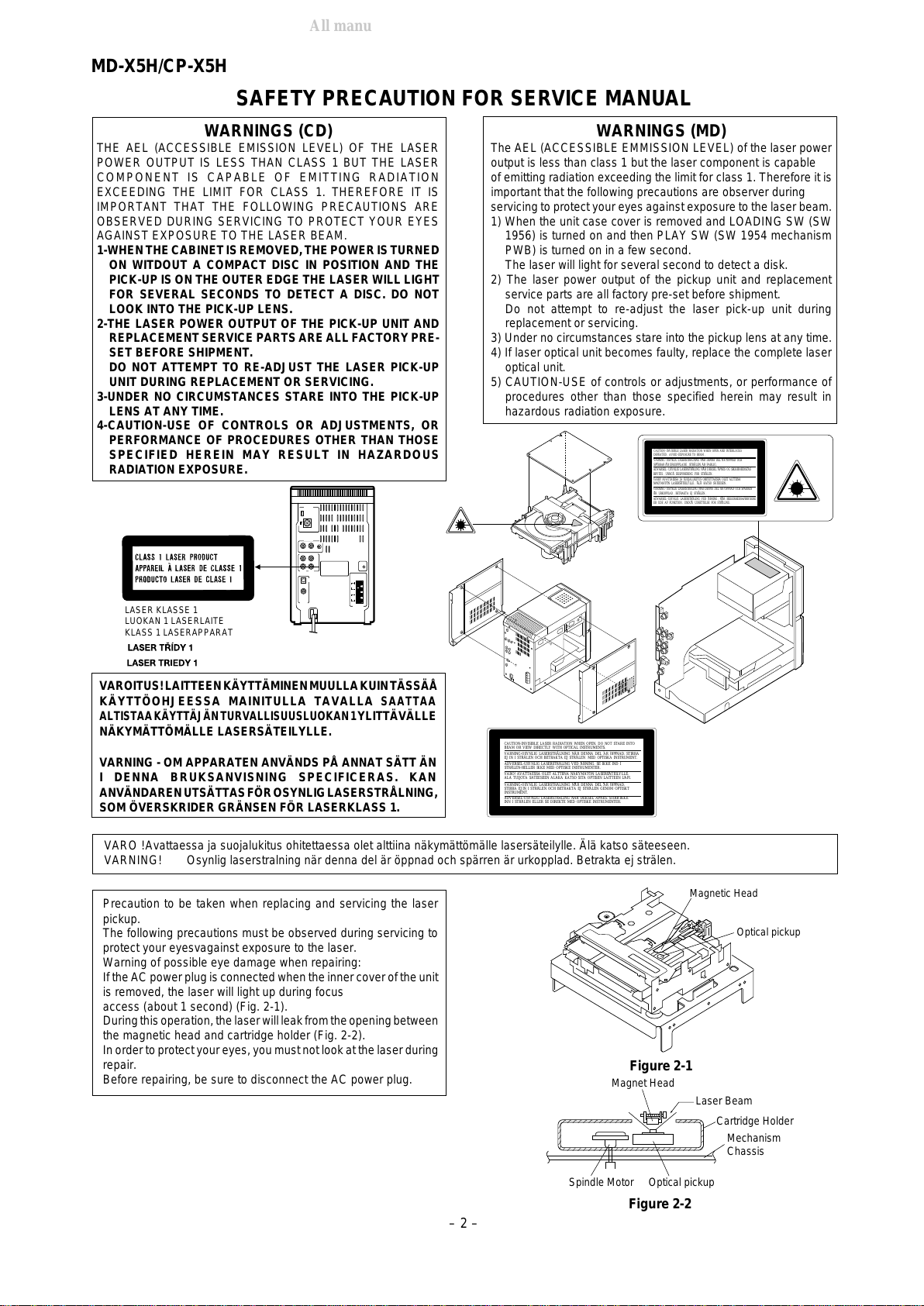
Precaution to be taken when replacing and servicing the laser
pickup.
The following precautions must be observed during servicing to
protect your eyesvagainst exposure to the laser.
Warning of possible eye damage when repairing:
Ifthe ACpowerplug is connectedwhenthe innercover ofthe unit
is removed, the laser will light up during focus
access (about 1 second) (Fig. 2-1).
Duringthisoperation,thelaserwillleakfromtheopeningbetween
the magnetic head and cartridge holder (Fig. 2-2).
Inorder toprotect youreyes, youmust notlook atthe laserduring
repair.
Before repairing, be sure to disconnect the AC power plug. Figure 2-1
Figure 2-2
Magnetic Head
Optical pickup
Optical pickup
Mechanism
Chassis
Spindle Motor
Magnet Head Laser Beam
Cartridge Holder
VAROITUS!LAITTEENKÄYTTÄMINENMUULLAKUINTÄSSÄÅ
KÄYTTÖOHJEESSA MAINITULLA TAVALLA
SAATTAA
ALTISTAAKÄYTTÄJÄNTURVALLISUUSLUOKAN1
YLITTÄVÄLLE
NÄKYMÄTTÖMÄLLE LASERSÄTEILYLLE.
VARNING - OM APPARATEN ANVÄNDS PÅ ANNAT SÄTT ÄN
I DENNA BRUKSANVISNING SPECIFICERAS. KAN
ANVÄNDARENUTSÄTTASFÖROSYNLIGLASERSTRÅLNING,
SOM ÖVERSKRIDER GRÄNSEN FÖR LASERKLASS 1.
LASER KLASSE 1
LUOKAN 1 LASERLAITE
KLASS 1 LASERAPPARAT
CAUTION-INVISIBLE LASER RADIATION WHEN OPEN. DO NOT STARE INTO
BEAM OR VIEW DIRECTLY WITH OPTICAL INSTRUMENTS.
VARNING-OSYNLIG LASERSTRALNING NAR DENNA DEL AR OPPNAD. STIRRA
EJ IN I STRALEN OCH BETRAKTA EJ STRALEN MED OPTISKA INSTRUMENT.
ADVERSEL-USYNLIG LASERSTRALING VED ABNING. SE IKKE IND I
STRALEN-HELLER IKKE MED OPTISKE INSTRUMENTER.
VARO! AVATTAESSA OLET ALTTIINA NAKYMATON LASERSATEILYLLE.
ALA TUIJOTA SATEESEEN ALAKA KATSO SITA OPTISEN LAITTEEN LAPI.
VARNING-OSYNLIG LASERSTRALNING NAR DENNA DEL AR OPPNAD.
STIRRA EJ IN I STRALEN OCH BETRAKTA EJ STRALEN GENOM OPTISKT
INSTRUMENT.
ADVERSEL-USYNLIG LASERSTRALING NAR DEKSEL APNES. STIRR IKKE
INN I STRALEN ELLER SE DIREKTE MED OPTISKE INSTRUMENTER.
CAUTION -INVISIBLE LASER RADIATION WHEN OPEN AND INTERLOCKS
DEFEATED . AVOID EXPOSURE TO BEAM .
VARNING -OSYNLIG LASERSTRALNING NAR DENNA DEL AR OPPNAD OCH
SPARRAR
AR URKOPPLADE . STRALEN AR FARLIG.
ADVARSEL - USYNLIG LASERSTRALING NAR DEKSEL APNES OG SIKKERHEDSLAS
BRYTES . UNNGA EKSPONERING FOR STRALEN .
VARO! AVATTAESSA JA SUOJALUKITUS OHITETTAESSA OLET ALTTIINA
NAKYMATON LASERSATEILYLLE . ALA KATSO SATEESEN .
VARNING - OSYNLIG LASERSTRALING NAR DENNA DEL AR OPPNAD OCH SPARREN
AR URKOPPLAD . BETRAKTA EJ STRALEN .
ADVARSEL - USYNLIG LASERSTRALING VED ABNING . NAR SIKKERHEDSAFBRYDERE
ER UDE AF FUNKTION . UNDGA UDSETTELSE FOR STRALING .
All manuals and user guides at all-guides.com

– 3 –
MD-X5H/CP-X5H
(Tuner section)
Frequency range: FM; 87.5 - 108 MHz
AM; 522 - 1,620 kHz
Sensitivity: FM; 8.0 µV (75 ohms, unbalanced)
AM; 650 µV/m
(General)
Power source: AC 230 V, 50 Hz
Power consumption: 80 W
Output power: PMPO; 80 W (total)
MPO; 40 W (20 W+20 W) DIN 45 324
RMS; 25 W(12.5 W+ 12.5 W) DIN 45 324
Input terminals: Auxilialy (Analog); 2.0 V (30 kohms)
Auxilialy (Digital-1)
Auxilialy (Digital-2)
Phono; 2.5 mV (10 kohm)
Output terminals: Headphones; 16-50 ohms
(recommended; 32 ohms)
Speakers; 6 ohms
Line out (Analog); 2.0 V (47 kohm)
Dimensions: Width; 150 mm (5-15/16")
Height; 241 mm (9-1/2")
Depth; 307 mm (12-1/8")
Weight: 4.3 kg (9.5 lbs.)
Speaker section
Type: 2-way 120 mm (4-3/4") woofer and
50 mm (2") tweeter type
Maximum input power: 25 W
Rated input power: 12.5 W
Impedance: 6 ohms
Dimensions: Width; 146 mm (5-3/4")
Height; 241 mm (9-1/2")
Depth; 229 mm (9-1/8")
Weight: 2.2 kg (4.9 lbs. )/each
Main unit section
(MiniDisc recorder section)
Type: MiniDisc recorder
Signal readout: Non-contact, 3-beam semi-conductor
laser pick-up
Audio channel: Stereo; 2 channel
Monaural; 1 channel (long-time
recording mode)
Frequency response: 20 - 20,000 Hz
Rotational speed: 400 - 900 rpm CLV, Approx.
Quantization: 16-bit linear
Filter: 8-times oversampling digital filter
Error correction: ACIRC (Advanced Cross Interleave
Reed-solomon Code)
Coding: ATRAC (Adaptive Tranceformed
Acoustic Coding)
Recording Method: Magnetic modulation overwrite method
D/A converter: 1-bit
Sampling frequency: 44.1 kHz
Wow and flutter: Unmeasurable
(less than 0.001% W. peak)
Signal/noise ratio: 95 dB (1kHz)
Dynamic range: 90 dB (1kHz)
T.H.D at 1 kHz: 0.1%
(Compact disc player)
Type: Compact disc player
Signal readout: Non-contact, 3-beam semi-conductor
laser pickup
Rotational speed: 200 - 500 rpm CLV, Approx.
Error correction: CIRC (Cross Interleave Reed-
Solomon Code)
Quantization: 16-bit linear
D/A converter: 1-bit
Filter: 4-times oversampling digital filter
Frequency response: 20 - 20,000 Hz
Signal/noise ratio: 95 dB (1 kHz)
Dynamic range: 90 dB (1 kHz)
Wow and flutter: Unmeasurable
(less than 0.001% W. peak)
SPECIFICATIONS
FOR A COMPLETE DESCRIPTION OF THE OPERATION OF THIS UNIT, PLEASE REFER
TO THE OPERATION MANUAL.
Specifications for this model are subject to change without
prior notice.
MD-X5H
CP-X5H
Beforereturning the unit to the customer after completion of a
repairoradjustmentitis necessary for the following withstand
voltage test to be applied to ensure the unit is safe for the
customer to use.
Setting of Withstanding Voltage Tester and set.
Set name set value
Withstanding Voltage Tester
Test voltage 4,240 VPEAK
3,000 VRMS
Set time 6 secs
Set current(Cutoff current) 4 mA
Unit
Judgment
OK: The “GOOD” lamp lights.
NG: The “NG” lamp lights and the buzzor sounds.
SHORT-CIRCUIT
AC POWER
SUPPLY CORD
CONNECT THE PROBE
TO GND TERMINAL
OF PHONO TERMINAL
PROBE
AC
UNIT
WITHSTANDING
VOLTAGE TESTER
+
-
OUT
OF CHASSIS
SCREW
IMPORTANT SERVICE NOTES ( FOR UK ONLY)
All manuals and user guides at all-guides.com

MD-X5H/CP-X5H
– 4 –
NAMES OF PARTS
Display window
1. Level meter/Character Information Display
2. EON Indicator: EON
3. Disc Name Indicator: DISC
4. Programme Type Indicator: PTY
5. Traffic Information Indicator: TI
6. Track Name Indicator: TRACK
7. FM Stereo Indicator: STEREO
8. Data Indicator: DATE
9. FM Stereo Indicator: ST
10. Program Indicator: PRGM
11. Random Play Indicator: RANDOM
12. Recording Level Indicator
13. Traffic Programme Indicator: TP
14. Traffic Announcement Indicator: TA
15. RDS Indicator: RDS
16. MD Pause Indicator:
17. MD Record Indicator: REC
18. Recording Level Too High Indicator
19. Repeat Indicator:
20. Sleep Indicator: SLEEP
21. More Tracks Indicator: >
22. Music Schedule Indicators
23. MD TOC Indicator: TOC
24. Recording Mode Indicator: MONO LP
25. Sound Synchro Indicator: S. SYNC
26. Clock Indicator: CLOCK
27. Remaining Time Indicator: REMAIN
28. Auto Mark Indicator: AUTO MARK
29. Total Time Indicator: TOTAL
30. Timer/Timer Record Indicator
Front panel
31. MD Slot
32. On/Stand-by Button: ON/STAND-BY
33. Recording Mode Button: REC MODE
34. CD Track Select Button: TRACK
35. CD MD Edit Button
36. Volume Up/Down Buttons:
37. .-/+ Buttons
38. Tuner Call (Band Select) Button: TUNER(BAND)
39. Auxiliary Select Button: AUX
40. Extra Bass Button: X-BASS
41. Keyboard Input Terminal
42. MD Eject Button:
43. MD Record Button: REC
44. MD Play/Pause Button:
45. MD Stop Button:
46. Remote Sensor
47. Pre-program Equalizer Button: PRE-EQ
48. CD Stop Button:
49. CD Play/Pause Button:
50. CD Open/Close Button:
51. CD Tray
52. Headphoned Jack: PHONES
53. Input Level Control: INPUT LEVEL
MD-X5H
12345 678 910 1112
13
14
15
16
17
18
19
20
21
23 24 252627 28 293022
MD/CD COMPONENT SYSTEM MD-X5
REMOTE
SENSOR
ON/STAND-BY
VOLUME
PRE-EQ
X-BASS
SAMPLING RATE CONVERTER
MD/CD/TUNER
TUNER(BAND)
PHONES
KEYBOARD
5 V ... MAX 300 mA
INPUTLEVEL
AUX
TRACK
REC MODE
CD MD
EDIT
REC
EON
31
32
33
34
35
36
37
38
39
40
41
42
43
44
45
46
47
48
49
50
51
52
53
All manuals and user guides at all-guides.com

– 5 –
MD-X5H/CP-X5H
Rear Panel
1. AM Loop Aerial Input Socket
2. FM 75 ohms Aerial Socket
3. Phono Input Sockets
4. Auxiliary Analog Input Jacks
5. Auxiliary Analog Output Jacks
6. Auxiliary Digital Input Jack (Optical)
7. Auxiliary Digital Input Jack (Coaxial)
8. AC Power Cord
9. Reset Button
10. Speaker Terminals
Speaker section
1. Tweeter
2. Woofer
3. Speaker cord
Remote Control
1. MD Track Up/Down, Cue/Review Buttons:
2. Tuner Preset CD/MDTack Number InputButtons
3. Program Button: PROGRAM
4. Clear Button: CLEAR
5. MD Record Button: REC
6. Play Mode Button: P-MODE
7. Time Display Select Button: TIME
8. Auxiliary Select Button: AUX
9. Cursor Buttons: CURSOR
10. Name/TOC Edit Button: NAME/TOC EDIT
11. Timer/Delete Button: TIMER/DELETE
12. On/Stand-by Button: ON/STAND-BY
13. Extra Bass Button: X-BASS
14. Tuning Up/Down Buttons:
15. Programme Type/Traffic Information Search Button:
PTY TI
16. EON Button: EON
17. ASPM Button: ASPM
18. FM Stereo Mode Button: ST-MODE
19. Tuner Call (Band Select) Button: TUNER/BAND
20. MD Stop Button:
21. MD Play/Pause Button:
22. Sound Synchro Button: S. SYNC
23. Recording Mode Button: REC MODE
24. Auto Mark Button: A.MARK
25. CD Play/Pause Button:
26. CD Stop Button:
27. CD Track Up/Down, Cue/Review Buttons:
28. Display Button: DISPLAY
29. Buttons
30. Message Button: MESSAGE
31. Enter Button: ENTER
32. Volume Up/Down Buttons:
33. Pre-programme Equalizer Button: PRE-EQ
MD-X5H
CP-X5H
MD-X5H
RESET
SPEAKERS
AUX ANALOG IN/OUT
AUX
DIGITAL
IN
AUX
IN
AUX
OUT
RIGHT LEFT
RIGHT
LEFT
RATED SPEAKER
IMPEDANCE ;
6 OHMS MIN.
DIGITAL1
OPTICAL
DIGITAL2
COAXIAL
AM
LOOP
FM
75 OHMS
ANTENNA
1
2
3
4
5
6
7
8
9
10
PHONO
RIGHT GND
LEFT
1
2
3
12345
678910/0
>
10
PROGRAM TUNING ST-MODE
-TUNER-
BAND
NAME
TOC EDIT
TIMER/
DELETE
CLEAR
P-MODE
REC
PTY TI EON ASPM
RDS
S.SYNC
REC MODE
A.MARK
TIME CD
-AUX-
<<
CURSOR
>>
DISPLAY
ENTER
MESSAGE
ON/STAND-BY
X-BASS PRO-EQ
VOLUME
MD
MD/CD/TUNER DIRECT KEY
MD/CD COMPONENT SYSTEM
REMOTE CONTROL
1
2
3
4
5
6
7
8
9
10
11
12
13
14
15
16
17
18
19
20
21
22
23
24
25
26
27
28
29
30
31
32
33
All manuals and user guides at all-guides.com

MD-X5H/CP-X5H
– 6 –
When you have set the date and time, this unit can be used as a clock. It
canbe usedfor timerrecordingorfortimerplayback.Itisalso usedto store
the MD recording date in memory.
1Press the ON/STAND-BY button to turn the power on.
2Press the TIMER/DELETE button.
3Within 10 seconds, press the or button to select "TIME ADJUST".
4Within 10 seconds, press the ENTER button.
The unit will enter the date setting mode.
5Adjust the day by pressing the or button.
6 Press the ENTER button to set the date.
7Adjust the month by pressing the or button.
8Press the ENTER button to set the month.
9Adjust the year by pressing the or button.
Press the button once to increase or decrease the year by one. Keep
pressing it to advance continuously.
For a year after 2000, set "00" for 2000, "01" for 2001 and so on.
10 Press the ENTER button to set the year.
The unit will enter the time setting mode.
11Adjust the hour by pressing the or button.
Press the button once to increase or decrease the hour by one. Keep
pressing it to advance continuously.
12 Press the ENTER button to set the hour.
13 Adjust the minute by pressing the or button.
Press the button once to increase or decrease the minutes by one.
When the button is held down, the time will change in increments of 5
minutes.
14 Press the ENTER button to set the minute.
The clock will start operating.
Whenabout 3secondshaveelapsed,the originaldisplay willreappear.
Notes:
In the event of a power failure or when the AC power lead is discon-
nected, the clock display will go out.
When the AC power supply is restored, the clock display will flash on
andoff toindicatethe timewhenthe powerfailureoccurred orwhenthe
AC power lead was disconnected.
Whilst recording an MD, you cannot set the date and clock. Be sure to
set the date and clock before recording.
The range of dates that can be entered is from January 1, 1997 to
December 31, 2049.
To change the setting:
Once you have set the date and time, "TIME ADJUST" will not be
displayedinstep3. Press the or buttontomakethe date and time
appear.
If you don't need to change the settings, just press the ENTER button.
To check the date and time:
Press the TIMER/DELETE button, and press the or button until the
date and time appear.
I When about 10 seconds have elapsed, the original display will reap-
pear.
SETTING THE CLOCK
2
3
4
5
6
7
8
9
10
11
12
13
14
ENTER
TIMER/
DELETE
ON/STAND-BY
PREPARATION FOR USE
Notes concerning use:
Replace the batteries if the control distance decreases or operation
becomes erratic.
Periodically clean the transmitter LED on the remote control and the
sensor on the main unit with a soft cloth.
Exposing the sensor on the main unit to strong light may interfere with
operation. Change the lighting or the direction of the unit.
Keep the remote control away from moisture, excessive heat, shock,
and vibrations.
0.2m - 6m
(8" - 20')
Remote sensor
15
15
MINIDISC SYSTEM LIMITATIONS
Even if the maximum recording time of a MiniDisc is not Whenthenumberoftracks usedreaches thelimit, regardlessof theremainder being
reached, “DISC FULL” or “TOC FULL” may be displayed. recordingtime,furtherrecordingwillbeimpossible. (Maximumnumberoftracks:255)
Even if the number of tracks and the recording time have When emphasis information (equalizer treatment in the treble section) in a track
not reached the limit, “DISC FULL” may be displayed. switches on/off many times, each change is assumed to be the beginning of a new
track, which will quickly use up all available track numbers, making further recording
impossible, regardless of the remaining time, recording time or the number of tracks
on the original.
Even if several short tracks are erased, the remaining When the remaining recording time of a disc is displayed, short tracks less than 15
recording time may not show an increase. seconds long may not be included in the total.
Two tracks may not be combined in editing. For MiniDiscs which repeated recording and editing operations were performed,
the COMBINE function may not work.
The total of the recorded time and time remaining on a disc A cluster (about 2 seconds) is normally the minimum unit of recording. So, even if a
may not add up to the maximum possible recording time. track is less than 2 seconds long, it will use about 2 seconds of space on the disc.
Therefore, the time actually available for recording may be less than the remaining
time displayed.
If there are scratches on a disc, those sections will be automatically avoided (no
recording will be placed in those sections). Therefore, recording time will be
reduced.
TROUBLESHOOTING
If a problem occurs
If this product is subjected to strong external interference (mechanical
shock, excessive static electricity, abnormal supply voltage due to light-
ning, etc.) or if it is operated incorrectly, it may malfunction or the display
may not function correctly. If such a problem occurs, do the following:
1Unplug the AC power lead from the AC socket.
2Press the RESET button on the back of the unit for at least 3 seconds.
3Plug the AC power lead back into the AC socket.
Whenthe RESETbutton ispressed,allofthesettingsinmemorywillbe
erased.
If strange sounds, smells or smoke come out of the unit, or if a foreign
object falls into the unit, turn off the power, unplug the AC power lead
from the AC socket immediately. Contact the shop where you pur-
chased the unit.
RESET
OPERATION MANUAL
All manuals and user guides at all-guides.com
all-guides.com

– 7 –
MD-X5H/CP-X5H
(Continued)
When an error message is displayed, proceed as follows:
Error messages Meaning Remedy
BLANK MD • Nothing is recorded. • Replace the disc with a recorded disc.
(
Neither music nor a disc name have been recorded on this MD
.)
Can't COPY •
You tried to record from a disc which you are not allowed to copy.
•
Replaceitwithanotherdiscwhich you can copyfrom(regularCD)
.
Can't EDIT • A track cannot be edited. •
Change the stop position of the track and then try editing it.
Can't REC • Recording cannot be performed correctly due to vibration • Rerecord or replace it.
or shock in the unit.
DEFECT • Since this disc has scratches on it, the recording operation • Replace the disc with another recordable disc.
was skipped.
Din UNLOCK • Incorrect digital signals are input. • Connect correct digital signals.
• Use analogue inputs.
DISC ERR* • The disc is damaged or there is no TOC on the disc. • Reload the disc or replace it.
DISC FULL • The disc is out of recording space. •
Replace the disc with another recordable disc.
EDIT OVER • There is no space left for recording CD. • Replace it with another recordable disc.
FOCUS ERROR • The proper focus cannot be obtained. • Reload the disc.
MD ERROR • The unit has determined that it is out of order •Askthe store whereyou purchasedthis unit,about repairs.
by performing a self-diagnosis.
MECHA ERR* • There is a mechanical problem and the disc is not working • Turn off the power, and press the button.
properly.
NAME FULL • The number of characters for the disc name or track name • Shorten the disc or track name.
exceeds 100.
NO DISC • A disc has not been loaded. • Load a disc.
• The disc data cannot be read. • Reload the disc.
NOT AUDIO • The data recorded on this disc is not audio data. • Select another track.
• Replace the disc.
PLAYBACK MD • You tried to record on a playback-only disc. • Replace it with a recordable disc.
PROTECT • The unit has determined that it is out of order by performing a •
Turnthepower off andbackon.Ifthe problem isnot resolved,
self-diagnosis.
ask the store where you purchased this unit, about repairs.
PROTECTED • The disc is write protected. • Move the write protection tab back to its original position.
TEMP OVER • The temperature is too high. • Turn off the power, and wait for a while.
TOC ERR* • The disc has a large amount of damage. • Replace the disc with another disc.
• TOC information cannot be read.
• The MD does not meet the specifications for MDs.
TOC FULL* • There is no space left for recording character information • Replace it with another recordable disc.
(track names, disc names, etc.).
TOC W ERROR • The unit has determined that it is abnormal •Ask the store whereyoupurchasedthisunit, about repairs.
by performing a self-diagnosis.
U TOC ERR* • The TOC information on this disc does not meet the MD • Replace it with another disc.
specifications or it cannot be read. • Erase all the data, and try recording.
U TOC W ERROR • The TOC information could not be created properly due to • Turn off the power, and try to write the TOC again.
a mechanical shock or to scratches on the disc. (Remove any source of shock or vibration whilst writing.)
? DISC • The data contains an error. • Replace the disc with another disc.
0 00:00 • Music is not recorded. • Replace the disc with a recorded disc.
*: Number or symbol
All manuals and user guides at all-guides.com

MD-X5H/CP-X5H
– 8 –
Caution on Disassembly
Whe disassembling the machine or assenbling it after
repair, observe the following instructions so as to ensure
safety and keep its performance.
1. Unload the compact disc, and mini-disc from machine.
2. Be sure to unplug the power cable before starting
disasembly of the machine.
3. When disassenbling each section, remove the nylon
band or wire arrangement.
If a screw of improper length is fit to the MD mechanism.
(a screw fit the part to the mechanism chassis of MD
section), it may cantact the optical pickup, impeding
normal operation. Hence, due care must be taken.
4. While repairing, pay utmost attention to static electricity
on ICs.
1 Top Cabinet 1. Screw ................ (A1) x4 8-1
2 Side Panel 1. Screw ................ (B1) x10 8-1
(Left/Right)
3 Rear Panel 1. Screw ................ (C1) x6 8-1
2. Socket ............... (C2) x1 8-2
4 Power Amp. PWB 1. Screw ................ (D1) x2 8-2
2. Socket ............... (D2) x4
5 Main PWB 1. Screw ................ (E1) x2 8-2
2. Socket ............... (E2) x4 8-3
3. Flat Wire............ (E3) x1
6 MD Holder 1. Screw ................ (F1) x4 8-3
(MD Unit) 2. Socket ............... (F2) x1
3. Flat Cable.......... (F3) x1
7 Power Supply PWB 1. Screw ................ (G1) x4 8-3
8 CD Holder 1. Screw ................ (H1) x4 9-1
(CD Mechanism/ 2. Socket ............... (H2) x1
CD Servo PWB) 3. Flat Wire............ (H3) x1
9 Front Panel 1. Screw ................ (J1) x2 9-1
10 Display PWB 1. Screw ................ (K1) x10 9-1
11 Jack PWB 1. Screw ................ (L1) x2 9-2
12 CD Servo PWB 1. Screw ................ (M1) x3 9-3
(Note 1)
13 CD Mechanism 1. Screw ................ (N1) x3 9-4
14 MD Mecha Unit 1. Screw ................ (P1) x7 9-5
15 MD Main PWB 1. Screw ................ (Q1) x4 9-6
2. Socket ............... (Q2) x6
16 MD Mechanism 1. Screw ................ (R1) x4 10-1
DISASSEMBLY
Figure 8-2
Figure 8-3
STEP REMOVAL PROCEDURE FIGURE
Figure 8-1
MD-X5H
STEP REMOVAL PROCEDURE FIGURE
1 Front Panel 1. Net........................... (A1) x2 10-2~5
3. Screw ...................... (A2) x6
2 Speaker 1. Screw ...................... (B1) x4 10-6
3 Tweeter 1. Screw ...................... (C1) x2 10-6
CP-X5H
MD-X5H
(F1)x2
ø2.6x10mm
(F1)x2
ø2.6x10mm
(G1)x4
ø4x10mm
Power Supply PWB
MD Holder
MD Mecha Unit
(D2)x1 (F2)x1
(F3)x1
Note1: After disconnecting theoptical pickup connector wrap
the front end of connector in the conductive aluminium foil so
as to prevent electrostatic damage of optical pickup.
(A1)x1
ø3x10mm
(A1)x2
ø3x10mm (A1)x1
ø3x10mm
(B1)x1
ø3x10mm
(B1)x1
ø3x10mm
(B1)x1
ø3x10mm
(B1)x2
ø3x10mm
(B1)x2
ø3x10mm
(B1)x2
ø3x10mm
(C1)x6
ø3x8mm
(B1)x2
ø3x10mm
Top Cabinet
Side Panel
(Left)
Side Panel
(Right)
Rear Panel
Pull
Pull
(D1)x1
ø3x10mm
(E1)x1
ø3x10mm
(E1)x1
ø3x10mm
(E2)x1
(D2)x1
(E2)x1
(E3)x1
(D2)x1
(D2)x1 (D1)x1
ø3x10mm
Power Amp. PWB
(E2)x2
Main PWB
(C2)x1
All manuals and user guides at all-guides.com

– 9 –
MD-X5H/CP-X5H
Figure 9-2
Figure 9-3
Figure 9-1
Jack PWB
(L1)x2
ø2.6x10mm
Front Panel
CD Servo PWB
(M1)x3
ø2.6x10mm
Figure 9-5
Figure 9-6
Figure 9-4
CD Mechanism
(N1)x3
ø2.6x10mm
Shield Case (Top Sode)
Shield Case
(Bottom Side)
(P1) x 1
ø2 x 4mm
(P 1) x 1
ø3 x 10mm
(P1) x 1
ø2 x 4mm
(P1) x2
ø3 x 10mm
MDMecha Unit
(P1) x 1
ø2 x 4mm
(P1) x 1
ø2 x 4mm
MD Main PWB
(Q2)x1
Pull
Pickup Flexible
PWB (*1)
Frame
( Q2 ) x 1
( Q2 ) x 3
( Q2 ) x 1
( Q1 ) x 4
ø1.7 x 3mm
(*1) After disconnecting the optical
pickup flex PWB from the
connector wrap the front end of
flex PWB in conductive aluminium
foil so as to prevent electrostatic
damage of optical pickup.
(H1)x4
ø3x10mm
(J1)x2
ø3x6mm
(H2)x1
(H3)x1
(K1)x10
ø2.6x10mm
Front Panel
CD Holder
Display PWB
All manuals and user guides at all-guides.com

MD-X5H/CP-X5H
– 10 –
CP-X5H
Figure 10-2
Figure 10-3
Figure 10-1
Figure 10-5
Figure 10-6
Figure 10-4
(R1)x4
ø1.7x8.9mm
MD Mechanism
Front Pane
(A2)x2
ø4x16mm
(A2)x4
ø4x16mm
(A1)x2
(B1)x4
ø4x16mm
(C1)x2
ø4x16mm
Speaker
Tweeter
Bottom Side
Insert the head of screwdriver
or metallic bar (2.5 or less) into
the panel notch hole.
1
Insert the head of screwdriver into the hole,
and push further the screwdriver, pulling up
the net. Thereby the lower pawl is disengaged
It is better to hold the
screwdriver aslant as
shown in the figure.
2
1
1
2
3
After disengaging the lower pawl pull slightly
in the arrow direction 1 , and then pull in the
direction 2 . Thereby the net can be removed.
Push the vicinity of end
of center decoration notch.
4
5
Insert the head of screwdriver near
4
, push further the
screwdriver, pulling up the net. Thereby the lower pawl is
disengaged(atfirstdisengageatonesideandthenatother
side).
6
After disengaging bothpawls disengage the upper pawl by
the same procedure as stated in
3
above.
All manuals and user guides at all-guides.com

– 11 –
MD-X5H/CP-X5H
REMOVING AND REINSTALLING THE MAIN PARTS
MD MECHANISM SECTION
Performsteps1to3ofthedisassemblymethodtoremovethe
MD mechanism.
How to remove the magnetic head
(See Fig. 11-1)
1. Remove the screws (A1) x 1 pc.
Caution:
Takeutmostcaresothatthemagneticheadisnotdamaged
when it is mounted.
How to remove the cartridge holder
(See Fig. 11-2)
1. Open the rpller arm lever in the arrow direction, and lower
the clamper lever to the rear side.
2. Apply +5V to the red line side of blue connector of loading
motor,push therackgearinthearrowdirectiontomove the
cam plate lever until tick is heard.
3. Remove the screw (B1) x1 pc., and the spring (B2) x1 pc.,
fitted to the holder arm, and shift the cartridge holder to the
left side to remove it.
How to remove the mechanism switch PWB
(See Fig. 11-3)
1.Removethescrews(C1)x2pcs.,andremovethemechanism
switch PWB.
Figure 11-1
Figure 11-2
Figure 11-3
MD Mechanism
(A1)x1
ø1.7x5mm
Magnetic Head
Slider Lever
Cartridge Holder
Clampa Lever
Lack Gear
Roller Arm Lever
Loading Motor
Cam Plate Lever
(B1) x1
Ø1.7x5mm
(B2) x1
(C1)x1
Ø1.7x3mm
(C1)x1
Ø1.7x9.5mm
MD Mechanism
Switch PWB
All manuals and user guides at all-guides.com
all-guides.com

MD-X5H/CP-X5H
– 12 –
How to remove the sled motor/loading motor
(See Fig. 12-1)
1. Remove the screws (D1) x 1 pcs., and remove the sled
motor/loading motor.
Caution:
Be careful so that the gear is not damaged.
(The damaged gear emits noise during searching.)
Figure 12-1
Figure 12-2
Figure 12-3
How to remove the spindle motor
(See Fig. 12-2)
1. Remove the screws (E1) x 3 pcs., and remove the spidle
motor.
Caution:
Be careful so that the turntable is not damaged.
How to remove the optical pickup
(See Fig. 12-3)
1. Remove the screws (F1) x 3 pcs.
Caution:
Be careful so that the gear is not damaged.
(The damaged gear emits noise during searching.)
Sled Motor
Loading
Motor
(D1)x2
Ø1.7x2mm (D1)x2
Ø1.7x2mm
Spindle Motor
Turntable
(E1)x3
Ø1.7x2.5mm
Optical Pickup
(F1)x3
Ø1.7x9.5mm
All manuals and user guides at all-guides.com

– 13 –
MD-X5H/CP-X5H
Figure 13-1
How to remove the pickup (See Fig. 13-1)
1. Remove the screw (A1) x 2 pcs., to remove the shaft (A2)
x 1 pc.
2. Remove the stop washer (A3) x 1 pc., to remove the gear
(A4) x1 pc.
3. Remove the pickup.
Note:
After disconnecting the optical pickup connector wrap the
front end of connector in the conductive aluminium foil so as
to prevent electrostatic damage of optical pickup.
CD MECHANISM SECTION
Perform steps 1,to 7 and 12 of the disassembly method to
remove the CD mechanism.
How to remove the CD loading motor
(See Fig. 13-2)
1. Remove the belt (B1) x 1 pc.
2. Remove the screw (B2) x 2 pcs.
3. Remove the loading motor.
Note:
After disconnecting the optical pickup connector wrap the
front end of connector in the conductive aluminium foil so as
to prevent electrostatic damage of optical pickup.
Figure 13-2
( A1 ) x2
2.6 x 6 mm
Stop Wassher
( A3 ) x1
CD Mechanism
Gear
( A4 ) x1
Shaft
( A2 ) x1
Optical Pickup
(B2) x 2
Ø 2 x 4mm
CD Unit
Belt
(B1) x 1 Loading Motor
All manuals and user guides at all-guides.com

MD-X5H/CP-X5H
– 14 –
ADJUSTMENT
fL: Low-range frequency
fH: High-renge frequency
• AM IF/RF
Figure 14-1 AM IF
TUNER SECTION • Setting the Test Mode
HoldingdownthePRE-EQbuttonandTUNER(BAND)button,
pressthe POWER button. Frequency is set in the memory as
shown in Table 19. Call it with the PRESET button for tuner
circuit adjustment and check.
Preset No. Frequency
P01 87.5 MHz P06 522 kHz
P02 108.0 MHz P07 1,620 kHz
P03 90.0 MHz P08 603 kHz
P04 106.0 MHz P09 1,404 kHz
P05 98.0 MHz P10 990 kHz
Figure 14-3 ADJUSTMENT POINTS
Adjusting item Adjusting object Adjusting
method
IF T351 Indication of IF waveform 450
set must be 1,620 kHz. kHz is set to max.
Frequency cover fL: T302 (522 kHz) fL: 1.1 ±0.1 V
(Voltage of Pin 20 Set Diplay of 522 kHz. fH: 5.1 ±1.3 V of
IC302 VT line) (Only check)
Tracking fL: T302 (990 kHz) Set output of
speaker terminal
to maximum.
AM Signal oscillator Frequency 400 Hz, 30% modulation
• FM Mute Level
Adjusting
method Adjusting
object
Adjusting
method
98.0 MHz 98.0 MHz VR351 Input: SO301
(30 dB) Output: Speaker
Terminal
FM Signal oscillator Frequency 400 Hz, 22.5 kHz
Adjusting object
Preset No. Frequency
Figure 14-2 FM Mute Level
Electric
Voltmeter
GND
AM Loop Antenna
AM signal oscillator
Loop Antenna
UNIT
IF: Speaker Terminal
Frequency cover: IC302 Pin20
Electric
Voltmeter
UNIT
FM signal oscillator SO301 Speaker
terminal
20
112
13
VR351T351AM IF
T302
FM MUTE
LEVEL
FE301
IC302
AM
TRACKING fL AM BAND
COVERAGE fL
MAIN PWB
ANTENNA
TERMINAL
All manuals and user guides at all-guides.com

– 15 –
MD-X5H/CP-X5H
CD TEST MODE
CD test mode setting
Any TEST mode can be set as shown below by pressing several buttons.
Holding down TACK UP/CUE and CD PLAY/PAUSE, turn on POWER.
Test Mode
Function - CD TEST mode
Test mode setting
CD TEST mode indication
Open/Close operation is button.
The pickup can be moved with the ( ) or ( ) button.
<TRACK>
On-spot tracking
Servo OFF playback
<CD>MD EDIT>
On-spot tracking
Servo ON playback
<PLAY> button input - TOC. Initialization is executed, and normal PLAY is executed.
Press the <STOP> button. Stop
If the following button is pressed during PLAY, any track No. can be specified directly.
<TUNER (BAND)> button: Track 4
<AUX> button: Track 9
<X-BASS> button: Track 15
Note:
The pickup can be moved with the ( ) or ( ) button only in STOP state.
Cancel method: POWER OFF
Initialization is not executed.
CD section
The CD system has the following automatic adjusting function. Therefore readjustment is not required when the pickup is
replaced. Since adjustment of this CD unit is not required, the combination of PWB and laser pickup unit is not restricted.
Automatic adjustment items
1. Focus Offset (Fig. 15-1)
2. Tracking Offset (Fig. 15-2)
3. E/F Balance (Tracking Error Balance) (Fig. 15-3)
4. R/F level AGC function (HF level: Constant)
5. Tracking gain RF level automatic follow-up
This adjustment is executed whenever the disc is
changed. Therefore the optimum setting is used for
playback of each disc.
Figure 15-1
Figure 15-2 Figure 15-3
2
0.1s
0.50 V
IC1 20 FE
0.1s
0.50 V
IC1 7 TE
1
Focus Offset
Adjustment
Tracking Offset
Adjustment
2
1
10ms
0.50 V
IC1 20 FE
10ms
0.50 V
IC1 7 TE Tracking
Offset
Adjustment
2
1
TO
TE
200 ms
1V/diV
IC 1 15
200 ms
1V/diV
IC 1 7
Tracking/
Error Balance
Adjustment
All manuals and user guides at all-guides.com

MD-X5H/CP-X5H
– 16 –
RDS
1. RDS Function
PI ASPM
PS STATION NAME
PTY PTY SEARCH
PTY(31)
EON TI (TA) STAND-BY MODE
EON-PTY EON-TI/PTY
EON-AF With EON-AF
TP ind.
TA ind.
2. DISPLAY and control buttons
Select and search (18 kind items) by cyclic
NEWS-AFFAIRS ------ OTHER M - ALARM - TP - TA
Select and stand-by (17 kind items) by cyclic
NEWS-AFFAIRS ------ OTHER M - ALARM - TI
Note:
TP and TA ind. are different from CD-C75H.
TP, TA ind. can light up individually, when TP:OFF and TA: ON, it means that EON-TI can be used, in case of TP=OFF, TA=OFF,
EON-Ti can't be used.
In case of CD-C75H, (TP: OFF and TA: ON) disregard (ignore) this case, because EON-TI is nothing.
AF: Alternative Frequencycies
RDS Function
DISPLAY and control buttos
AF: Alternative Frequencycies
Information Provided by RDS
WiththeMD-X5H,you can watch twotypesofRDSservice. To show them
on the display, press the DISPLAY button.
Each time you press the DISPLAY button, the display will change to show
the following information.
Level meter
Stationnamescommonly known
willbedisplayed."PS: "appears
if no signal is being sent.
Programme type will be dis-
played.
"PTY: " appears if no signal is
being sent.
Station name you assigned.
(Preset station)
PS (Programme Service):
PTY (Programme Type):
Station name:
Level meter:
Descriptions of the PTY (Programme Type) codes, TP (Traffic Programme) and TA (Traffic Announcement)
With the MD-X5H, you can search for and receive the following PTY, TP and TA signals.
News: News
Affairs: Topicalprogrammeexpandingonthecurrentnews
or affairs
Info: Programmes on medical service, weather fore-
cast, etc.
Sport: Sports events
Educate: Educational programmes
Drama: Radio plays
Culture: Programmes on national or regional culture
Science: Programmesonnationalsciencesandtechnology
Varied: Other programmes like comedies or ceremonies
Pop M: Pop music
Rock M: Rock music
M.o.R. M: Middle-of-the-road music (usually called "easy listen-
ing")
Light M: Light music
Classics: Classics
Other M: Other music
Alarm: Emergency broadcasts
NONE: No programme type (receive only)
TP: Broadcasts which carry traffic announcements
TA: Trafficannouncementsarebeingbroadcastatpresent.
Note:
When the unit is in the EON stand-by mode and a programme is
selected, the unit will display "TI" instead of "TP" or "TA".
DISPLAY
ASPM
PTY TI
ENTER
EON
All manuals and user guides at all-guides.com
all-guides.com

– 17 –
MD-X5H/CP-X5H
No
ASPM, summary operation
Hold down the ASPM button for 3 more second.
“ASPM” blinks in the display.
Preset CH memory full over? No operate.After displayed “0 MEMORY END”.
Return to previous station.
SD (TUNE) DET out OK?
If count 1st OK?
If count 2nd OK?
RDS signal or not? PI—identify
Comparing PI cord same or not?
between current receiving PI and
before PI which is already memorized
by ASPM on this time.
Comparing freg. same or not?
between current receiving frequency
and (already) previously memorized
frequency.
Memorized to the lowest
vacant preset channel.
Preset CH memory become full over?
Begin to ASPM SCAN from the next
CH-SPAN again.
Repeat and continue with same format
ASPM operation untill 108 MHz.
After reached 108 MHz, displayed the
TTL quantity of memorized stations.
And return to the previous receiving
freq. automatically.
Displayed the TTL quantity of memo-
rized stations by ASPM operation on
this time.And return to the previous
receiving freq. automatically.
Yes
No
Yes
Yes
Yes
Yes
No
No
No
No
No No Effect
Pass
No effect
Pass
No effect
Pass
No effect
Pass
No effect
Yes
No
Yes
Compare the field strength of current
receiving signal. Is receiving signal
stronger than signal which has same PI
cord and is already memorized to
preset memory ahead of this receiving
time?
Yes No effect
No No effect
Comparing freg. same or not?
Between current receiving frequency
and (already) previously memorized
frequency.
Yes Memorized to the lowest
vacant preset channel.
Yes No effect
Begin to scan start 87.50 → 108.00 MHz
All manuals and user guides at all-guides.com

MD-X5H/CP-X5H
– 18 –
4. No adjust type (None adjusting circuit.)
5.Added EON button.
6.Need to change RDS logo due to add EON feature.
7. Added EON—TI, EON—PTY function.
3. Summary of MD-X5H RDS—EON operation
EON—PTY: Select and set the desired “PTY” → stand-by → switch to ON(other network) Station at the start of desired
PTY automatically → stay and listen to PTY of ON station → switch back to TN(This net) station automati
cally at the end of PTY(ON) i.e.after changing to another PTY(except AFFAIRS) or cancelling to receive
PTY of ON station midway.
EON—TI: Select and set the “TI” → stand-by → switch to ON station at the start of traffic announcement automati
cally → stay and listen to TA of ON station → switch back toTN station autmatically at the end of TA(ON).
ie after TA(ON) is over or cancelled to receive TA of ON station midway.
When switching TN → ON station.
In case of exist 2 more stations having the desired(specified) “PTY” or “TI”, the receiver will select and
switch to ON station comparing field strength at the same time.But when the frequency of ON station
exists in the preset-memory, then reciver switches straight to that ON station(CH), without comparing field
strength so can make a quick switching from TN—ON station.Preset memory takes priority of switching
TN—ON station.
therefore ASPM is usefull not only for PTY search but also for rapid EON switching. Anyway MD-X5H’s
EON is basically stand-by and receiving method, along with the Guidelines for EON implementation.
• ASPM SCAN: 87.50MHz →108.00 MHz.
• Only RDS signal is memorized by ASPM because RDS signal has PI code and is suitable and convenient for ASPM operation.
ASPM
Comparing field strength, only one strongest RDS station is memorized of all stations (repeater relay stations) that have same
PI code.
Same PI code — freq: different
(AF’S)
PS: same
PTY: same
Each PI has AF’S list by individually.
Exa: P1 has f1, f2, f3(same PTY).
P2 has f4, f5(same PTY).
[For example] Pickup and memorized to preset CH.
f 1
f 2 f 3
P 1 (PI cord)
PS 1 (Station Name)
f 5 f 4
P 2
PS 2
f 6
f 7 f 8
P 3
PS 3
f 9 f 10
f 11 f 12 f13
P 4
PS 4
Select signals (f1, f5, f7, f10) are memorized in the preset memory by ASPM.
• If tentative - ASPM operation is repeated intententionally, never memorized (over write) at the same frequecy.
1st time ASPM → strongest stations of each pi are memorized.
ASPM is not only very usefull for PTY search, but also EON operation.
2nd time ASPM →2nd strong stations of each pi are memorized and so on.
PTY search function is equal to FM band search function as a result.
1. Introduction of RDS for MD-X5H
MD-X5H RDS function is equal to adding EON feature to the current CD-C75H RDS.
EON feature is EON—PTY and EON—TI.
Although PTY and TI indicators are separated, PTY contains TI in the PTY items (software) like current PTY search items.
NEWS, AFFAIRS, INFO, ALARM, TI (TTL 17 kinds)
EON—PTY EON—TI
Can select and stand-by Can select and stand-by
EON—PTY and EON—TI are basically stand-by →receive the desired program of ON station.
2.The difference point from current CD-C75H RDS. (CD-C75H — MD-X5H)
1. PTY item: added TA.TTL 18 kind.
2. Each “TP”, “TA” ind.light up or go out individually.
“TA” ind.doesn’t light up on current model, CD-C75H due to none EON—TI.
3. Added 3 indicators(in FL) due to adding EON feature.
EON: Lights up only during receiving EON data (14A).
TI: During EON-TI stand-by →Light up
During receiving ON station.→blink.
PTY: During EON-PTY stanb-by →Light up
During receiving ON station.→blink.
---
---
↑↑
All manuals and user guides at all-guides.com

– 19 –
MD-X5H/CP-X5H
EON summary notice for reference
1. EON-TI/PTY EON stand-by can be set, only when EON ind. lights up.
While EON ind. goes out (NO EON STATION), EON stand-by can't be set.
If the EON button is pressed, then “NO EON” is indication the display.
2. EON-TI/PTY Even if switch back ON→TN station continue to keep EON stand-by.
3. EON-TI Don’t switch TN→ON during TN broadcast TA. (same item)
4. EON-TI/PTY
EON can be cancelled during receiving ON station by pressing EON button if necessary and
switch back ON
→
TN.
5. EON-TI/PTY EON stand-by is perfectly cancelled (cleared) by pressing EON button 2 times during stand-by or
powerOFF or Tun Up/Down or change band or recall pre-set CH.
6. EON-TI/PTY After setting EON stand-by, stand-by items can be confirmed by pressing EON button one time.
7. EON-TI/PTY EON button function: • EON setting
• Confirm stand-by items
• Cancel (ON→TN)
• EON clear cancel (2 times)
8. EON-TI/PTY After setting EON-TI and EON-PTY stand-by, if when EON data is not transmitted, EON ind goes out
and EON stand-by is automatically cancelled display “NO EON”.
9. EON-TI EON-TI stand-by can't be set. When TP=0,TA=0(TN) even if EON ind. lights up and the EON button is
pressed then “NO TI” is indication the display.
10. EON-PTY Don’t switch TN→ON during TN broadcast same specified PTY. (same item of PTY)
11. EON-TI/PTY Switch TN→ON→TN station one cycle.
Never switch TN→ON1→ON2→Other net to other net station.
12. EON-TI/PTY After switch TN→ON station. When ON station is NO RDS, NO signal, TA=OFF or different PTY items.
The receiver switch back ON→TN displaying “NO READY”.
13. During receive ON station. when ON station become to be NO RDS, NO signal, TA=ON to OFF or
different PTY item, The receiver switch back ON→TN.
14. EON-TI/PTY Switch TN→ON in case of 2 more stations exist, comparing field strength and switch to thestrongest
station, if these signals are same strength, switch to the first previous station.
If same frequency as AF'Sexists in the preset memory, then switch TN→ON (preset memory station)
straight.
In case of exist 2 more preset memories of AF’S,then switch to the preset CH which taken in EON DATA
first, also in this case no concern to field strength.
15. Even if switch TN→ON preset memory straight, that ON station is very weak signal, then search another
AF'S (ON) station comparing field strength and switch to the strongest station as a result. Of all atations
of AF'S are very weak or no good condition, then, switch back ON→TN automatically display "NO
READY".
16. EON-TI/PTY No linkage volume, power ON/OFF, and switch function.
Traffic Programme code
(TP) Traffic Announcement code
(TA) Applications
OFF OFF This programme does not carry traffic announcements nor does
it refer, via EON, to a programme that does.
OFF ON This programme carries EON information about another
programme which gives traffic information.
ON OFF This programme carries traffic announcements but none are
being broadcast at present and may also carry EON information
about other traffic announcements.
ON ON A traffic announcement is being broadcast on this programme at
present.
All manuals and user guides at all-guides.com

MD-X5H/CP-X5H
– 20 –
1. Preparation for adjustment
Test disc
MD SECTION
Type Test disc Part No.
1 High reflection disc TGYS1 (SONY) RRCDT0101AFZZ
2 Low reflection disc Recording minidisc UDSKM0001AFZZ
3 Head Adjusting transparent RRCDT0103AFZZ
Extension Cable (See Fig. 30-4)
Type Part No.
1 Extension PWB for servicing RUNTK0457AFZZ
2 Extension Connector (2 Pin) QCNWK0059AFZZ
3 Extension Connector (6 Pin) QCNWK0107AFZZ
4 Extension Cable (5 Pin) QCNWK0109AFZZ
3 Extension Cable (28 Pin) QCNWK0108AFZZ
2. Test mode
Test mode setting method
1. Holding down the + button and MD (PLAY/PAUSE) button, press the POWER button.
(State A is changed to state B .)
2. Insert the playback disc 1 (high reflection disc) or recording disc 2 (low reflection disc). (State C is set.)
Thus, the test mode state is set.
A tsm e : TEST MODE represents version of MD microcomputer.
TEST STOP state (When the MD (STOP) button is ressed in the C state, the indication A
is restored. To restore C again, press the CD (PLAY/ PAUSE)
button.)
B EJECT
TEST
C AUT YOBI
TEST
Entering the specific mode
Whenever the CD (PLAY/PAUSE) button is pressed, the mode is changed.
AUTO pre-adjustment AUTO adjustment RESULT Pre-adjustment
EEPROM setting MANUAL adjustment MANUAL pre-adjustment RESULT MANUAL pre-adjustment
• Canceling the test mode
When the POWER button is pressed, the test mode is canceled, and the POWER OFF state is set.
• Note
Remove the MD unit for repeir, and after installing it in the set, be dure to reset it and ascertain that reset has been done.
Resetting procedure (1) Unplug the AC cord from the socket, and hold down the RESET buttonm provided at the rear side
for more than 10 seconds.
(2) Once set the TEST MODE (holding down the TEST MODE (X-BASS botton) and botton
together, press the POWER button), and then turn off power.
All manuals and user guides at all-guides.com
Other manuals for MD-X5H
1
This manual suits for next models
1
Table of contents
Other Sharp Stereo System manuals

Sharp
Sharp MD-M1 User manual

Sharp
Sharp XL-UH4H User manual

Sharp
Sharp XL-DH259P User manual

Sharp
Sharp CD-C500Z User manual

Sharp
Sharp GBOXS0072AWM1 User manual

Sharp
Sharp CD-DVD500H User manual

Sharp
Sharp XL-60H User manual

Sharp
Sharp CD-ES111H User manual

Sharp
Sharp CD-MPX100H User manual

Sharp
Sharp CD-C602 User manual

Sharp
Sharp CD-DP900H User manual

Sharp
Sharp XL-MP2H User manual

Sharp
Sharp XL-ES5 User manual

Sharp
Sharp XL-MP130 User manual

Sharp
Sharp MD-E9000H User manual

Sharp
Sharp CD-MPS600W User manual

Sharp
Sharp CD-ES111H User manual

Sharp
Sharp XL-DH320NH User manual

Sharp
Sharp XL-UR27H User manual

Sharp
Sharp HT-SBW260 User manual