Sharp MD-X60 User manual

– 1 –
MD-X60
CONTENTS
MD-X60
SERVICE MANUAL
SHARP CORPORATION
No.S6839MDX60///
• In the interests of user-safety the set should be restored to its original
condition and only parts identical to those specified should be used.
This document has been published to be used
for after sales service only.
The contents are subject to change without notice.
Page
IMPOTANT SERVICE NOTES .......................................................................................................................................... 2
SPECIFICATIONS ............................................................................................................................................................. 2
NAMES OF PARTS ........................................................................................................................................................... 3
OPERATION MANUAL ...................................................................................................................................................... 6
QUICK GUIDE ................................................................................................................................................................... 8
DISASSEMBLY.................................................................................................................................................................. 9
REMOVING AND REINSTALLING THE MAIN PARTS................................................................................................... 13
ADJUSTMENT ................................................................................................................................................................. 16
WIRING DIAGRAM .......................................................................................................................................................... 30
BLOCK DIAGRAM ........................................................................................................................................................... 32
SCHEMATIC DIAGRAM / WIRING SIDE OF P.W.BOARD............................................................................................. 36
NOTES ON SCHEMATIC DIAGRAM .............................................................................................................................. 62
TYPE OF TRANSISTOR AND LED ................................................................................................................................. 62
WAVEFORMS OF CD CIRCUIT...................................................................................................................................... 63
WAVEFORMS OF MD CIRCUIT ..................................................................................................................................... 64
TROUBLESHOOTING (CD SECTION) ........................................................................................................................... 66
TROUBLESHOOTING (MD SECTION) ........................................................................................................................... 70
FUNCTION TABLE OF IC................................................................................................................................................ 75
REPLACEMENT PARTS LIST/EXPLODED VIEW/PACKING OF THE SET
Dolby noise reduction manufactured under license from Dolby
Laboratories Licensing Corporation.
"DOLBY" and the double-D symbol are trademarks of Dolby
Laboratories Licensing Corporation.
It is the intent of Sharp that this product be used in full compliance
withthecopyrightlawsoftheUnitedStatesandthatpriorpermission
be obtined from copyright owners whenever necessary.
US and foreign patents licensed from Dolby Laboratories Licensing
Corporation.

MD-X60
– 2 –
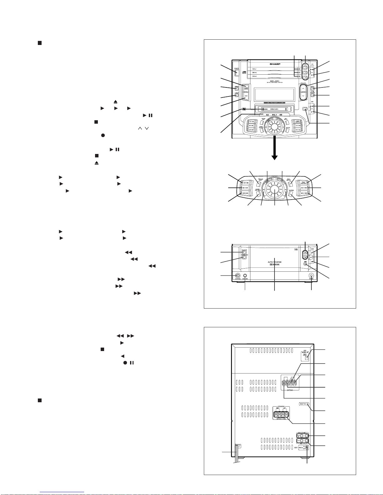
FOR A COMPLETE DESCRIPTION OF THE OPERATION OF THIS UNIT, PLEASE REFER
TO THE OPERATION MANUAL.
IMPORTANT SERVICE NOTES
BEFORE RETURNING THE AUDIO PRODUCT
(Fire & Shock Hazard)
Before returning the audio product to the user, perform the following
safety checks.
1. Inspect all lead dress to make certain that leads are not pinched
or that hardware is not lodged between the chassis and other
metal parts in the audio product.
2.Inspectallprotectivedevicessuchasinsulatingmaterials,cabinet,
terminal board, adjustment and compartment covers or shields,
mechanical insulators etc.
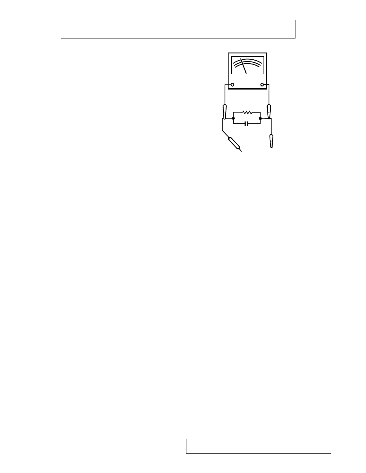
3. To be sure that no shock hazard exists, check for leakage current
in the following manner.
* Plug the AC line cord directly into a 120 volt AC outlet.
* Usingtwoclipleads,connecta1.5kohm,10wattresistorparalleled
by a 0.15µF capacitor in series with all exposed metal cabinet
parts and a known earth ground, such as conduit or electrical
ground connected to earth ground.
* Use a VTVM or VOM with 1000 ohm per volt, or higher, sensitivity
tomeasuretheACvoltagedropacrosstheresistor(Seediagram).
* Connect the resistor connection to all exposed metal parts having
areturnpathtothechassis(antenna,metalcabinet,screwheads,
knobs and control shafts, escutcheon, etc.) and measure the AC
voltage drop across the resistor.
All check must be repeated with the AC line cord plug connection
reversed.
Any reading of 0.3 volt RMS (this corresponds to 0.2 milliamp. AC.)
or more is excessive and indicates a potential shock hazard which
must be corrected before returning the audio product to the owner.
TO EXPOSED
METAL PARTS
CONNECT TO
KNOWN EARTH
GROUND
TEST PROBE
0.15 µ F
1.5k ohms
10W
VTVM
AC SCALE
Specifications for this model are subject to change without
prior notice.
SPECIFICATIONS
●MiniDisc recorder section
Type: MiniDisc recorder
Signal readout: Non-contact, 3-beam semi-conductor laser
pickup
Audio channel: Stereo; 2 channels
Monaural; 1 channel (long-time recording
mode)
Frequency response: 20 - 20,000 Hz
Rotation speed: 400 - 900 rpm CLV, Approx
Quantization: 16-bit linear
Filter: 8-times oversampling digital filter
Error correction: ACIRC (Advanced Cross Interleave Reed-
Solomon Code)
Coding: ATRAC (Adaptive TRansform Acoustic
Coding)
Recording method: Magnetic modulation overwrite method
D/A converter: 1-bit D/A converter
Sampling frequency: 44.1 kHz
Wow and flutter: Unmeasurable
(less than 0.001% W. peak)
Signal/noise ratio: 95 dB (1 kHz)
Dynamic range: 90 dB (1 kHz)
●Compact disc player section
Type: 3-disc multi-play compact disc player
Signal readout: Non-contact, 3-beam semi-conductor laser
pickup
Rotation speed: 200 - 500 rpm CLV, Approx.
Error correction: CIRC (Cross Interleave Reed-Solomon
Code)
Quantization: 16-bit linear
D/A converter: 1-bit D/A converter
Filter: 8-times oversampling digital filter
Frequency response: 20 - 20,000 Hz
Signal/noise ratio: 95 dB (1 kHz)
Dynamic range: 90 dB (1 kHz)
Wow and flutter: Unmeasurable
(less than 0.001% W. peak)
●Tuner section
Frequency range: FM; 87.5 - 108 MHz
AM; 530 - 1,720 kHz
Sensitivity: FM; 2.5 µV (75 ohms unbalanced)
AM; 650 µV/m
●Cassette deck section
Type: Compact cassette tape
Frequency response: 50 - 14,000 Hz (Normal tape)
50 - 15,000 Hz (CrO
2
tape)
Motor: DC motor with electronic governor ×1
Signal/noise ratio: 50 dB (Recording/Playback, Dolby NR off)
Dolby NR effect; 10 dB
(at over 5 kHz)
Bias and erasure
system: AC
Tape speed: 1-7/8 ips. (4.76 cm/sec.)
Wow and flutter: 0.15 % (WRMS)
Heads: Record/playback ×1
Erase ×1
●General
Power source: AC 120 V, 60 Hz
Power consumption: 101 W
Output power: 40 watts per channel minimum RMS into 6
ohms from 60 Hz to 20 kHz with no more
than 10 % total harmonic distortion
Input terminals: MD IN/AUX (Analog-1); 500 mV/47 kohms
Auxiliary (Analog-2); 500 mV/47 kohms
Auxiliary (Digital); optical
Output terminals: Auxiliary; 2.0 V/1 kohm
Headphones; 16 - 50 ohms
(recommended; 32 ohms)
Speakers; 6 ohms
Dimensions: Width; 9-1/2" (240 mm)
Height; 13-1/8" (332 mm)
Depth; 12-13/16" (325 mm)
Weight: 19.0 lbs. (8.6 kg)
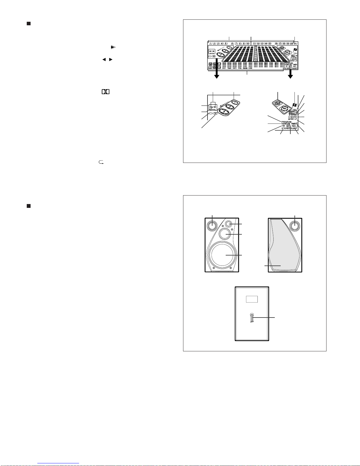
●Speaker section
Type: 3-way type [6" (150 mm) woofer, 2-1/2" (65
mm) tweeter and super tweeter]
Maximum input power: 100 W
Rated input power: 50 W
Impedance: 6 ohms
Dimensions: Width; 8-1/8" (205 mm)
Height; 13-1/8" (332 mm)
Depth; 12-3/4" (323 mm)
Weight: 9.3 lbs. (4.2 kg)/each

– 3 –
MD-X60
NAMES OF PARTS
Front panel
11. Power Button: POWER
12. Tuner Call (Band Select) Button: TUNER (BAND)
13. Preset Equalizer Button: PRE-EQ
14. Extra Bass Button: X-BASS
15. Auxiliary Input (Digital/Analog) Select Button: AUX
16. MD Compartment
17. Sampling Frequency Indicators
18. (CD) Open/Close Buttons:
19. (CD) Play Buttons: 1 , 2 , 3
10. (CD) Play/Pause Button and Indicator:
11. (CD) Stop Button:
12. Volume Up/Down Buttons: VOLUME /
13. (MD) Record Button: REC
14. Sound Synchro Record Button
15. (MD) Play/Pause Button:
16. (MD) Stop Button:
17. (MD) Eject Button:
18. CD MD Edit Button: CD MD
19. MD MD Edit Button: MD MD
20. TAPE MD Edit Button: TAPE MD
21. (CD/MD) Track Edit Button: TRACK EDIT
22. Timer/Delete Button: TIMER/DELETE
23. Display Button: DISPLAY
24. (MD) Record Mode Button: REC MODE
25. (MD) Pole Position Button: POLE POSITION
26. CD TAPE Edit Button: CD TAPE
27. MD TAPE Edit Button: MD TAPE
28. (MD) Name/TOC-Edit Button: NAME/TOC EDIT
29. (TUNER) Tuning Down Button:
3(CD) Track Down/Review Button:
3(MD) Track Down/Review/Cursor Button:
30. Jog Dial
31. (TUNER) Tuning Up Button:
3(CD) Track Up/Cue Button:
3(MD) Track Up/Cue/Cursor Button:
32. Enter Button: ENTER
33. (TAPE) Dolby NR Button: DOLBY NR
34. (TAPE) Reverse Mode Button: REVERSE MODE
35. MD Edit/Auxiliary 1 (Analog) Input Jack: MD IN/AUX 1
36. (TAPE) Fast Wind Buttons: /
37. (TAPE) Forward Play Button:
38. (TAPE) Stop Button:
39. (TAPE) Reverse Play Button:
40. (TAPE) Record Pause Button:
41. Auxiliary Input Level (Analog) Control: INPUT LEVEL
42. Cassette Compartment
43. Headphone Jack: PHONES
Rear panel
11. Auxiliary Digital Input Jack (Optical)
12. 75 Ohm FM Antenna Terminal
13. FM Antenna Ground Terminal
14. AM Antenna Ground Terminal
15. AM Antenna Terminal
16. Reset Button
17. Speaker Terminals
18. AUX 2 (Analog) Input Jacks
19. Analog Output Jacks
10. Beat Cancel Switch
11. AC Power Cord
1
2
3
5
6
7
4
28 29
23
31
21 22
30
24
32
18
19
20
25
26
27
89
13
33
34
35
16
10
11
15
12
14
17
37
38
39
40
36
41 42 43
10
1
2
3
4
5
6
9
8
7
11

MD-X60
– 4 –
Display window
11. (CD/MD) Music Schedule Indicators
12. Level Meters
13. (CD/MD) More Tracks Indicator:
14. Character Information Display
15. (TAPE) Direction Indicators: /
16. CD Indicator
17. (TAPE) Loading Indicator
18. (TAPE) Recording Indicator
19. (TAPE) Reverse Mode Indicator
10. (TAPE) Dolby NR Indicator:
11. MD Indicator
12. Pole Position Record Indicator
13. (MD) TOC Indicator: TOC
14. (MD) Record Indicator: REC
15. (MD) Sound Synchro Indicator: S.SYNC
16. (MD) Auto Mark Indicator: AUTO MARK
17. (MD) Recording Mode Indicator: MONO LP
18. Timer Play/Timer Record Indicator
19. (CD/MD) Program Indicator: PROGRAM
20. (CD/MD) Random Play Indicator: RANDOM
21. (CD/MD) Repeat Indicator:
22. FM Stereo Mode Indicator: STEREO
23. FM Stereo Indicator: ST
24. Sleep Indicator: SLEEP
Speaker section
11. Bass Reflex Duct
12. Super Tweeter
13. Tweeter
14. Woofer
15. Speaker Grille
16. Speaker Wire
1
6
23
5
7
11
8
13
14
15
16
17
18
242322
21
20
19
9
12
4
10
1
2
3
45
6
1

– 5 –
MD-X60
Remote control
11. Remote Control Transmitter LED
12. (MD/CD/TUNER) Direct Key
13. (CD/MD) Program Button: PROGRAM
14. (CD/MD) Program Clear Button: CLEAR
15. (CD/MD) Play Mode Button: P-MODE
Tuner control section
16. Tuner Call (Band Select) Button: TUNER/BAND
17. FM Stereo Mode Button: ST MODE
MD control section
18. Record Button: REC
19. Track Up,Cue/Down,Review Buttons: /
10. Stop Button:
11. Play/Pause Button:
12. Sound Synchro Record Button: S.SYNC
13. Auto Mark Button: A.MARK
14. Record Mode Button: REC MODE
CD control section
15. Track Up,Cue/Down,Review Buttons: /
16. Play/Pause Button:
17. Stop Button:
18. Play Buttons: 1 , 2 , 3
19. Auxiliary Input (Digital/Analog) Select Button: AUX
20. Display Button: DISPLAY
21. Time Display Select Button: TIME
Tape control section
22. Fast Wind Buttons: /
23. Stop Button:
24. Play Buttons: /
25. Record Pause Button:
26. Dolby NR Button: DOLBY NR
27. Reverse Mode Button: REVERSE MODE
28. Power Button: POWER
29. Extra Bass Button: X-BASS
30. Volume Up/Down Buttons: /
31. Pre-programed Equalizer Button: PRE-EQ
2
347
5
9
6
19
15
27
21
10
8
20
30
11
12
13
31
14
17
26
24
16
22 23
25
28
29
18
1

MD-X60
– 6 –
SETTING THE CLOCK
(Main unit operation)
1
Press the POWER button to turn the power on.
2
Press the TIMER/DELETE button.
3
Within 10 seconds, turn the jog dial until "TIME ADJUST" appears.
4
Within 10 seconds, press the ENTER button.
The unit will enter the date setting mode.
5
Adjust the "month" using the jog dial.
When you turn the jog dial and let go, the month will change up or down by
one. When you turn and hold it, the month will change continuously.
6
Press the ENTER button to set the "month".
7
Adjust the "day" using the jog dial.
8
Press the ENTER button to set the "day".
9
Adjust the "year" using the jog dial.
The year 2000 or later is set as follows:
[00] indicates the year 2000.
[01] indicates the year 2001.
The range of dates that can be entered is from January 1, 1997 to December
31, 2099.
10
Press the ENTER button to set the "year".
The unit will enter the time setting mode.
11
Adjust the "hour" using the jog dial.
When you turn the jog dial and let go, the hour will change up or down by one.
When you turn and hold it, the hour will change continuously.
On the display, midnight is "AM 12:00" and noon is "PM 12:00". When setting
the time, be careful not to confuse AM and PM.
12
Press the ENTER button to set the "hour".
13
Adjust the "minute" using the jog dial.
14
Press the ENTER button to set the "minute".
The clock starts operating from "0" seconds. (Seconds are not displayed.)
POWER
TIMER /
DELETE
ENTER
2
14
12
13
3
4
5
6
7
8
9
10
11
Notes:
In the event of a power failure or when the AC power cord is disconnected, the
clock setting will be lost. Reset the time.
While recording an MD, you cannot set the date and clock. Be sure to set the
date and clock before recording.
Resetting the date and time:
Once you have set the date and time, "TIME ADJUST" will not be displayed in
step 2. Turn the jog dial to make the date and time appear.
If you don't need to change the settings, just press the ENTER button without
turning the jog dial again.
Checking the date and time:
Press the TIMER/DELETE button. Then turn the jog dial until the date and time
are displayed.
Press the DISPLAY button to switch between the date and the time.
After about 10 seconds, the original display will appear.
Once the date and the time have been set, this unit will normally display the
time when the unit is in the stand-by mode.
To check the date, press the DISPLAY button.
The display will switch between the date and the time each time you press the
button.
Jog dial
Date setting mode
Time setting mode
MINIDISC SYSTEM LIMITATIONS
Even if the maximum recording time of a MiniDisc has not
been reached, "TOC FULL" may be displayed.
Even if the maximum recording time of a MiniDisc has not
been reached, "DISC FULL" may be displayed.
Even if several short tracks are erased, the remaining
recording time may not show an increase.
Two tracks may not be combined in editing.
The total of the recorded time and time remaining on a
disc may not add up to the maximum possible recording
time.
If recorded tracks are fast reversed or fast forwarded, the
sound may skip.
In the MD system, the delimiter of the recording area on an MD is programmed
in a TOC. If partial erasing, recording and editing are repeated several times,
TOC information will fill up, even though the number of tracks has not reached
the limit (255 tracks), and further recording will be impossible. (If you use the all
erase function, this MD can be used from the beginning.)
If there is any flaw on the MiniDisc, that part is automatically excluded from the
space available for recording. Therefore, the recording time becomes shorter.
When the remaining recording time of a disc is displayed, short tracks less than
12 seconds long may not be included in the total.
For MiniDiscs on which repeated recording and editing operations were per-
formed, the COMBINE function may not work.
A track recorded from a CD (digital recording) and a track recorded from a radio
or other equipment (analog recording) cannot be combined.
A cluster (about 2 seconds) is normally the minimum unit of recording. So, even
if a track is less than 2 seconds long, it will use about 2 seconds of space on
the disc. Therefore, the time actually available for recording may be less than
the remaining time displayed.
If there are scratches on discs, those sections will be automatically avoided (no
recording will be placed in those sections). Therefore, the recording time will be
reduced.
An MD which has been recorded or edited repeatedly may skip during fast reverse
or fast forward.
TROUBLESHOOTING
If a problem occurs
If this unit functions abnormally during operation, first check the following items. If the unit continues to function abnormally, or if an abnormality
appears other than listed below, turn off the player's power and disconnect the AC power plug, then consult your SHARP dealer or service
personnel.
General
SYMPTOM POSSIBLE CAUSE REMEDY
The clock is wrong. Did a power failure occur? Try setting it again.
When a button is pressed, the unit does
not respond. Set this unit to the stand-by mode and then
turn it back on. Then, retry the operation.
No sound is heard. Is the volume level is set to "0"?
Are the headphones connected?
Are the speaker wires disconnected?
Increase the volume level.
Disconnect the headphones.
Connect the wires securely.
Radios make unusual noise or the picture
on the TV screen is distorted. When a radio or TV which uses an indoor
antenna is placed near the unit, the picture
on the TV screen may be distorted or the
radio may not function properly.
It is recommended that you use an external
antenna.
CD playback
SYMPTOM POSSIBLE CAUSE REMEDY
Even though a disc has been loaded, "NO
DISC" or "ERR" is displayed.
Playback stops in the middle of a track, or
playback is not performed properly.
Playback sounds are skipped.
The disc is loaded up-side down.
The disc is very dirty.
The disc which does not satisfy the stand-
ards.
Is the unit located near excessive vibra-
tions?
Has condensation formed inside the unit?
Load the disc with the correct side up.
Clean the disc.
Load the correct disc.
Place the unit on a firm, level surface free
from vibration.
Remove the disc and leave the power
turned on. The unit should function properly
in about 1 hour.
OPERATION MANUALNAMES OF PARTS

– 7 –
MD-X60
(Continued)
MD recording and playback
SYMPTOM POSSIBLE CAUSE REMEDY
A recording cannot be made. Is the MiniDisc protected against accidental
erasure?
Did you try to make recording on a
playback-only MiniDisc?
Can you see the "TOC FULL" message in
the display?
Slide the accidental erase prevention tab
back to its original position.
Replace it with a recordable disc.
Put in another recordable disc with record-
ing space on it.
Even though a disc has been loaded, "NO
DISC" or "ERR" is displayed.
Playback sounds are skipped.
The disc is very dirty.
Is the unit located near excessive vibra-
tions?
Has condensation formed inside the unit?
Clean the disc.
Place the unit on a firm, level surface free
from vibration.
Remove the disc and leave the power
turned on. The unit should function properly
in about 1 hour.
Tape recording and playback
SYMPTOM POSSIBLE CAUSE REMEDY
A recording cannot be made. Is the tape protected against accidental
erasure? Cover the accidental erase prevention hole.
Sound is skipped.
Sound in high-frequency range cannot be
reproduced.
Sound quivers.
The tape is damaged.
The capstan and pinch roller are very dirty. Replace the tape.
Clean the capsten and pinch roller.
The cassette cannot be ejected. Did a power failure occur? Wait until the power is supplied.
Radio reception
SYMPTOM POSSIBLE CAUSE REMEDY
Radios make unusual noise consecutively. The unit is placed near the TV or computer.
The antenna direction is not placed proper-
ly.
When the unit receives a radio broadcast
near a TV set, a computer or a wordproces-
sor, it may pick up noise. If this happens,
try to move the unit from the place where
the noise is picked up.
Correct the antenna direction.
The preset channel cannot be recalled. Did you erase the programmed station? Preset the channel again.
Redo programming.
Remote control
SYMPTOM POSSIBLE CAUSE REMEDY
The remote control does not function or
does not operate properly. The batteries (polarity) are not inserted
properly.
The batteries inside the remote control are
dead.
The remote control is operated from an in-
correct distance or angle.
Insert properly.
Replace the batteries.
Operate it within a range of 8" (0.2 m) to
20' (6 m) and within an angle of 15 °to
either side of center.
The power cannot be turned on from the
remote control. Is the AC power cord plugged in? Connect the AC power cord.
(Continued)
If a problem occurs
If this product is subjected to strong external interference (mechanical
shock, excessive static electricity, abnormal supply voltage due to
lightning, etc.) or if it is operated incorrectly, it may malfunction or the
display may not function correctly. If such a problem occurs, do the
following:
Connect the AC power cord to the AC outlet, and press the RESET
button once on the rear of the main unit.
When the RESET button is pressed, all of the contents in memory
(clock and timer settings, and CD presets) other than the tuner sta-
tions will be erased.
If strange sounds, smells or smoke come out of the unit or if a foreign
object falls into the unit, turn off the power, unplug the AC power
cord from the AC outlet, immediately. Contact the shop where you
purchased the unit.
(Continued)
When an error message is displayed, proceed as follows:
Error messages Meaning Remedy
BLANK MD
Nothing is recorded. Replace it with another disc.
Can't COPY
You tried to record from a copy-protected disc. Replace it with a regular disc that can be copied.
Can't EDIT
A track cannot be edited. Change the stop position of the track and then try editing
it.
Can't REC
Recording cannot be performed correctly due to vibra-
tion or shock in the unit. Re-record.
Can't T REC
Timer recording is impossible or there is no available
space on the MD. Replace it with another disc.
CH ERROR
There is something wrong with the CD changer. Set this unit to the stand-by mode and then back to on,
and press the button.
CONNECT ERR
While an MD player is being edited on this unit, incorrect
digital signals are input from the portable MD player. Make sure the cable is connected correctly and that
power is being supplied to the portable MD player.
DEFECT
Since this disc has scratches on it, the recording opera-
tion was skipped. Replace it with another disc.
Din UNLOCK
Incorrect digital signals are input. Connect correct digital signals.
Use the analog input jacks.
DISC ERR
The disc is damaged.
A TOC is not written on the MD or there is something
wrong with data.
Reload the disc or replace it.
DISC FULL
The disc is out of recording space. Replace the disc with another recordable disc.
EDIT OVER
There is no space to make CD editing on the disc. Replace it with a disc that has enough time to record.
FOCUS ERROR
A disc has not been loaded.
The disc data cannot be read. Reload the MiniDisc.
MD ERROR
No operation. Contact the shop where you purchased the unit.
MECHA ERR∗
(∗:Number or
symbol)
There is a mechanical problem and the disc is not work-
ing properly. Set this unit to the stand-by mode and press the but-
ton.
NAME FULL
The number of characters for the disc name or track
name exceeds 100. Shorten the disc or track name.
NO DISC
A disc has not been loaded.
The disc data cannot be read. Load a disc.
Reload the disc.
NOT AUDIO
The data recorded on this disc is not audio data. Select another track.
Replace the disc.
PLAYBACK MD
You tried to record on a playback-only disc. Replace it with another recordable disc.
PROTECT
Trouble is found. Restart the unit. If the unit doesn't work, contact a
SHARP Authorized Servicing Dealer or SHARP
Authorized Service station.
PROTECTED
The disc is write protected.
The tape is protected against accidental erasure. Move the write protection tab back to its original position.
Cover the accidental erase prevention hole.
TAPE ERROR
The tape mechanism is defective. Try pressing the RESET button.
TEMP OVER
The temperature is too high. Set this unit to the stand-by mode and wait for a while.
TOC ERR∗
(∗:Number or
symbol)
The disc is damaged.
TOC information cannot be read.
MD not specified.
Replace it with another disc.
TOC FULL∗
(∗:Number or
symbol)
There is no space left for recording character information
(track names, disc names, etc.). Replace it with another recordable disc.
TOC W ERROR
Recording is impossible. Contact the shop where you purchased the unit.
TRAY ERROR
The CD tray operates incorrectly. Unplug the AC power cord, plug it back, and then turn
the power on.
U TOC ERR∗
(∗:Symbol)
TOC information recorded on the MD does not match
the MD specifications or it cannot be read. Replace it with another disc.
Erase all of the track, and try recording.
U TOC W ERR
The TOC information could not be created properly due
to a mechanical shock or to scratches on the disc. Turn off the power, and try to write the TOC again.
(Remove any source of shock or vibration while writing.)
? DISC
The data contains an error. Replace it with another disc.
00:00
Music is not being recorded. Replace the disc with another recordable disc.

MD-X60
– 8 –
MD / CD COMPONENT
SYSTEM
MD-X60
Quick-Guide
Guía rápida
Conexión
Connection
Remote control
Controlador remoto
12 3
FM Antenna
Antena de FM
AM Loop Antenna
Antena de cuadro de AM
Right Speaker
Altavoz derecho
Left Speaker
Altavoz izquierdo
AC 120V, 60Hz
120V CA, 60Hz
15
15
The sound level at a given volume setting
depends on a combination of speaker efficiency,
location and various other factors. It is advisable
to avoid exposure to high volume levels, which
can occur while turning the unit on with the
volume control setting up high, or while continu-
ally listening at high volume levels.
El nivel de sonido en una posición de volumen
fijado depende de una combinación del
rendimiento de las altavoces, la posición y varios
otros factores. Es aconsejable evitar un aumento
de volumen. Esto se produce, por ejemplo, al
conectar el aparato con el volumen puesto en
una posición alta. Evite continuar la audición
prolongada a altos niveles de sonido.
Volume setting
Ajuste del volumen
Precaution
Precaución
Volume control
Control del volumen
Volume
Extra-BASS
Graves extra
Remote sensor
Sensor remoto
Connecte el cable negro al terminal negativo (-), y el
cable rojo al terminal positivo (+).
Connect the black wire to the minus (-) terminal, and
the red wire to the plus (+) terminal.
Pre-programmed equalizer
Volumen
Ecualizador preprogramado
8" - 20' (0.2 m - 6 m)
0,2 m - 6 m
2 "AA" batteries
Dos pilas "AA"
FLAT
HEAVY-2
HEAVY-1
SOFT-1
SOFT-2
VOCAL
To an AC outlet
A un tomacorriente de CA
CD playback
Reproducción de
discos compactos Reproducción de un
minidisco
Playing a MiniDisc Tape playback
Reproducción de cintas
TINSZ0338AWZZ
Etiqueta hacia arriba.
Label facing up.
Funcionamiento de la
radio
Radio operation
Edición con una
pulsación
(CD MD)
One-touch editing
(CD MD)
One-touch editing
(TAPE MD)
Edición con una
pulsación
(TAPE
MD)
Edición con una pulsación
(CD
TAPE) (MD TAPE)
CD TAPE
Printed in Malaysia
Impreso en Malaysia
A9805.YO
(CD)
(CD)
(CD)
(CD)
(CD)
(MD)
(MD)
(MD)
(CD)
(CD)
(MD)
(TAPE)
(TAPE)
(TAPE)
One-touch editing
(CD TAPE) (MD TAPE)
(TAPE)
MD TAPE
QUICK GUIDE

– 9 –
MD-X60
Caution on Disassembly
The disassembling the machine or assembling it after
repair, observe the following instructions so as to ensure
safety and keep its performance.
1. Unload the compact disc, and mini-disc, casette tape
from machine.
2. Be sure to unplug the power cable before starting
disasembly of the machine.
3. When disassembling each section, remove the nylon
band or wire arrangement.
After servicing the unit, be sure to rearrange the leads
where they were before disassembling.
Ifascrew of improperlengthis fit totheMD mechanism.
(a screw fit the part to the mechanism chassis of MD
section), it may contact the optical pickup, impeding
normal operation. Hence, due care must be taken.
4. While repairing, pay utmost attention to static electricity
on ICs.
Figure 9-1
Note 1: After removing the connector for the optical pickup
fromtheconnectorwraptheconductivealuminiumfoil
around the front end of connector so as to protect the
optical pickup from electrostatic damage.
DISASSEMBLY
1 Cabinet 1. Screw ................ (A1) x9 9-1
2 Rear Panel 1. Screw ................ (B1) x14 9-1
(Upper,Bottom)
3 CD Changer Block 1. Screw ................ (C1) x6 10-1
2. Screw ................ (C2) x2
4 Main PWB 1. Screw ................ (D1) x3 10-1
2. Socket ............... (D2) x6
3. Flat Cable.......... (D3) x3
4. Socket ............... (D4) x2
5 Fan Motor 1. Socket ............... (E1) x1 10-2
2. Screw ................ (E2) x2
6 Power Amp. PWB 1. Socket ............... (F1) x2 10-2
2. Lug Wire............ (F2) x1
3. Screw ................ (F3) x3
7 Fuse PWB 1. Screw ................ (G1) x2 10-2
8 MD Holder 1. Screw ................ (H1) x4 10-2,3
9 MD Unit 1. Screw ................ (J1) x2 10-3
10 Front Panel 1. Socket ............... (K1) x1 10-4
2. Screw ................ (K2) x5
11 Power PWB 1. Screw ................ (L1) x5 10-4
12 Tape Mechanism 1. Screw ................ (M1) x4 10-5
13 Tray Switch PWB 1. Screw ................ (N1) x2 10-5
2. Socket ............... (N2) x1
14 Display PWB 1. Screw ................ (P1) x9 10-5
2. Flat Cable.......... (P2) x1
15 Switch A PWB 1. Screw ................ (Q1) x2 10-5
16 Switch B PWB 1. Knob.................. (R1) x1 10-5
2. Nut..................... (R2) x1
3. Screw ................ (R3) x5
4. Screw ................ (R4) x1
17 Jack PWB 1. Socket ............... (S1) x1 10-5
2. Screw ................ (S2) x1
18 Level Volume PWB 1. Screw ................ (T1) x1 10-5
19 Headphone PWB 1. Screw ................ (U1) x1 10-5
STEP REMOVAL PROCEDURE FIGURE
MAIN UNIT
20 CD Mechanism 1. Screw ................ (V1) x7 11-1
2. Top Bord ........... (V2) x1
3. Disc Holder ....... (V3) x1
4. Disc Tray ........... (V4) x3
5. Screw ................ (V5) x3
6. Mechanism Holder
Guide ................. (V6) x1
7.
Mechanism Holder
(V7) x1
8. Screw ................ (V8) x4
21 MD Mechanism 1. Screw ................ (W1) x8 11-2
22 MD Main PWB 1. Screw ................ (X1) x4 11-3
(Note 1 ) 2. Socket ............... (X2) x5
3. Flat Cable.......... (X3) x1
23 MD Mechanism 1. Screw ................ (Y1) x4 12-1
STEP REMOVAL PROCEDURE FIGURE
(A1) x5
ø3 x8mm
(A1) x2
ø3 x8mm
(A1) x2
ø3 x8mm
(B1) x3
ø3 x8mm
(B1) x11
ø3 x8mm
Cabinet Front Panel
Rear Panel
(Upper)
Rear Panel
(Bottom)
MAIN UNIT
Cares after repairing
Aftercompletionofrepairofproductsetthefollowingshipping
mode to return.
1.MakesurethatthereisnoCDdisc,andthenpresstheVOL-
UP/CDDISC1PLAYbuttontoturnonthepower,andsetthe
TEST mode.
2.AftertheindicationofTESTENDappears,unplugthepower
cord. If this test mode is executed, the data stored by the
user in the preset memory are all cleared. It is necessary
tell and obtain the consent of user in advance.

MD-X60
– 10 –
Figure 10-1
Figure 10-2
Figure 10-3
Figure 10-4
Figure 10-5
(C1) x6
(D2) x6
(D4) x2
(D3) x1
(D3) x2
(C2) x2
ø3 x10mm
(D1) x1
ø3 x10mm
(D1) x2
ø3 x10mm
Front Panel
Pull
Pull
Pull
Pull
CD Chenger
Block
Main PWB
(F3) x1
ø3 x10mm
(F1) x1
(F1) x1
(E1) x1
(E2) x2
ø3 x10mm
(G2) x2
ø3 x10mm
(H1) x1
ø3 x10mm
(H1) x2
ø3 x10mm
(F3) x2
ø3 x12mm
(F2) x1
Lug wire
Front Panel
MD Unit
MD Holder
Fuse PWB
Power Amp.
PWB
Fan Motor
(J1) x1
ø3 x10mm
(J1) x1
ø1.7 x3mm
(H1) x1
ø3 x10mm
Front Panel
MD Holder
MD Unit
(K1) x1
(L1) x1
ø3 x8mm
(K2) x2
ø3 x10mm (K2) x3
ø3 x8mm
(L1) x4
ø4 x8mm
Front Panel
Power PWB
Pull
Pull
(R1) x1
(R2) x1
(P2) x1
(N2) x1
(S1) x1
(N1) x2
ø3 x10mm
(P1) x9
ø3 x10mm
(R3) x5
ø3 x10mm
(R4) x1
ø3 x8mm
(S2) x1
ø3 x10mm
(T1) x1
ø3 x10mm
Lug Wire
(Q1) x2
ø3 x10mm
(M1) x4
ø3 x10mm
(U1) x1
ø3 x10mm
Front Panel
Washer
Pull
Pull
Display PWB
Tray Switch PWB
Switch B PWB
Headphone PWB
Switch A PWB
Leve Volume PWB
Jack PWB
Tape Mechanism

– 11 –
MD-X60
Figure 11-1
Figure 11-2 Figure 11-3
(V1) x2
ø2 x7mm
(V5) x2
ø2 x6mm (V1) x1
ø3 x10mm
(V1) x2
ø3 x8mm
(V1) x2
ø3 x10mm
(V5) x1
ø2.6 x12mm
(V8) x4
ø2.6 x10mm
(V3) x1
(V2) x1
(V6) x1
(V7) x1
1
2
3
PWB-B8
Disc Tray 2
Disc Tray 3 Press in turns the arrow
parts, starting with the
uppermost one, to
withdraw the disc trays
Disc Tray 1
Turn clockwise the
main cam to raise the
CD mechanism up to
the uppermost position.
CD
Mechanism
Pawl
Push
.
Spring
(V4) x3
(W1) x 1
ø2 x 4mm
(W1) x 1
ø2 x 4mm
(W1) x 1
ø3 x 10mm
(W1) x 1
ø3 x 10mm
(W1) x 1
ø2 x 4mm
(W1) x 1
ø2 x 4mm
(W1) x 1
ø3 x 10mm
(W1) x 1
ø3 x 10mm
MD Unit
shield Case(Upper)
shield Case(Below)
MD Holder
MD Holder
Bracket
(X3)x1
(X2)x1
(X2)x3
(X2)x1
(X1)x4
ø1.7 x 3mm
MD Main PWB
Pull
(W4) x1
Chassis
Optical pickup
Flexible PWB
(Note 1)
(Note 1) After removing the flexible PWB for optical pickup
from the connector wrap the front end of flexible PWB in
conductive aluminum foil so as to protect the optical pickup
from being damaged electrostatically.

MD-X60
– 12 –
Figure 12-1
Figure 12-2 Figure 12-3
(Y1)x4
ø1.7x8.9mm
MD Mechanism
( A1 ) x1
( A2 ) x1
Woofer
Front Panel
Super Tweeter
Tweeter
Net
( A3 ) x2
ø3x10mm
( A3 ) x3
ø3x8mm
( A3 ) x1
ø3x6mm
( A3 ) x4
ø4x16mm
Woofer
Super Tweeter
Tweeter
Front Panel
1 Speaker 1. Net..................... (A1) x9 12-2
2. Front Panel ....... (A2) x9
3. Screw ................ (A3) x9 12-3
STEP REMOVAL PROCEDURE FIGURE
SPEAKER
SPEAKER

– 13 –
MD-X60
REMOVINGAND REINSTALLING THE MAIN PARTS
MD MECHANISM SECTION
Perform steps 1 to 9,21 and 23 of the disassembly method to
remove the MD mechanism.(Refering to p.9~12)
How to remove the magnetic head
(See Fig. 13-1)
1. Remove the screws (A1) x 1 pc.
Caution:
Takeutmostcaresothatthemagneticheadisnotdamaged
when it is mounted.
How to remove the cartridge holder
(See Fig. 13-2)
1. Open the rpller arm lever in the arrow direction, and lower
the clamper lever to the rear side.
2. Apply +5V to the red line side of blue connector of loading
motor,pushtherackgearinthearrowdirectiontomovethe
cam plate lever until tick is heard.
3. Remove the screw (B1) x1 pc., and the spring (B2) x1 pc.,
fitted to the holder arm, and shift the cartridge holder to the
left side to remove it.
How to remove the mechanism switch PWB
(See Fig. 13-3)
1.Removethescrews(C1)x2pcs.,andremovethemechanism
switch PWB.
Figure 13-1
Figure 13-2
Figure 13-3
MD Mechanism
(A1)x1
ø1.7x5mm
Magnetic Head
Slider Lever
Cartridge Holder
Clampa Lever
Lack Gear
Roller Arm Lever
Loading Motor
Cam Plate Lever
(B1) x1
Ø1.7x5mm
(B2) x1 Holder Arm
(C1)x1
Ø1.7x3mm
(C1)x1
Ø1.7x9.5mm

MD-X60
– 14 –
Figure 14-2
Figure 14-3
How to remove the spindle motor
(See Fig. 14-2)
1. Remove the screws (E1) x 3 pcs., and remove the spidle
motor.
Caution:
Be careful so that the turntable is not damaged.
How to remove the optical pickup
(See Fig. 14-3)
1. Remove the screws (F1) x 3 pcs.
Caution:
Be careful so that the gear is not damaged.
(The damaged gear emits noise during searching.)
How to remove the sled motor/loading motor
(See Fig. 14-1)
1. Remove the screws (D1) x 4 pcs., and remove the sled
motor/loading motor.
Caution:
Be careful so that the gear is not damaged.
(The damaged gear emits noise during searching.)
Figure 14-1
Spindle Motor
Turntable
Gear
(E1)x3
Ø1.7x2.5mm
Optical Pickup
(F1)x3
Ø1.7x9.5mm
Gear
Sled
Motor
Loading
Motor
Gear
(D1)x2
Ø1.7x2mm (D1)x2
Ø1.7x2mm

– 15 –
MD-X60
Figure 15-1
Figure 15-2
CD MECHANISM SECTION
For the procedure to remove the CD mechanism from the
main unit, refer to Disassembling Procedure, Steps 1~3, and
20. (p.9~11).
How to Remove the optical pickup
(See Fig. 15-1.)
1. Remove the screws (A1)x 2 pcs., to remove shaft (A2)x 1
pc.
2.Removestopwasher(A3)x1pc.,toremovegear(A4)x1pc.
3. Remove the optical pickup.
Note:
After disconnecting the optical pickup connector wrap the
front end of connector in conductive aluminum foil so as to
prevent damage to the optical pickup by static electricity.
How to Remove the tray motor/main cam motor
(See Fig. 15-2.)
1. Remove the CD changer section by the method described
in page 8, and disassemble as shown in the figure.
2. Remove the belts (B1)x 2 pcs., from the motor side.
3. Remove the screws (B2)x 4 pcs.
4. Remove the tray motor and main cam motor.
How to remove the CD disc
(When CD exists in the tray)
(See Fig. 15-4.)
1. Remove the cabinet and front panel.
2. Disassemble as shown in the figure so that the CD disc of
CD changer can be taken out.
3. Remove the CD disc from the tray as shown in the figure.
How to remove the CD disc
(When CD is in playback state)
(See Fig. 15-3.)
1. Remove the cabinet and front panel.
2. Disassemble as shown in the figure so that the CD disc of
CD changer becomes visible.
3. Remove the CD disc as shown in the figure.
Figure 15-3
Figure 15-4
(A1) x2
ø2.6 x5mm
CD
Mechanism
Stop Washer
(A3) x1
Gear
(A4) x1
Shaft
(A2) x1
Pickup
Tray Motor
Main Cam
Motor
Belt
(B1) x1 Belt
(B1) x1
(B2) x2
ø2.6 x4mm
(B2) x2
ø2.6 x4mm
CD Disc
Disc Holder
CD Changer
Block
(When CD is in playback state.)
Turn the main cam clockwise,
and raise the CD mechanism
and disc holder up to
uppermost position.
1
2
3
Disc Tray 1
Disc Holder
CD Disc
Disc Tray
2
Disc Tray
3
CD Mechanism
Press in turns the arrow
parts, starting with the
uppermost one, to
withdraw the disc trays
Turn the main cam clockwise,
and raise the CD mechanism
and disc holder up to
uppermost position.
CD Changer
Block
(When CD exists in the tray.)

MD-X60
– 16 –
ADJUSTMENT
fL: Low-range frequency
fH: High-renge frequency
• AM adjustment and confirmation
Figure 16-1 AM IF
TUNER SECTION • TEST mode setting method
Holdingdownthe ENTERbuttonand TUNER(BAND) button,
turn on the power. Frequency is set in the memory (initial
setting) as shown in Table 16. Call the setting with the
PRESET button to use it for tuner circuit adjustment or
confirmation.
Preset No. Frequency
P01 87.5 MHz P06 530 kHz
P02 108.0 MHz P07 1,720 kHz
P03 90.0 MHz P08 600 kHz
P04 106.0 MHz P09 1,400 kHz
P05 98.0 MHz P10 990 kHz
Adjusting item Adjusting object Adjusting
method
IF Adjust the indication of Set IF wafeform
T351 set to 1,720 kHz.
450 kHz to maximum.
Frequency cover fL: T306 (530 kHz) fL: 1.1 ± 0.1 V
(VT line voltage of Adjust the indication fH: 5.1 ± 1.3 V of
pin 20 of IC302) of set to 522 kHz. (Only confirmation)
Tracking fL: T302 (990 kHz) Set the output of
speaker terminal
to maximum.
AM signal oscillator Frequency 400 Hz, 30%, AM modulation
• FM mute level adjustment
Frequency Adjusting
object
Adjusting
method
98 MHz 30 dB VR351 Input: SO301
Output: Speaker
Terminal
FM signal oscillator Frequency 400 Hz, 22.5 kHz
Adjusting object
Preset No. Frequency
Figure 16-2 FM Mute Level
Table 16 Initial setting of memory
GND
AM Loop Antenna
Loop Antenna
Electronic
voltmeter
IF : Speaker Terminal
Freqency cover: IC302,Pin 20
UNIT
FM signal oscillator
SO301
Electronic
voltmeter
Speaker
Terminal
UNIT
FM signal oscillator
1
1213
VR351
T306
T351
IC302
T302
FE301
AM IF
20
TUNER PWB
FM Mute Level
AM Band Coverge
AM Tracking
SO301
Antenna Terminal
Figure 16-3 Adjustment Point
• Erasing the registered broadcast station
Holding down TRACK EDIT and ENTER in power-off state,
press POWER.
All the registered stations are erased.
Note:
EvenwhentheRESET switch providedattherear side ofthis
model, is pressed, the preset of tuner is not cleared.

– 17 –
MD-X60
TAPE SECTION
CNP102
CNP930
VR103
VR105
VR106
VR107
CNP103
VR104
TP102
TP101
Pin 1 : R
Pin 3 : L
IC102
CNP101
VR102
VR101
CNP920
3
1
2
3
L-CH
REC FREQUENCY
R-CH
REC FREQUENCY
L-CH
PLAY SENS.
R-CH
PLAY SENS.
TAPE
SPEED
L-CH
REC SENS.
R-CH
REC SENS.
MAIN PWB
Figure 17 Adjustment Point
Play:TW-2412 120 g or more
Reverse Play:TW-2422 120 g or more
Driving Force Check
Torque Meter Specified Value
Play:TW-2111 25 to 65 g.cm
Reverse Play:TW-2121 25 to 65 g.cm
Fast forward:TW-2231 60 to 130 g.cm
Rewind:TW-2231 60 to 130 g.cm
Checking the playback/FF/rewinding torque
Torque Meter Specified Value
MTT-114 Output: L:TP102 pin 3
R:TP102 pin 1
Adjusting the record / playback head azimuth
Test Tape Instrument Connection
MTT-111 VR107 3,000±30Hz L:TP102 pin 3
R:TP102 pin 1
Tape Speed
Test Tape
Adjusting Point Specified Value Instrument Connection
* Raise the cassette holder cover and remove it, and then
adjust the azimuth.
- 102±7kHz TP101(IC102 pin 3)
Checking the bias oscillation Frequency
Adjusting Point Specified Value Instrument Connection
Adjusting the deck circuit
Adjusting the mechanism
VOLUME MAX
FUNCTION TAPE
TAPE NORMAL
DOLBY NR OFF
REVERSE MODE NORMAL
BEAT SW A
Position of each swich or control
Adjusting the record/playback frequency
MTT-150 L:VR103 Standard:300mV L:TP102 pin 3
R:VR104 R:TP102 pin 1
Adjusting the playback amplifier sensitivity
Test Tape
Adjusting Point
Specified Value
Instrument Connection
Record level control
100mV Input:AUX
(1kHz)
UR-121 L:VR105 100mV Output
R:VR106 L:TP102 pin 3
R:TP102 pin 1
Adjusting the record/playback sensitivity
Test Tape
Adjusting Point
Specified Value
Instrument Connection
Record level control
10mV Input:AUX
(10kHz)
UR-121 L:VR101 10mV Output
R:VR102 L:TP102 pin 3
R:TP102 pin 1
Test Tape
Adjusting Point
Specified Value
Instrument Connection

MD-X60
– 18 –
CD TEST MODE
CD test mode setting
Any one of test mode can be set by pressing several buttons as follows.
Holding down VOL-UP and CD DISC 3 PLAY, turn on POWER. TEST: CD operation test
Test Mode
Function - CD TEST mode
Setting of Test mode
Indication of CD TEST mode
OPEN/CLOSE operation is manual operation.
The pickup can be moved with the ( ) or ( ) button.
<CD MD EDIT> <TRACK> <CD-STOP>
Tracking on the spot. Tracking on the spot. STOP
SERVO ON PLAY SERVO OFF PLAY
<PLAY> button input - TOC. Initialization performed, and the ordinary PLAY is performed.
Press the <STOP> button. Stop
If the following button is pressed during PLAY, it is possible to specify directly any Track No.
<Disc 1 PLAY> button: Track 4
<Disc 2 PLAY> button: Track 9
<Disc 3 PLAY> button: Track 15
Note:
Only in STOP state it is possible to slide the pickup with the ( ) or ( ) button.
Cancel method: POWER OFF
Initialization is not performed.
CD SECTION
Since this CD system incorporates the following automatic adjusting function, when the pickup is replaced, it is not necessary
to the readjust it .
Since this CD unit does not need adjustment, the combination of PWB and laser pickup unit is not restricted.
Automatic adjustment items
1. Focus Offset (Fig. 18-1)
2. Tracking Offset (Fig. 18-2)
3. E/F Balance (Tracking Error Balance) (Fig. 18-3)
4. R/F level AGC function (HF level: Constant)
5. RF level automatic follow-up of the tracking gain
This automatic adjustment is performed each time a disc
is changed. Therefore, each disc is played back using
the optimal settings.
Figure 18-1
Figure 18-2 Figure 18-3
2
0.1s
0.50 V
IC1 20 FE
0.1s
0.50 V
IC1 7 TE
1
FOCUS
OFF-SET
ADJUST
TRACKING
OFF-SET
ADJUST
2
1
10ms
0.50 V
IC1 20 FE
10ms
0.50 V
IC1 7 TE
Enlarged
View
TRACKING
OFF-SET
ADJUST
2
1
TO
TE
200 ms
1V/diV
IC 1 15
200 ms
1V/diV
IC 1 7
TRACKING/
ERROR
BARANCE
ADJUST

– 19 –
MD-X60
1. Preparation for adjustment
Test disc
MD SECTION
Type Test disc Part No.
1 High reflection disc TGYS1 (SONY) [for Playback] RRCDT0101AFZZ
2 Low reflection disc Recording minidisc UDSKM0001AFZZ
3 Head Adjusting transparent RRCDT0103AFZZ
[TEAC Test MD]
4 Low reflection disc Pre-adjustment disc 88GMMD-318
Extension Cable (See Fig. 19)
Type Part No.
1 Extension PWB for servicing RUNTK0457AFZZ
2 Extension Connector (2 Pin) QCNWK0059AFZZ
3 Extension Connector (6 Pin) QCNWK0107AFZZ
4 Extension Cable (5 Pin) QCNWK0109AFZZ
5 Extension Cable (28 Pin) QCNWK0108AFZZ
When the combination of mechanism/pickup and PWB was changed , set the TEST mode to perform the AUTO preliminary
adjustment and AUTO adjustment, write the adjustment data in EEPROM.
When EEPROM was replaced, set the TEST mode,write the EEPROM set data (p28,p29) and then perform the preliminary
adjustment and AUTO adjustment, write adjustment data in EEPROM.
Figure 19 Conection of Extention Cable
5Pin extension flat cable
QCNWK0109AFZZ
2Pin extension connector
QCNWK0059AFZZ
CN1601(Bottom side)
CN1602
CN1252
CN1603
CN1604(Bottom side) CN1101
MD MAIN PWB
6P-2P extension connector
QCNWK0107AFZZ
28Pin extension
flat cable
QCNWK0108AFZZ Extension PWB for service
(RUNTK0457AFZZ)
Fit the extension PWB for service to the mechanism
From Optical
Pickup Unit
From Magnetic Head
From
motor
From mecha-
nism switch
PWB

MD-X60
– 20 –
2. Test mode
Test mode setting method
1. Holding down the POLE POSITION button and MD (PLAY/PAUSE) button, press the POWER button.
(State A is changed to state B .)
2. Insert the playback disc 1 (high reflection disc) or recording disc 2 (low reflection disc). (State C is set.)
Thus, the test mode state is set.
A tsm e: TEST MODE represents version of MD microcomputer.
TEST STOP state (When the MD (STOP) button is ressed in the C state, the indication A
is restored. To restore C again, press the CD (PLAY/ PAUSE)
button.)
B EJECT
TEST
C AUT YOBI
TEST
Entering the specific mode
Whenever the CD (PLAY/PAUSE) button is pressed, the mode is changed.
AUTO pre-adjustment AUTO adjustment RESULT Pre-adjustment
EEPROM setting MANUAL adjustment MANUAL pre-adjustment
• Test Mode
1. EJECT mode • TEMP setting (of EEPROM setting)
• CONTROL setting (of EEPROM setting)
• Setting of laser power (record/playback power)
2. AUTO pre-adjustment mode • Automatic pre-adjustment is performed. (After adjustment the grating adjustment mode is set.)
• The adjustment value is output with the aid of system controller interface.
3. AUTO adjustment mode • Automatic adjustment is performed.
• The adjustment value is output with the aid of system controller interface.
• Continuous playback is performed. (Error rate indication, jump test)
• RESULT sub-mode •
• RESULT mode (final adjustment)
• MANUAL pre-adjustment mode
• MANUAL adjustment mode
4. EEPROM setting mode • Various coefficients of digital servo are changed manually.
5. TEST-PLAY mode • Continuous playback from the specified address is performed.
• C1 error rate measurement, ADIP error rate measurement.
6. TEST-REC mode • Continuous recording from the specified address is performed.
7. INNER mode • The position where the INNER switch is turned on is measured.
RESULT
Cancel of TEST mode
WhentheENTER buttonispressed,dataiswritteninEEPROM,andthentheTESTmodeiscanceled. (Modewhereautomatic
adjustment is not performed)
To restore the usual state once reset.
When the data of EEPROM was changed or the preliminary adjustment was performed again, be sure to press the ENTER
button to write data in the EEPROM.
(Data is written in the EEPROM by pressing the ENTER button.)
* Be sure to ascertain "COMPLETION" by pressing the MD PLAY button in the AUTO preliminary adjustment mode before
pressing the ENTER button.
Because the data of ROM is rewritten in this mode, set malfunction may occur. Therefore do
not set this mode since it is not necessary for the service.
Table of contents
Other Sharp Stereo System manuals

Sharp
Sharp CD-M4000W User manual

Sharp
Sharp CD-BK3200V User manual

Sharp
Sharp XL-MP150H User manual

Sharp
Sharp XL-UH06H User manual

Sharp
Sharp XL-1500H User manual

Sharp
Sharp VZ-1600H User manual

Sharp
Sharp CD-BP90W User manual

Sharp
Sharp CD-E67 User manual

Sharp
Sharp MD-M1 User manual

Sharp
Sharp QT-CD700W User manual

Sharp
Sharp CD-MPX870 User manual

Sharp
Sharp CD-BA3100 User manual

Sharp
Sharp CD-BA160H User manual

Sharp
Sharp CD-ES222E User manual

Sharp
Sharp XL-DV5 User manual

Sharp
Sharp XL-60H User manual

Sharp
Sharp XL-B512 User manual

Sharp
Sharp CD-MPS660E User manual

Sharp
Sharp CD-SW330H User manual

Sharp
Sharp CD-XP160W User manual