Sharp XL-UH4H User manual

XL-UH4H
– 1
PRECAUTIONS FOR USING LEAD-FREE SOLDER
CHAPTER 1. GENERAL DESCRIPTION
[1] Safety Precaution For Service Manual ........1-1
[2] Important Service Notes (For U.K. Only) .....1-2
[3] Specifications...............................................1-2
[4] Names Of Parts ...........................................1-3
CHAPTER 2. MECHANISM BLOCKS
[1] Disassembly ................................................2-1
CHAPTER 3. DIAGRAMS
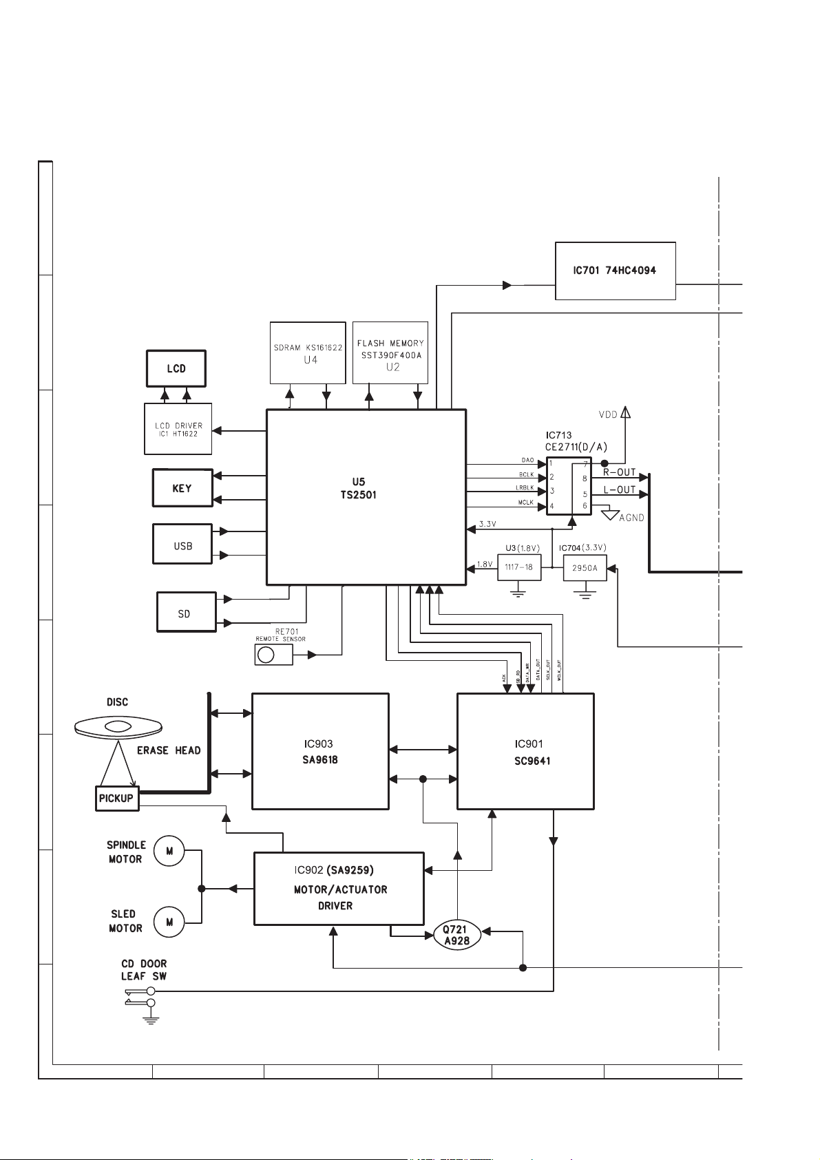
[1] Block Diagram .............................................3-1
CHAPTER 4. CIRCUIT DESCRIPTION
[1] Waveforms Of Servo Circuit ........................4-1
[2] Voltage.........................................................4-3
CHAPTER 5. CIRCUIT SCHEMATICS AND PARTS
LAYOUT
[1] Notes On Schematic Diagram .................. 5-1
[2] Types Of Transistor And LED ................... 5-1
[3] Wiring Side Of PWB/Schematic Diagram . 5-2
CHAPTER 6. FLOWCHART
[1] Troubleshooting ........................................ 6-1
CHAPTER 7. OTHERS
[1] Function Table Of IC................................. 7-1
[2] LCD Display............................................ 7-12
[3] Wiring Of Primary Supply Leads
(For U.K. Only)........................................ 7-13
PARTS GUIDE
SERVICE MANUAL
No. S7626XLUH4H//
Parts marked with " " are important for maintaining the safety of the set. Be sure to replace these parts with
specified ones for maintaining the safety and performance of the set.
CONTENTS
MICRO COMPONENT SYSTEM
MODEL
XL-UH4H Micro Component System consisting of
XL-UH4H (main unit) and CP-UH4H (speaker system).
•Note for users in U.K.
Recording and playback of any material may require
consent which SHARP is unable to give. Please refer
particularly to the provisions of Copyright Act 1956, the
Dramatic and Musical Performers Protection Act 1956, the
Performers Protection Acts 1963 and 1972 and to any
subsequent statutory enactments and orders.
• In the interests of user-safety (Required by safety regula-
tions in some countries) the set should be restored to its
original condition and only parts identical to those specified
be used.
XL-UH4H
This document has been published to be used for after
sales service only.
The contents are subject to change without notice.

XL-UH4H
– 2
PRECAUTIONS FOR USING LEAD-FREE SOLDER
1.Employing lead-free solder
Example:
Indicates lead-free solder of tin, silver and copper.
Lead-free wire solder for servicing
Ref No. Description
Parts No.
PWB-A1 92LUH400280029
92LUH401280000
PWB-A3
AUDIO
PWB-A2 92LUH400380003
CONTROL
RECTIFIER
PWB-B 92LUH400980000
CD
PWB-C 92LUH403280000
MCU
PWB-D 92LUH403080000
USB
"AUDIO, CONTROL, RECTIFIER, CD, MCU, USB PWB" of this model employs lead-free solder.
The LF symbol indicates lead-free solder, and is attached on the PWB and service manuals. The alphabetical
character following LF shows the type of lead-free solder.
2.
Using lead-free wire solder
When fixing the PWB soldered with the lead-free solder, apply lead-free wire solder. Repairing with conventional
lead wire solder may cause damage or accident due to cracks.
As the melting point of lead-free solder (Sn-Ag-Cu) is higher than the lead wire solder by 40 C, we recommend
you to use a dedicated soldering bit, if you are not familiar with how to obtain lead-free wire solder or soldering
bit, contact our service station or service branch in your area.
3.
Soldering
As the melting point of lead-free solder (Sn-Ag-Cu) is about 220 C which is higher than the conventional lead
solder by 40 C,and as it has poor solder wettability, you may be apt to keep the soldering bit in contact with the
PWB for extended period of time. However, since the land may be peeled of for the maximum heat-resistance
temperature of parts may be exceeded, remove the bit from the PWB as soon as you confirm the steady
soldering condition.
Lead-free solder contains more tin, and the end of the soldering bit may be easily corrected. Make sure to turn
on and off the power of the bit as required. If a different type of solder stays on the tip of the soldering bit, it is
alloyed with lead-free solder. Clean the bit after every use of it.
When the tip of the soldering bit is blackened during use, file it with steel wool or fine sand paper.
Be careful when replacing parts with polarity indication on the PWB silk.
i

XL-UH4H
1 – 3
CHAPTER 1.
GENERAL DESCRIPTION
[1] Safety Precaution For Service Manual
XL-UH4H XL-UH4H for U.K.
Laser Diode Properties
Material: AIGaAs
Wavelength: 790 nm
Emission Duration: continuous
Laser Output: max. 0.6 mW
Laser Diode Properties
Material: AIGaAs
Wavelength: 790 nm
Emission Duration: continuous
Laser Output: max. 0.6 mW
This product is classified as a CLASS 1 LASER PRODUCT.
Precaution to be taken when replacing and servicing the Laser Pickup.
1 – 1

XL-UH4H
1 – 4
[2] Important Service Notes (For U.K. Only)
Before returning the unit to the customer after completion of a repair or
adjustment it is necessary for the following withstand voltage test to be
applied to ensure the unit is safe for the customer to use.
Setting of Withstanding Voltage Tester and set.
[3] Specifications
Set name set value
Withstanding Voltage Tester
Test voltage 4,240 VPEAK
3,000 VRMS
Set time 6 secs
Set current (Cutoff current) 4 mA
Unit
Judgment
OK: The “GOOD” lamp lights.
NG: The “NG” lamp lights and the buzzer sounds.
PROBE
AC OUT UNIT
SHORT-CIRCUIT
AC POWER
SUPPLY CORD
CONNECT THE PROBE
TO GND OF CHASSIS
SCREW
WITHSTANDING
VOLTAGE TESTER
FOR A COMPLETE DESCRIPTION OF THE OPERATION OF THIS UNIT, PLEASE REFER TO THE OPERATION MANUAL.
General
Amplifier
CD player
Tuner
USB/SD
Power source AC 230 V, 50 Hz
Power
consumption Power on: 26 W
Power stand-by: 0.6 W(*)
Dimensions Width: 144 mm (5-11/16")
Height: 210 mm (8-5/16")
Depth: 239 mm (9-7/16")
Weight 2.3 kg (5.1 lbs.)
( * )This power consumption value is obtained when the unit is in the
power stand-by mode.
Output power PMPO: 160 W
MPO: 30 W (15 W + 15 W) (DIN 45 324)
RMS: 16 W (8 W + 8 W) (DIN 45 324)
RMS: 12 W (6 W + 6 W) (DIN 45 500)
Output terminals Speakers: 4 ohms
Headphones: 16 - 50 ohms
(recommended: 32 ohms)
Type Compact disc player
Signal readout Non-contact, 3-beam semi conductor laser
pickup
D/A converter 1-bit D/A converter
Frequency
response 20 - 20,000Hz
Dynamic range 90 dB (1kHz)
Frequency range FM: 87.5 - 108MHz
AM: 522 - 1,620kHz
Class Mass storage class
Support file MP3/WMA (do not support DRM file)
Format support FAT 16 or FAT 32
Bitrate support MP3 (32 ~ 320 kbps)
WMA (64 ~ 160 kbps)
Other MP3 ID3 - tag only supports version 1.x
USB supports version 2.0
Speaker
Type 2-way type speaker system
5 cm (2") tweeter
10 cm (4") woofer
Rated input power 8 W
Impedance 4 ohms
Dimensions
Weight
Width: 135 mm (5-5/16")
Height: 242 mm (9-1/2")
Depth: 205 mm (8-1/16")
1.8 kg (4 lbs.)/each
Maximum input
power 16 W
1 – 2

XL-UH4H
1 – 5
Front panel
1.CD Door
2.On/Stand-by Button
3.Timer Indicator
4.Memory/Disp Button
5.Disc or USB or SD Stop Button
6.Remote Sensor
7.Disc Track Down or Fast Reverse, Tuner Preset Down,
Time Down Button
8.Headphone Socket
9.CD Play/Pause Button
10.Tuning Down/Folder Down Button
11.USB/SD Play/Pause Button
12.USB/SD Terminal
13.Clock/Timer Button
14.Sleep Button
15.Volume Control
16.Disc Track Up or Fast Forward, Tuner Preset Up,
Time Up Button
17.Tuner (Band) Button
18.Tuning Up/Folder Up Button
Display
1.Memory Indicator
2.MP3/WMA Folder Indicator
3.Disc or USB or SD Repeat Play Indicator
4.Random Indicator
5.
6.
7.
MP3/WMA Track Indicator
8.
WMA Indicator
9.
MP3 Indicator
10.
CD Indicator
11.
Disc or USB or SD Pause Indicator
12.
Disc or USB or SD Play Indicator
13.
USB Indicator
14.
SD Indicator
15.
RDS Indicator
16.
Timer Play Indicator
17.
Sleep Indicator
18.
Equaliser (ROCK, CLASSIC, POPS, JAZZ) Indicator
19.
Extra Bass Indicator
FM Stereo Mode Indicator
FM Stereo Receiving Indicator
[4] Names Of Parts
MEMORY
SLEEP
TRACK
ROCK CLASSIC POPS JAZZ
X BASS ST
W
M
A
M
P
3
USB RDS
kHz
MHz
FOLDER 1 RANDOM
CD
TRACK
W
M
A
M
P
3
USB RDS
CD
1
5 6 7 8 9 10 11 12
243
15 16 17 1819
14
13
1 – 3

XL-UH4H
1 – 6
Remote control
1.Remote Control Transmitter
2.On/Stand-by Button
3.Tuning Up/Folder Up Button
4.Tuning Down/Folder Down Button
5.RDS ASPM/PTY Button
6.RDS Display Button
7.Disc Direct Search Buttons
8.Sleep Button
9.Clock/Timer Button
10.Random Button
11.Memory/Disp Button
12.Volume Up and Down Buttons
13.Repeat Button
14.Extra Bass Button
15.Equaliser Button
16.CD Play and Pause Button
17.USB/SD Play and Pause Button
18.Tuner (Band) Button
19.Disc Track Down or Fast Reverse, Tuner Preset Down,
Time Down Button
20.Disc Track Up or Fast Forward, Tuner Preset Up,
Time Up Button
21.Disc or USB or SD Stop Button
23
4
1
Rear panel
1. AM Loop Aerial Terminal
2. FM 75 Ohms Aerial Socket
3. Speaker Terminals
4. AC Power Lead
Speaker system
1.Tweeter
2.Woofer
3.Bass Reflex Duct
4.Speaker Wire
2
3
4
5
6
7
8
9
10
11
12
13
14
15
1
16 17 18
19 20 21
3
4
1
2
1 – 4

XL-UH4H
2 – 1
CD-ES700/CD-ES77CD-ES700/CD-ES77Service ManualCD-ES700/CD-ES77MarketE
CHAPTER 3.
[1] Caution on disassembly
Caution on Disassembly
Follow the below-mentioned notes when disassembling the unit and reassembling it, to keep it safe and ensure excel-
lent performance:
1. Take cassette tape and compact disc out of the unit.
2. Be sure to remove the power supply plug from the wall outlet before starting to disassemble the unit.
3. Take off nylon bands or wire holders where they need to be removed when disassembling the unit. After servicing the
unit, be sure to rearrange the leads where they were before disassembling.
CHAPTER 2. MECHANISM BLOCKS
STEP REMOVAL PROCEDURE FIGURE
1 Rear Cabinet
1. Screw……….……………….
(A1) X 6 1
2. Screw……….……………….
(A2) X 4 1
3. Socket………………..…….
(A3) X 1 7
2 Top Cabinet
1. Screw…………..…………..
(B1) X 2 2
2. Socket……..……………….
(B2) X 3
3. Flat Cable……..……………….
(B3) X 1
3 AUDIO PWB
1. Screw………………..………
(C1) X 2 3
2. Socket……..……………….
(C2) X 3
4 MCU PWB
1. Socket…………..…………..
(D1) X 1 3
5 CD PWB
1. Screw…………..…………..
(E1) X 4 4
6 CONTROL PWB
1. Screw…….…………..……..
(F1) X 8 5
7 USB PWB
1. Screw………………...…….
(G1) X 2 6
8 RECTIFIER PWB
1. Screw…………..………….
(H1) X 2 7
2. Socket………………..……
(H2) X 3

XL-UH4H
3 – 1
CHAPTER 3. DIAGRAM
[1] Block Diagram
A
B
C
D
E
F
G
H
123456
Figure 1: BLOCK DIAGRAM (1/2)

XL-UH4H
3 – 2
78 9 10 11 12
Figure 2: BLOCK DIAGRAM (2/2)

XL-UH4H
4 – 1
CHAPTER 4.
CIRCUIT DESCRIPTION
[1] Waveform Of Servo Circuit
< Z1 : 2.5M > < Z1 :1 00K >
< Z1 : 2M > < Z1 : 2M >
< Z1 : 25K >
CH 4
Display500ms/div
100ms/div 1s/div
20µs/div
Freq(C1) *****
Position
Coupling
DC1M
Probe
10:1
Offset
0:32 V
Bandwidth
Edge CH4
Auto
0.50 V
Edge CH4
Auto
0.50 V
CH1 10:1
1.00 V/div
DC Full
Edge CH4
Auto
0.50 V
CH1 10:1
2.00 V/div
DC Full
CH1 10:1
1.00 V/div
DC Full
Edge CH4
Auto
0.50 V
CH1 10:1
2.00 V/div
DC Full
CH2 10:1
2.00 V/div
DC Full
CH3 10:1
2.00 V/div
DC Full
CH4 10:1
2.00 V/div
DC Full
Edge CH4
Auto
0.001 kV
CH1 10:1
5.00 V/div
DC Full
CH2 10:1
5.00 V/div
DC Full
CH3 10:1
5.00 V/div
DC Full
Full
ONOFF
-0.20div
CH 4
Display
Position
Coupling
DC1M
Probe
10:1
Offset
Bandwidth
Freq(C1)
FR-A(C4) Freq(C2) 50.00000kHz
40.00000kHz
43.75492kHz Full
ONOFF
- 3.00div
MEASURE
Mode
Item Setup
Delay Setup
1Cycle Mode
OFF
Time Range1
Time Range2
ON
ON
1.57000div
1.77000div
Freq (C1)
50.00000kHz
0.2vCH1 A>0.2µs
˜
0:82 V
1
IC902 19
2
IC901 24
6
IC901 12
2
IC901 24
1
IC902 19
4
IC902 24
3
IC902 4
5
IC902 10
9
IC901 21
8
IC901 22
7
IC901 23

XL-UH4H
4 – 2
13
IC901 31
12
IC901 33
11
IC901 32
10
IC901 43
3
IC902 4
14
IC901 64
< Z1 : 2.5M >
< Z1 : 2M > 1s/div
500ms/div
CH1 10:1
2.00 V/div
DC Full
CH1 10:1
2.00 V/div
DC Full
Edge CH4
Auto
0.50 V
CH1 10:1
5.00 V/div
DC Full
CH2 10:1
2.00 V/div
DC Full
CH3 10:1
2.00 V/div
DC Full
CH4 10:1
2.00 V/div
DC Full
Edge CH4
Auto
0.50 V
Freq (C1)
22.22222kHz
Freq (C1)
P1sN (C4)
FR-A (C4)
31.25000kHz
5.891783kHz
1133

XL-UH4H
4 – 3
[2] IC Voltage
PIN PIN PIN PIN PIN PIN
NO NO NO NO NO NO
1 3.10 1 3.26 1 0.00 1 0.00 33 3.63 1 3.42
2 0.11 2 2.72 2 0.00 2 5.13 34 4.93 2 3.42
3 0.15 3 2.72 3 0.00 3 2.58 35 4.93 3 2.53
4 0.15 4 0.00 4 0.12 4 2.58 36 4.93 4 2.56
5 0.15 5 2.72 5 1.66 5 2.58 37 4.93 5 6.86
6 0.19 6 2.72 6 0.00 6 2.58 38 4.93 6 5.22
7 3.07 7 3.26 7 3.33 7 2.45 39 4.93 7 3.80
8 0.17 8 2.80 8 1.65 8 2.45 40 4.93 8 0.00
9 0.00 9 2.72 9 2.63 41 4.93 9 0.05
10 NC 10 0.00 10 4.29 42 0.00 10 2.55
11 3.26 11 2.75 11
12 2.61 43 4.81 11 3.45
12 0.00 12 2.83 PIN 2.61 44 5.13 12 0.02
13 NC 13 3.26 NO 13 2.61 45 0.00 13 0.00
14 0.00 14 2.90 Input 3.27 14 2.61 46 5.13 14 0.00
15 3.27 15 3.26 GND 0.00 15 0.00 47 2.55 15 3.46
16 0.00 16 3.10
Output
1.79 16 5.15 48 2.59 16 3.30
17 0.00 17 3.07 17 2.43 49 2.56 17 3.40
18 3.08 18 3.26 18 1.16 50 2.56 18 3.40
19 0.17 19 0.18 19
20 0.00 51 2.55 19 2.17
20 0.17 20 0.18 PIN 0.03 52 2.52 20 7.54
21 0.17 21 0.18 NO 21 2.27 53 2.52 21 7.54
22 0.22 22 0.18 VCC 3.27 22 2.03 54 2.52 22 7.54
23 0.17 23 0.00 GND 0.00 23 3.79 55 0.00 23 2.20
24 3.27 24 0.00 Reset 3.27 24 4.96 56 4.98 24 2.20
25 0.00 25 3.26 25 0.03 57 0.00 25 2.20
26 2.90 26 0.00 26 0.00 58 2.52 26 3.50
27 0.00 27 0.16 27
28 0.00 59 5.13 27 3.45
28 2.89 28 0.16 PIN 4.97 60 5.13 28 0.00
29 2.72 29 0.16 NO 29 0.02 61 0.00
30 2.89 30 3.08 Input 5.04 30 1.54 62 2.57
31 2.69 31 0.18 GND 0.00 31 3.26 63 5.01
32 2.82 32 3.06
Output
3.27 32 3.26 64 0.00 PIN
33 2.75 33 NC NO
34 2.75 34 3.26 1 0.00
35 3.27 35 1.75 2 0.00
36 2.80 36 2.90 PIN PIN PIN 3 0.00
37 3.26 37 NC NO NO NO 4 0.00
38 2.80 38 3.26 1 3.25 1 0.00 1 0.00 5 0.00
39 2.60 39 2.87 2 4.94 2 0.00 2 0.00 6 0.00
40 2.72 40 2.87 3 0.00 3 0.00 3 0.00 7 0.00
41 2.95 41 0.00 4 2.63 4 0.00 4 0.00 8 0.01
42 2.75 42 2.71 5 2.63 5 0.00 5 0.00 9 0.00
43 2.95 43 2.71 6 0.00 6 0.00 6 0.00
44 2.83 44 3.26 7 2.63 7 0.00 7 0.00
45 2.94 45 3.14 8 0.00 8 0.00 8 0.01
46 0.00 46 3.14 9 0.00 9 0.00 9 0.00 PIN
47 3.09 47 0.00 10 2.63 10 0.00 10 0.00 NO
48 2.96 48 2.95 11 2.66 11 0.00 11 0.00 E 0.00
49 2.95 12 2.59 12 0.00 12 0.00 B 0.00
50 0.00 13 2.73 13 0.00 C 0.00
14 2.51 14 0.00
15 0.13 15 0.00
16 5.19 16 0.00 PIN
NO PIN
E 4.99 NO
B 5.65 E 0.00
C 8.32 B 0.00
C 0.00
9014
VOLTAGE
Q316
8050
VOLTAGE
Q301
9014
VOLTAGE
Q302
LA-4227
VOLTAGE
U301
LA-4227
VOLTAGE
U716
2950A
VOLTAGE
U903
SA9618
VOLTAGE
U501
TC-4052
VOLTAGE
809R
VOLTAGE VOLTAGE
SC9641
U714
SA9259
VOLTAGE
U301
U711 U712
16161A U713 IC901
1117-18
VOLTAGE
U715
IC902
CE2711
VOLTAGEVOLTAGE VOLTAGE
SST39VF800A
VOLTAGE

XL-UH4H
4 – 4
PIN PIN PIN PIN PIN PIN
NO NO NO NO NO NO
E 0.00 E 0.00 E 5.10 E 7.66 E 0.00 E 7.81
B 0.64 B 0.64 B 5.70 B 8.33 B 0.00 B 5.06
C 0.00 C 0.00 C 7.37 C 11.10 C 0.00 C 7.14
PIN PIN PIN PIN PIN PIN
NO NO NO NO NO NO
E 0.00 E 0.00 E 5.19 E 0.00 E 0.00 E 7.51
B 0.00 B 0.00 B 4.94 B 0.00 B 0.67 B 6.75
C 0.00 C 0.00 C 0.00 C 4.81 C 0.00 C 7.42
PIN PIN PIN PIN PIN PIN
NO NO NO NO NO NO
E 0.00 E 0.00 1 0.00 33 0.20 65 0.00 97 0.00
B 0.00 B 0.00 2 3.24 34 0.12 66 0.13 98 0.01
C 0.00 C 0.00 3 2.77 35 3.09 67 0.00 99 NC
4 2.71 36 1.61 68 0.00 100 NC
5 2.80 37 0.00 69 NC 101 NC
6 2.57 38 0.00 70 NC 102 NC
7 1.79 39 0.00 71 1.79 103 NC
8 0.00 40 0.00 72 3.27 104 0.12
9 2.93 41 1.79 73 3.27 105 1.83
10 2.67 42 2.87 74 0.87 106 1.83
11 2.68 43 2.88 75 0.87 107 1.83
12 2.56 44 1.68 76 3.27 108 3.27
13 2.94 45 0.00 77 1.79 109 1.79
14 0.00 46 2.78 78 1.00 110 0.00
15 2.92 47 0.29 79 0.00 111 3.27
16 3.26 48 3.25 80 0.00 112 3.27
17 0.00 49 3.61 81 3.27 113 3.27
18 0.17 50 2.78 82 3.27 114 1.30
19 0.17 51 0.00 83 NC 115 3.27
20 0.23 52 3.24 84 3.27 116 0.00
21 0.18 53 0.00 85 0.00 117 0.00
22 0.17 54 0.00 86 0.00 118 NC
23 0.17 55 0.00 87 1.79 119 1.79
24 1.79 56 3.26 88 0.00 120 0.00
25 0.00 57 0.09 89 3.27 121 NC
26 3.08 58 3.26 90 0.00 122 NC
27 0.17 59 2.89 91 0.00 123 0.00
28 3.05 60 NC 92 3.25 124 NC
29 2.68 61 NC 93 NC 125 2.76
30 0.21 62 0.00 94 NC 126 2.76
31 0.14 63 0.00 95 0.00 127 2.76
32 0.00 64 3.27 96 0.00 128 2.76
VOLTAGE VOLTAGE
9014 9014
Q201 Q202
A928
VOLTAGE VOLTAGE VOLTAGE VOLTAGE VOLTAGE VOLTAGE
8050 9014 8550 8050
Q910
S8050
VOLTAGE
Q1101
2061 Q203
9014
Q313 Q314
9014 Q315
9014
Q802 Q801
VOLTAGE VOLTAGEVOLTAGE VOLTAGEVOLTAGE
Q912 Q913 Q720
764
VOLTAGE VOLTAGE
U710
TS2501
Q721
9014
VOLTAGE VOLTAGE

XL-UH4H
4 – 5
-MEMO-

XL-UH4H
5 – 1
CHAPTER 5. CIRCUIT SCHEMATICS AND PARTS LAYOUT
[1] Notes On Schematic Diagram
[2] Types Of Transistor And LED
•Resistor:
To differentiate the units of resistors, such symbol as K and M are
used: the symbol K means 1000 ohm and the symbol M means
1000 kohm and the resistor without any symbol is ohm-type resis-
tor. Besides, the one with “Fusible” is a fuse type.
• Capacitor:
To indicate the unit of capacitor, a symbol P is used: this symbol P
means pico-farad and the unit of the capacitor without such a sym-
bol is microfarad. As to electrolytic capacitor, the expression
"capacitance/withstand voltage is used".
(CH), (TH), (RH), (UJ): Temperature compensation
(ML): Mylar type
(P.P.): Polypropylene type
• Schematic diagram and Wiring Side of P.W.Board for this model are
subject to change for improvement without prior notice.
• The indicated voltage in each section is the one measured by Digi-
tal Multimeter between such a section and the chassis with no sig-
nal given.
1. In the tuner section,
indicates AM
indicates FM stereo
2. In the CD section, the CD is stopped.
• Parts marked with “ “ ( ) are important for main-
taining the safety of the set. Be sure to replace these parts with
specified ones for maintaining the safety and performance of the
set.
REF. NO DESCRIPTION POSITION
SW701 DISC4 ON—OFF
SW702 DISC5 ON—OFF
SW703 OPEN/CLOSE ON—OFF
SW704 DISC1 ON—OFF
SW705 DISC2 ON—OFF
SW706 DISC3 ON—OFF
SW707 POWER ON/STAND-BY ON—OFF
SW708 PLAY/PAUSE ON—OFF
SW709 STOP
SW710 VIDEO/AUX/USB
SW711 TUNER (BAND)
SW712 CD
VR701 VOLUME
ON—OFF
ON—OFF
ON—OFF
ON—OFF
MAX —MIN
HY4C
HY3C
B
(3)
E
(1)
C
(2)
TOP
VIEW
TOP VIEW
A928A
B764
9015C
9014C
S8550
S8050
VIEW
FRONT
ECB
(S)(G)(D)
VIEW
FRONT
ECB
(1)(2)(3) 1N4001
1N4148
1N5401
FRONT
VIEW
92L22708050021SD1936 92L22708050001

XL-UH4H
5 – 2
[3] Wiring Side Of PWB/Schematic Diagram
Figure 6-1: MAIN SCHEMATIC DIAGRAM AUDIO (1/2)
A
B
C
D
E
F
G
H
123456

XL-UH4H
5 – 3
Figure 6-2: MAIN SCHEMATIC DIAGRAM AUDIO (2/2)
78 9 10 11 12

XL-UH4H
5 – 4
A
B
C
D
E
F
G
H
123456
Figure 5-3: MAIN SCHEMATIC DIAGRAM CONTROL & USB

XL-UH4H
5 – 5
A
B
C
D
E
F
G
H
123456
Figure 5-4: MAIN SCHEMATIC DIAGRAM RECTIFIER

XL-UH4H
5 – 6
Figure 6-5: CD SCHEMATIC DIAGRAM (1/2)
Other manuals for XL-UH4H
2
Table of contents
Other Sharp Stereo System manuals

Sharp
Sharp MD-X8 User manual

Sharp
Sharp XL-DK227NH User manual

Sharp
Sharp SD-EX220H User manual

Sharp
Sharp CD-BA2010H User manual

Sharp
Sharp CD-C621H User manual

Sharp
Sharp CD-MPS777H User manual

Sharp
Sharp QT-CD161H User manual

Sharp
Sharp CD-BK133W User manual

Sharp
Sharp WF-2000W User manual

Sharp
Sharp XL-DAB227NH User manual

Sharp
Sharp CD-BA150 User manual

Sharp
Sharp XL-UH2080H User manual

Sharp
Sharp CD-SW200H User manual

Sharp
Sharp CD-C471H User manual

Sharp
Sharp SD-NX10 User manual

Sharp
Sharp CD-BA2000H User manual

Sharp
Sharp QT-V5E User manual

Sharp
Sharp XL-30V User manual

Sharp
Sharp CD-BK300W User manual

Sharp
Sharp GBOXS0072AWM1 User manual