R,EMOVAL AND REASSEMBLY OF
5.
CASSETTE HOUSING CONTROL ASSEMBLY
0
1.
2.
3.
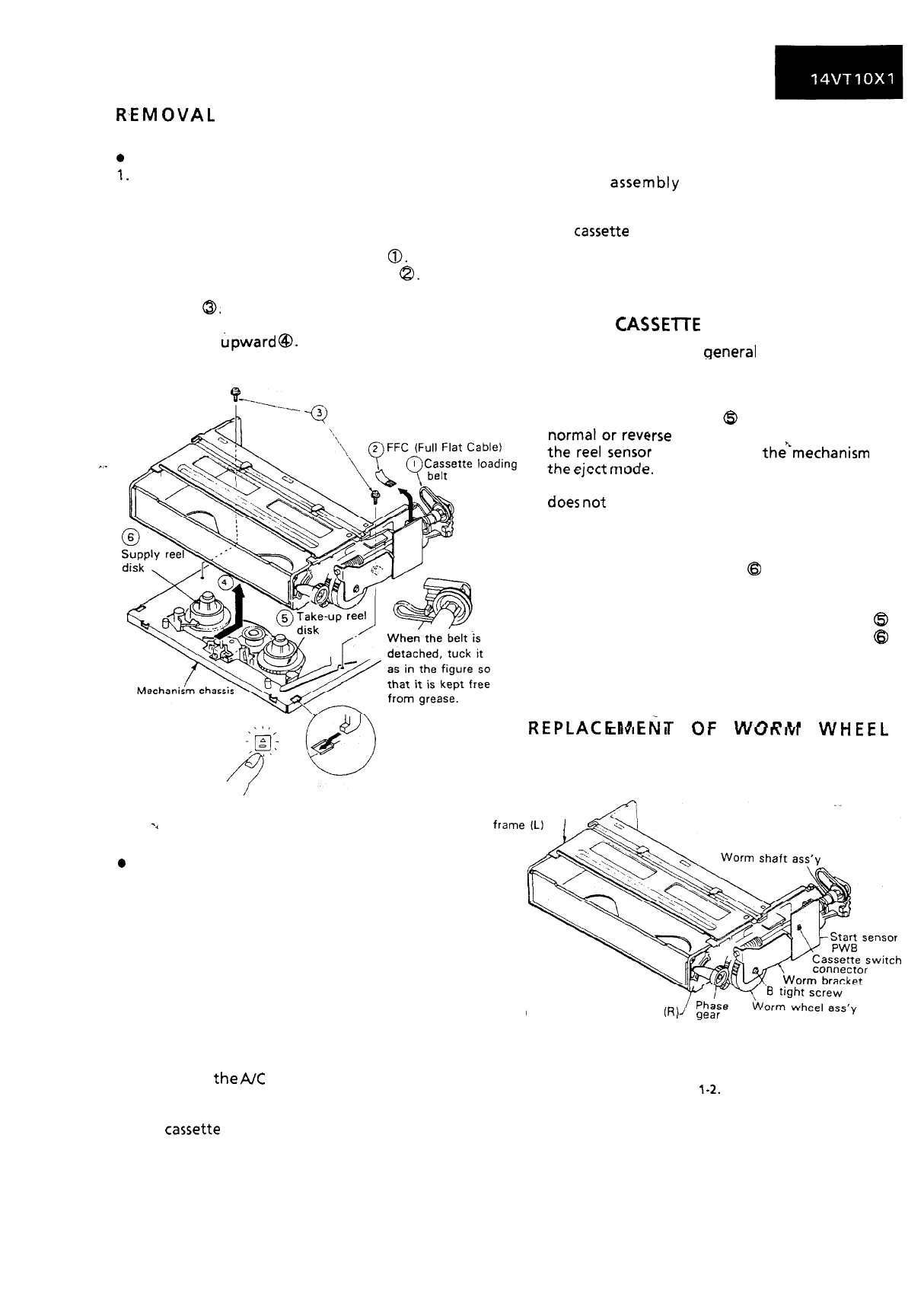
Removal
Set the cassette ejected condition in the cassette
eject mode.
6.
Unplug the recorder from the main source.
Follow the procedures below in the specified
order.
a) Remove the cassette loading belt
0.
b) Disconnect the FFC (full Flat Cable)
8.
c) Remove the cassette housing installation
Place the unit in the eject mode in removal or
reassembly of the cassette housing control
assembly.
Load the cassette once onto the cassette housing
control
assembly
after reassembly. (If the
cassette housing control assembly normally
operates after this, the phases of mechanism and
the
cassette
controller are accurately adjusted
after ejection.)
screws
0.
d) Slide and pull out the cassette housing control
MECHANICAL OPERATION CHECK
WITHOUT
CASSElTE
assembly
upward
@I.
When power is on, the general operations of the
~-I-
/==h
-
_
Q
3
Cassette housing
setscrew
mechanism can be checked without a cassette.
Note the following points.
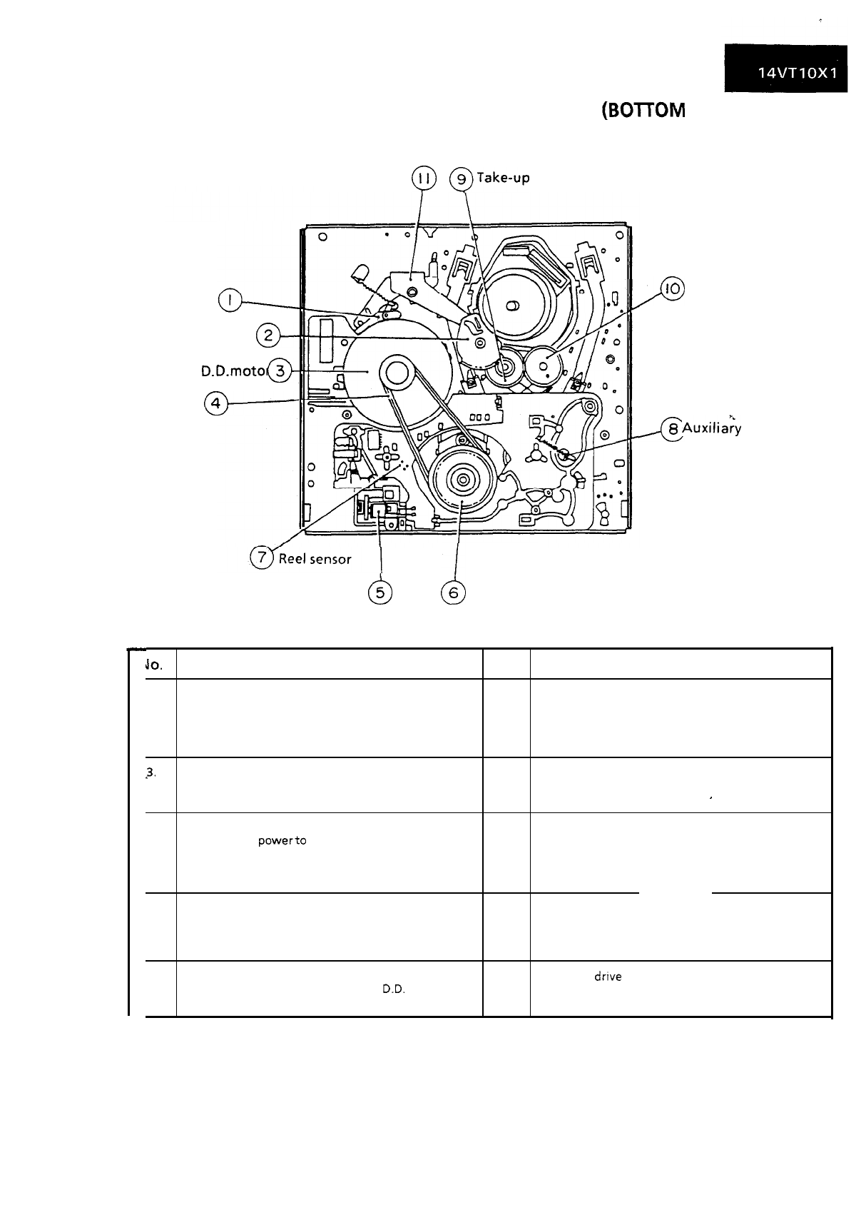
1. Check video search rewind and rewind, rotating
the take-up reel disk
@
by hand (in either
!rse
direction). If it is not rotated,
*
works to shift
the’Lmechanism
to
C1I.c
G,\-LC
,,,““d.
2. When the stop button is pressed, the mechanism
does
not
stop at a normal stop position. It shifts
to the eject mode and stops.
3. When the stop button is pressed in the playback,
video search rewind, and video search forward
modes, the supply reel disk
0
keeps on rotating
for several seconds for elimination of tape slack
in the course of shifting to the eject mode. In
such a case, rotate the take-up reel disk
@
somewhat by hand, and the supply reel disk
0
stops, which can reduce the working time.
Insert the tab of
the cassette hosing
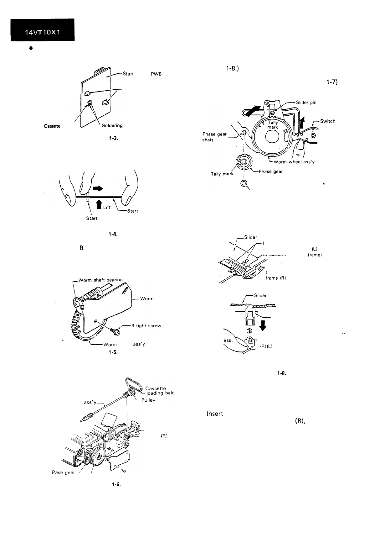
REpLAC~liACil’
fiC
\Il,h”l”
\“,,,rrl
,
E
IVI
c
IY
I
u
r
vv
u
n
WI
VvnrcL
control assembly to
ASSEMB
LY
the mechanism chassis.
-.
Figure 1-l.
0
Reassembly
1. Before installation of the cassette housing
control assembly, place the unit in the stop mode
with the power on, then unplug the power cord.
(The main body is placed in the eject mode.)
2. Follow the procedures for removal in the reverse
order.
Notes:
1. Be sure to unplug the power cord in removal and
reassembly.
2. Keep the cassette loading belt free from grease.
In case of its adhesion, clean the belt.
3. In using a magnet screw driver, be sure to keep it
away from
the
A/C
head, FE (Full Erase) head, or
the drum.
4. In removal and reassembly, take care not to hit
the
cassette
housing control assembly or tools
against the guide pin, drum, or the like
thereabout.
Cassette housing
Cassette housing frame
(R)
Figure
l-2.
11