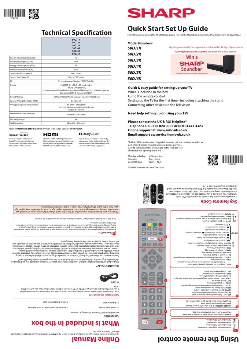
Sharp 4T-C60AH1X User manual

SERVICE MANUAL
Ver 1
No. SZ8M224T-C6070AH1X
LED BACKLIGHT TV
:4T-C60AH1X
MODEL
Parts marked with " " are important for maintaining the safety of the set. Be sure to replace these parts with specified ones for maintaining the
safety and performance of the set.
This document has been published to be used for
after sales service only.
The contents are subject to change without notice.
SAFETY PRECAUTION
SAFETY PRECAUTION......................................i
CHAPTER 1. OUTLINE
[1] MAJOR SERVICES PARTS........................... 1-1
CHAPTER 2. SPECIFICATION
[1] SPECIFICATION............................................ 2-1
CHAPTER 3. OPERATION
[1] OPERATION .................................................. 3-1
CHAPTER 4. DIMENSION
[1] DIMENSION................................................... 4-1
CHAPTER 5. ADJUSTMENT
[1] ADJUSTMENT ............................................... 5-1
CHAPTER 6. TROUBLESHOOTING
[1] TROUBLESHOOTING ................................... 6-1
CHAPTER 7. DESCRIPTION OF SCHEMATIC DIA-
GRAM
[1] DESCRIPTION OF SCHEMATIC DIA-
GRAM ............................................................ 7-1
CHAPTER 8. SYSTEM BLOCK DIAGRAM
[1] SYSTEM BLOCK DIAGRAM ......................... 8-1
Parts Guide
TopPage
CONTENTS
:4T-C70AH1X

4T-C6070AH1X
i
SAFETY PRECAUTION
SAFETY PRECAUTION
IMPORTANTSERVICE SAFETYPRECAUTION
WARNING
1. For continued safety, no modification of any circuit should be
attempted.
2. Disconnect AC power before servicing.
BEFORE RETURNING THE RECEIVER (Fire &
Shock Hazard)
Before returning the receiver to the user, perform the following
safety checks:
3. Inspect all lead dress to make certain that leads are not pinched,
and check that hardware is not lodged between the chassis and
other metal parts in the receiver.
4. Inspect all protective devices such as non-metallic control knobs,
insulation materials, cabinet backs, adjustment and compartment
covers or shields, isolation resistor-capacitor networks, mechanical
insulators, etc.
5. To be sure that no shock hazard exists, check for leakage current in
the following manner.
• Plug the AC cord directly into a 110-240 volt AC outlet.
• Using two clip leads, connect a 1.5k ohm, 10 watt resistor paral-
leled by a 0.15 F capacitor in series with all exposed metal cabinet
parts and a known earth ground, such as electrical conduit or elec-
trical ground connected to an earth ground.
• Use an AC voltmeter having with 5000 ohm per volt, or higher, sen-
sitivity or measure the AC voltage drop across the resistor.
• Connect the resistor connection to all exposed metal parts having a
return to the chassis (antenna, metal cabinet, screw heads, knobs
and control shafts, escutcheon, etc.) and measure the AC voltage
drop across the resistor.
All checks must be repeated with the AC cord plug connection
reversed. (If necessary, a nonpolarized adaptor plug must be used
only for the purpose of completing these checks.)
Any reading of 0.74 Vrms (this corresponds to 0.5 mA rms AC.) or
more is excessive and indicates a potential shock hazard which
must be corrected before returning the monitor to the owner.
///////////////////////////////////////////////////////////////////////////////////////////////////////////////////////////////
SAFETYNOTICE
Many electrical and mechanical parts in LCD colour television have
special safety-related characteristics.
These characteristics are often not evident from visual inspection, nor
can protection afforded by them be necessarily increased by using
replacement components rated for higher voltage, wattage, etc.
Replacement parts which have these special safety characteristics are
identified in this manual; electrical components having such features
are identified by " " and shaded areas in the Replacement Parts List
and Schematic Diagrams.
For continued protection, replacement parts must be identical to those
used in the original circuit.
The use of a substitute replacement parts which do not have the same
safety characteristics as the factory recommended replacement parts
shown in this service manual, may create shock, fire or other hazards.
///////////////////////////////////////////////////////////////////////////////////////////////////////////////////////////////
Service work should be performed only by qualified service technicians who are thoroughly familiar with all safety checks and the
servicing guidelines which follow:
DVM
AC SCALE
1.5k ohm
10W
TO EXPOSED
METAL PARTS CONNECT TO
KNOWN EARTH
GROUND
0.15
µ
F
TEST PROBE
SAFETY PRECAUTION
4T-C6070AH1X
ii
PRECAUTIONS FOR USING LEAD-FREE SOLDER
Employinglead-free solder
• “PWBs” of this model employs lead-free solder. The LF symbol indicates lead-free solder, and is attached on the PWBs and service manuals. The
alphabetical character following LF shows the type oflead-free solder.
Example:
Usinglead-freewiresolder
• When fixing the PWB soldered with the lead-free solder, apply lead-free wire solder. Repairing with conventional lead wire solder may cause dam-
age or accident due to cracks.
As the melting point oflead-free solder (Sn-Ag-Cu) is higher than the lead wire solder by 40 C, we recommend you to use a dedicated soldering
bit, if you are not familiar with how to obtain lead-free wire solder or soldering bit, contact our service station or service branch in your area.
Soldering
• As the melting point oflead-free solder (Sn-Ag-Cu) is about 220 C which is higher than the conventional lead solder by 40 C, and as it has poor
solder wettability, you may be apt to keep the soldering bit in contact with the PWB for extended period of time. However, Since the land may be
peeled off or the maximum heat-resistance temperature of parts may be exceeded, remove the bit from the PWB as soon as you confirm the
steady soldering condition.
Lead-free solder contains more tin, and the end of the soldering bit may be easily corroded. Make sure to turn on and off the power of the bit as
required.
If a different type of solder stays on the tip of the soldering bit, it is alloyed with lead-free solder. Clean the bit after every use ofit.
When the tip of the soldering bit is blackened during use, file it with steel wool or fine sandpaper.
• Be careful when replacing parts with polarity indication on the PWB silk.
Lead-free wire solder for servicing
Indicates lead-free solder of tin, silver and copper. Indicates lead-free solder of tin, silver and copper.
PARTSCODEPRICE
RANK
PART
DELIVERY DESCRIPTION
ZHNDAi123250E BL J 0.3mm 250g (1roll)
ZHNDAi126500E BK J 0.6mm 500g (1roll)
ZHNDAi12801KE BM J 1.0mm 1kg (1roll)

4T-C6070AH1X
1 – 1
CHAPTER 1. OUTLINE
[1] MAJOR SERVICES PARTS
OUTLINE
MAJOR SERVICE PARTS
No Part Code Description Note
NDKEYMG924FM01 MAIN UNIT (GENERAL)
NRUNTKB748WJQZ POWER UNIT
NRUNTKB731WJQZ KEY UNIT
NDUNTKG498FM02 LED/ IR UNIT
NRUNTKB751WJQZ WIFI + BT UNIT
4T-C70AH1X
NDKEYMG924FM01 MAIN UNIT (GENERAL)
NRUNTKB749WJQZ POWER UNIT
NRUNTKB732WJQZ KEY UNIT
NDUNTKG498FM02 LED/ IR UNIT
NRUNTKB707WJQZ WIFI + BT UNIT
NKSETLA751WJ20 60" LCD PANEL MODULE UNIT
NKSETLA752WJ20 70" LCD PANEL MODULE UNIT
PRINTED WIRING BOARD ASSEMBLIES
LCD PANEL MODULE UNIT
4T-C60AH1X
PRINTED WIRING BOARD ASSEMBLIES

4T-C6070AH1X
2 – 1
CHAPTER 2. SPECIFICATION
[1] SPECIFICATION
Model
Item X1HA07C-T4X1HA06C-T4
mc771mc351lenapDCL
Resolution 8,294,400 pixels (3840 g2160)
06LAP/34.4CSTN/85.3CSTN/MACES/LAPmetsysruolocoediV
TV function TV-
standard
Analogue PAL: B/G, D/K, I SECAM: B/G, D/K, K/K1 NTSC: M
Digital DVB-T / DVB-T2
Receiving
channel
VHF/UHF 44.25—863.25 MHz
CATV S1—S41 ch (including Hyperband)
TV-tuning system Auto Preset 99 ch
STEREO/BILINGUAL NICAM: B/G, I, D/K A2 stereo: B/G MTS: M
Audio amplifier
10 W g2
Terminals ANT (Antenna input) UHF/VHF 75 qDIN type
SERVICE ONLY 3.5 mm jack
INPUT 1 (ARC) HDMI HDMI (HDMI input), ARC
INPUT 2 HDMI HDMI (HDMI input)
INPUT 3 AUDIO in, VIDEO in
AUDIO OUT AUDIO out, Headphone ( 3.5 mm stereo)
)tuptuoA5.1V5CD(BSUBSU
ETHERNET
(10/100 BASE-T)
Network connector
ilpmiS/hsilgnEegaugnalDSO fied Chinese/Arabic/French/Portuguese/Russian/
Persian/Thai/Vietnamese/Indonesia/Hebrew/Hindi/Malay
zH06/05,V042—011CAtnemeriuqerrewoP
)ybdnatSW6.0(W022)ybdnatSW6.0(W581noitpmusnocrewoP
Dimensions without stand
1359 (W) g790 (H) g50 (D) mm 1563 (W) g904 (H) g52 (D) mm
with stand
1359 (W) g852 (H) g257 (D) mm
1563 (W) g978 (H) g334 (D) mm
Weight without stand (with stand) 20.8 kg (21.5 kg) 31.0 kg (32.0 kg)
C°04+otC°0erutarepmetgnitarepO
•As a part of policy of continuous improvement, SHARP reserves the right to make design and specification changes
for product improvement without prior notice. The performance specification figures indicated are nominal values of
production units. There may be some deviations from these values in individual units.
•Specification may differ depending on the selected country.
CAUTION
•Installing the Liquid Crystal Television requires special skill that should only be performed by qualified service
personnel. Customers should not attempt to do the work themselves. SHARP bears no responsibility for improper
mounting or mounting that results in accident or injury.
•Carefully read the instructions that come with the bracket before beginning work.
Specifications

4T-C6070AH1X
3 – 1
CHAPTER 3. OPERATION
[1] OPERATION

4T-C6070AH1X
4 – 1
CHAPTER 4. DIMENSION
[1] DIMENSION
4T-C60AH1X
Unit : mm
1355
1355
1355
1359
1355
1355
1355
1355
1355
1194
1355
1333
1355
1355
1355
1355
1355
1355
1355
790
1355
750.9
852
50
13.9
118.9
257
300
200
4T-C70AH1X
Unit : mm
1355
1560
1355
1355
1355
1437
1355
1355
1355
1563
1355
1541.7
1355
1355
1355
1355
1355
1355
1355
904
868.2
978
52
14.4
154.9
334
400
300
Dimensional Drawing

4T-C6070AH1X
5 – 1
CHAPTER 5. ADJUSTMENT
[1] ADJUSTMENT
[1] ADJUSTMENT PROCEDURE
1. Entering and cancel the adjustment process mode
1) While holding down the TV/VIDEO and Volume DOWN keys at the same time, plug in the AC cord to turn on the power. (“K” standing for inspec-
tion process mode is displayed on the upper left position of the screen.)
2) Press the Channel DOWN and Volume DOWN keys at the same time. (The adjustment process mode screen appears.)
3) To cancel it, turn off the power using the Power switch or remote control.
2. Remote controller key operation and descr iption of display in adjustment process mode.
1. key operation
* Input mode is switched automatically when relevant adjustment is started so far as the necessary input signal is available.
noitcnuFyektinuniaMyekrellortnocetomeR
CH ( / ) CH ( / ) Changing channel (UP/DOWN)
)NWOD/PU(emulovgnignahC)‒/+(LOV)‒/+(LOV
Cursor ( / ) )TXEN/SUOIVERP
(egapagninruT
Cursor ( / ) )01-/01+(gnittesenildetcelesagnignahC
INPUT button on remote
controller
)gnihctiwselggot(gnihctiwsecruostupnInottubTUPNI
(DTV-ATV-HDMI11-HDMI2-INPUT3-USB
RETNE
3. Software upgrading
1) Make sure LCD TV is on.
2) Insert USB device to the USB terminal at the LCD TV.
(Make sure the latest software is installed in the USB device.)
3) Use below menu procedure to start upgrading software version :
•-Menu •Option •System data
•- Are you sure?•Yes
4) A few second later, the software upgrading will start automatically.
Software Update (USB)
1%
II
I
5) Software is successfully installed when the following appears at the end of the process.
6) TVwillautomaticalyrestartwhensoftwareissuccessfullyinstalled.
7)LCDTVisrunningwiththelatestsoftware
Software Update (USB)
100%

4T-C6070AH1X
5 – 2
LCD TVADJUSTMENT ITEM
1. MICON SOFTWARE DATA INPUT
1) Main MICON/Monitor MICON Software Data Input (Main PWB : )
ITEM CONDITION PROCEDURE
1 Main MICON
Data Input
(Main PWB)
Checker
adjustment
File version
confirmation
1. Data input by Gang Programmer
IC: RH-IXE112WJQZQ
Input Data: .img file
(filename will be decided by Software Development Dept.)
2. At checker, confirm the version and perform operation
inspection.
2. WHITE BALANCE ADJUSTMENT/ GAMMA ADJUSTMENT
a) 1) White Balance Adjustment / Gamma Adjustment
NO.
ITEM
CONDITION
PROCEDURE
i
Setting
AV Mode : DYNAMIC
Backlight : MAX
Set the luminance
meter on the centre
of the screen
For the details of white balance adjustment procedure, please refer to white balance
adjustment spec for Kameyama model.
1. Confirm the set condition.
2. Connect the white balance jig.
3. Through RS-232C command, adjustment mode screen is displayed.
ii
Auto
Adjustment
[command]
Adjustment
Mode
KRSW0001
KKT10037
Setting
KYOF0001
OSDS0001
SBSL0016
Multi point
adj. Mode
MSET0000
WBI20255
Point 2
WBI20229
MG2G****
MG2B****
MG2R****
Initial setting
Panel Contrast
R/G/B_MAX
R/G/B_HIGH
R/G/B_LOW
C
nt
= 5000 :1
WB
MAX
= 4080
WB
H
= 3664 /4080
WB
L
=640 /4080
(1) Measurement MAX Brightness
(2) Set MIN Brightness
(3) Measurement HIGH Brightness
(4) Measurement LOW Brightness
(5) Calculation H γ
(6) Calculation Lγ
(7) Calculation HIGH luminance (γ=2.2)
(8) Calculation Initial setting of
R/G/B_HIGH
(9) Set Initial setting of
R/G/B_HIGH
(10) Original WB adjustment is performed (HIGH)
Set the specified gradation for point 2, fix the
most faint colour to get reference value,
adjust others 2 colours to minus adjustment
for reference value of point 2.
(11) Measurement HIGH Brightness
(Set) R_HIGH= G_HIGH
G_HIGH= G_HIGH
B_HIGH= G_HIGH
L
max
=305.7 cd/m²
L
min
= L
max
/C
nt
= 0.102
L
XH
=235.1 cd/m²
L
XL
=2.06 cd/m²
Hγ=LOG((L
XH
-L
min
)/(L
max
-L
min
))/LOG(WB
H
/WB
MAX
)= 2.44
Lγ=LOG((L
XL
-L
min
) /(L
max
-L
min
))/LOG(WB
L
/WB
MAX
)=2.73
L
H22
=(L
max
-L
min
) x (WB
H
/WB
MAX
)^2.2+L
min
=241.31
WB
HX
=WB
MAX
X ((L
H22
-L
min
)/(L
max
-L
min
))^(1/H γ)=3703
R_HIGH=WB
HX
ʼ=3703
G_HIGH=WB
HX
ʼ=3703
B_HIGH=WB
HX
ʼ=3703
R_HIGH=3702
G_HIGH=3641
B_HIGH=3703
R_HIGH=3641
G_HIGH=3641
L
XHG
=
231.3
B_HIGH=3641
L
XMX
=L
XHG
/((W
B
H
/WB
MAX
)^2.2)=293.04
Example for adjustment method
(be careful of INT setting)
RESULT

4T-C6070AH1X
5 – 3
Point 1
WBI10040
MG1G****
MG1B****
MG1R****
Write
MSET0003
Set
Max.Level
MGMG****
MGMR****
MGMB****
(12) Calculation MAX luminance after WB
ADJsettoγ=2.2(L
XHG
)
(13) Set R/G/B_MAX
(14) Calculation LOW luminance (γ=2.2)
(15) Calculation Initial setting of
R/G/B_LOW
(16) Set Initial setting of R/G/B_LOW
(17) Original WB adjustment is performed (LOW).
Adjust RB to the reference value of point 1.
(18) Adjusted value is writing at [command]
MSET0003
(19) Calculate the slope R2
slope,
G2
slope,
B2
slope
between MAX and Point2.
R2
slope =
(R
max
- R
high
)/(4080-3664)
(20) Calculate the correction value
⊿R
high,
⊿G
high,
⊿B
high.
⊿R
high =
R2
slope X
(3840-3664)
(21)
Set the reference value R,G,B of point 2
(R2ʼ)=R2+⊿Rhigh
(22)
Calculate the slope R1slope, G1slope,
B1slope between Point2 and Point1.
R1slope = (Rhigh - Rlow )/(3664-640)
(23)
Calculate the correction value ⊿Rlow,
⊿Glow, ⊿Blow.
⊿Rlow = R1slope X (717-640)
(24)
Set the reference value R,G,B of point 1
(R1ʼ)=R1+⊿Rlow
(25) Shut down the AC power.
※Initial value at RGB 2 point : 3664
※Initial value at RGB 1 point : 640
[Adjustment value]
☆Teaching set send by engineering dept is set as
reference.
[Reference values for adjustment reference]
Equipment : Luminance meter [Minolta CS-2000]
Level Spec
Data Adj. Spec. Inspection
Spec.
Point
2 ref.
values
229
x=
0.2670
y=
0.2690
0.0010 0.0020
Point
1 ref.
values
40
x=
0.2670
y=
0.2690
0.0045 0.0090
Ref. : For Adjustment, set the LCD TV as below.
AV MODE : [DYNAMIC] (Reset)
Aging Time : Minimum 30 minutes
R_MAX=G_MAX*(R_HIGH/G_HIGH)=4078
G_MAX=WB
MAX
X ((L
XMX
-L
min
)/(L
max
-L
min
))^(1/Hγ)=4010
B_MAX=G_MAX*(B_HIGH/G_HIGH)=4078
L
XLX
=(L
XMX
-L
min
) x (WB
L
/WB
MAX
)^2.2+L
min
=5.08
WB
LX
=WB
MAX
X ((L
XLX
-L
min
)/(L
max
-L
min
))^(1/Lγ)=901
R_LOW=WB
XLX
=901
G_LOW=WB
XLX
=901
B_LOW=WB
XLX
=901
R_LOW= 921
G_LOW=901
B_LOW=971
RESULT

4T-C6070AH1X
5 – 4
3. KEY DATA INPUT
(1) MAC Address Data Input (Main PWB:
QPWBXG924WJZZ
)
Please refer to Caution Item for Production
(2) Widevine (Main PWB:
QPWBXG924WJZZ
)
Please refer to Caution Item for Production
(3) HDCP1.4, HDCP 2.2, (Main PWB:
QPWBXG924WJZZ
)
Please refer to Caution Item for Production
(4) HDCP 2.2 RECEIVER ID (Main PWB:
QPWBXG924WJZZ
)
Please refer to Caution Item for Production
Display format (example)
11/13
DIMMER PT1
DIMMER PT2
DIMMER PD1
DIMMER PD2
MAC ADDRESS
WIFI MAC ADDRESS
WIDEVINE DEVICE ID
HDCP 1.4
HDCP 2.2
HDCP 2.2 Receiver ID
TEST NETWORK UPDATE
114
109
77
77
28.84.FA.EB.03.09
AB:BB:00:CA:11:02
LCDTV2884FAEB0390
1607140004A5020030333939
16071400037102006D8E5606
6D8E566B5
OFF

4T-C6070AH1X
5 – 5
4. Writing the Panel size.
1) Enter the adjustment process mode [ PAGE 2/13 (INIT) ]
2) Point the cursor to [PANEL SETTING]
3) Select Panel Size and press [enter] key
02/11 [INIT]
FACTORY INIT GENERAL :
PANEL SETTING
PUBLIC MODE OFF
OPERATION ACUTIME 0008H 56M
RESET OFF
5. POWER CONSUMPTION
Power Consumption Measurement Method
①Aging time : minimum 30 minutes
②Signal : Color Bar
③Audio frequency : 400 Hz
④AV Mode : Dynamic
⑤Picture Setting : Backlight/ Brightness/ Contrast : MAX;
⑥Audio Output (400 Hz) : 1/8 of Maximum Audio Output (10W + 10W) ;
VOL= 29
⑦AC Input: 99VAC ~ 264VAC 50Hz
⑧Wake UP LAN : Off
Model 4T-C60AH1X
Power Consumption
Specification (IEC600657)
Standard
Value
Limit
Value
Power Consumption 185 W +10%
Power Consumption at
Stand-by Operating 0.6 W0.6W
6. SOFTWARE VERSION
Confirmation on Software version will be done during meeting.
Model Software Package
4T-C60AH1X
Fox2_Asia_Pack02_XXXX.IMG
Main Software Filename : XXXX is Software version
If any changes of software, will be informed by MARUHEN

4T-C6070AH1X
5 – 6
7. FACTORY SETTING
AC power is plug off after shipment setting is done.
Caution: Do not plug on again after shipment setting is done. If do, please re-do the shipment setting. Do not off
with remote control.
Model Name
Factory Setting
Key Name
Remote Control
Code
S-System Setting
OSD Language
Setting
3KLRAH1SZ/J / Y /I/P/B/N/M
General
10000 0111 0111 10
Multi
12 Languages
ITEM
CONDITION
PROCEDURE
Factory setting
AC power off to exit
the factory setting.
1. Setting is done with test remote control.
2.PresstheʻFactorySettingʼkeyontheremotecontrolcontinuously.
3.WhenGreenbackgroundappearsonscreenandʻKʼmark
disappears, setting is completed.
The followings are initialised to factory setting:
1) User setting
2) Channel data (e.g. broadcast frequencies)
3) Manufacturerʼsoptionsettings
4) Password data
5) Setting values are set based on model destination

4T-C6070AH1X
5 – 7
LCD TVADJUSTMENT ITEM
1. MICON SOFTWARE DATA INPUT
1) Main MICON/Monitor MICON Software Data Input (Main PWB : QPWBXG924WJZZ)
ITEM CONDITION PROCEDURE
1 Main MICON
Data Input
(Main PWB)
Checker
adjustment
File version
confirmation
1. Data input by Gang Programmer
IC: RH-IXE112WJQZQ
Input Data: .img file
(filename will be decided by Software Development Dept.)
2. At checker, confirm the version and perform operation
inspection.
2) VCOM ADJUSTMENT
i. Enter service mode key and go to VCOM/TEST PATTERN Page
ii. Press “Enter” key (at VCOM)
iii. Adjust the flicker effect by pressing “VOL +/-“ of RC key
iv. Press “Enter” key after get the best value

4T-C6070AH1X
5 – 8
2. WHITE BALANCE ADJUSTMENT/ GAMMA ADJUSTMENT
a) 1) White Balance Adjustment / Gamma Adjustment
NO.
ITEM
CONDITION
PROCEDURE
i
Setting
AV Mode : DYNAMIC
Backlight : MAX
ECO : OFF
Set the luminance
meter on the centre
of the screen
For the details of white balance adjustment procedure, please refer to white balance
adjustment spec for Kameyama model.
1. Confirm the set condition.
2. Connect the white balance jig [3.5mm H/P Jack (4 point)]
3. Through RS-232C command, adjustment mode screen is displayed.
ii
Auto
Adjustment
[command]
Adjustment
Mode
KRSW0001
KKT10037
Setting
KYOF0001
OSDS0001
SBSL0016
Multi point
adj. Mode
MSET0000
WBI20255
Point 2
WBI20229
MG2G****
MG2B****
MG2R****
Point 1
WBI10040
MG1G****
MG1B****
MG1R****
Write
MSET0003
Set
Max.Level
MGMG****
Initial setting
Panel Contrast
R/G/B_MAX
R/G/B_HIGH
R/G/B_LOW
C
nt
= 4000:1
WB
MAX
= 4080
WB
H
= 3664/4080
WB
L
= 640/4080
(1) Measurement MAX Brightness
(2) Set MIN Brightness
(3) Measurement HIGH Brightness
(4) Measurement LOW Brightness
(5) Calculation H γ
(6) Calculation Lγ
(7) Calculation HIGH luminance (γ=2.2)
(8) Calculation Initial setting of
R/G/B_HIGH
(9) Set Initial setting of
R/G/B_HIGH
(10) Original WB adjustment is performed (HIGH)
Set the specified gradation for point 2, fix the
most faint colour to get reference value,
adjust others 2 colours to minus adjustment
for reference value of point 2.
(11) Measurement HIGH Brightness
(Set) R_HIGH= G_HIGH
G_HIGH=G_HIGH
B_HIGH= G_HIGH
(12) Calculation MAX luminance after WB
ADJsettoγ=2.2(L
XHG
)
(13) Set R/G/B_MAX
(14) Calculation LOW luminance (γ=2.2)
(15) Calculation Initial
setting of
R/G/B_LOW
(16) Set Initial setting of R/G/B_LOW
(17) Original WB adjustment is performed (LOW).
Adjust RB to the reference value of point 1.
L
max
=305.7 cd/m²
L
min
= L
max
/C
nt
= 0.102
L
XH
=235.1 cd/m²
L
XL
=2.06 cd/m²
Hγ=LOG((L
XH
-L
min
)/(L
max
-L
min
))/LOG(WB
H
/WB
MAX
)= 2.44
Lγ=LOG((L
XL
-L
min
) /(L
max
-L
min
))/LOG(WB
L
/WB
MAX
)=2.73
L
H22
=(L
max
-L
min
) x (WB
H
/WB
MAX
)^2.2+L
min
=241.31
WB
HX
=WB
MAX
X ((L
H22
-L
min
)/(L
max
-L
min
))^(1/H γ)=3703
R_HIGH=WB
HX
ʼ=3703
G_HIGH=WB
HX
ʼ=3703
B_HIGH=WB
HX
ʼ=3703
R_HIGH=3702
G_HIGH=3641
B_HIGH=3703
R_HIGH=3641
G_HIGH=3641
L
XHG
=
231.3
B_HIGH=3641
L
XMX
=L
XHG
/((W
B
H
/WB
MAX
)^2.2)=293.04
R_MAX=G_MAX*(R_HIGH/G_HIGH)=4078
G_MAX=WB
MAX
X ((L
XMX
-L
min
)/(L
max
-L
min
))^(1/Hγ)=4010
B_MAX=G_MAX*(B_HIGH/G_HIGH)=4078
L
XLX
=(L
XMX
-L
min
) x (WB
L
/WB
MAX
)^2.2+L
min
=5.08
WB
LX
=WB
MAX
X ((L
XLX
-L
min
)/(L
max
-L
min
))^(1/Lγ)=901
R_LOW=WB
XLX
=901
G_LOW=WB
XLX
=901
B_LOW=WB
XLX
=901
R_LOW= 921
G_LOW=901
Example for adjustment method
(be careful of INT setting)
RESULT

4T-C6070AH1X
5 – 9
MGMR****
MGMB****
(18) Adjusted value is writing at [command]
MSET0003
(19) Calculate the slope R2
slope,
G2
slope,
B2
slope
between MAX and Point2.
R2
slope =
(R
max
- R
high
)/(4080-3664)
(20) Calculate the correction value
⊿R
high,
⊿G
high,
⊿B
high.
⊿R
high =
R2
slope X
(3840-3664)
(21)
Set the reference value R,G,B of point 2
(R2ʼ)=R2+⊿R
high
(22)
Calculate the slope R1
slope,
G1
slope,
B1
slope
between Point2 and Point1.
R1
slope =
(R
high
- R
low
)/(3664-640)
(23)
Calculate the correction value ⊿R
low,
⊿G
low,
⊿B
low.
⊿R
low =
R1
slope X
(717-640)
(24)
Set the reference value R,G,B of point 1
(R1ʼ)=R1+⊿R
low
(25) Shut down the AC power.
※Initial value at RGB 2 point : 3664
※Initial value at RGB 1 point : 640
[Adjustment value]
☆Teaching set send by engineering dept is set as
reference.
[Reference values for adjustment reference]
Equipment : Luminance meter [Minolta CS-2000]
Level Spec
Data Adj. Spec. Inspection
Spec.
Point
2 ref.
values 229 x=0.2685
y=0.267 0.0010 0.0020
Point
1 ref.
values
40 x=0.2685
y=0.267 0.0045 0.0090
Ref. : For Adjustment, set the LCD TV as below.
AV MODE : [DYNAMIC] (Reset)
Aging Time : Minimum 30 minutes
B_LOW=971
RESULT

4T-C6070AH1X
5 – 10
3. KEY DATA INPUT
(1) MAC Address Data Input (Main PWB:
QPWBXG924WJZZ
)
Please refer to Caution Item for Production
(2) Widevine, (Main PWB:
QPWBXG924WJZZ
)
Please refer to Caution Item for Production
(3) HDCP1.4, HDCP 2.2, (Main PWB:
QPWBXG924WJZZ
)
Please refer to Caution Item for Production
(4) HDCP 2.2 RECEIVER ID (Main PWB:
QPWBXG924WJZZ
)
Please refer to Caution Item for Production
Display format (example)
11/13
DIMMER PT1
DIMMER PT2
DIMMER PD1
DIMMER PD2
MAC ADDRESS
WIFI MAC ADDRESS
WIDEVINE DEVICE ID
HDCP 1.4
HDCP 2.2
HDCP 2.2 Receiver ID
TEST NETWORK UPDATE
114
109
77
77
28.84.FA.EB.03.09
LCDTV2884FAEB0390
1608020003A802003032393939333034
160802000380020008F24895D5555555
6D8E566B5
OFF

4T-C6070AH1X
5 – 11
4. Writing the Panel size.
1) Enter the adjustment process mode [ PAGE 2/13 (INIT) ]
2) Point the cursor to [PANEL SETTING]
3) Select Panel Size and press [enter] key
02/11 [INIT]
FACTORY INIT GENERAL
PANEL SETTING 60_SDP_UHD
PUBLIC MODE OFF
OPERATION ACUTIME 0008H 56M
RESET OFF
5. POWER CONSUMPTION
Power Consumption Measurement Method
①Aging time : minimum 30 minutes
②Signal : Color Bar
③Audio frequency : 400 Hz
④AV Mode : Dynamic
⑤Picture Setting : Backlight/ Brightness/ Contrast : MAX;
⑥Audio Output (400 Hz) : 1/8 of Maximum Audio Output (10W + 10W) ;
VOL= 32
⑦AC Input: 99VAC ~ 264VAC 50Hz
⑧Wake UP LAN : Off
Model LC-60UA6500X
Power Consumption
Specification (IEC600657)
Standard
Value
Limit
Value
Power Consumption 210 W +10%
Power Consumption at
Stand-by Operating 0.6 W 0.6W
6. SOFTWARE VERSION
Confirmation on Software version will be done during meeting.
Model Software Package
4T-C70AH1X
Fox2_Asia_Pack02_XXXX.IMG
Main Software Filename : XXXX is Software version
If any changes of software, will be informed by MARUHEN

4T-C6070AH1X
5 – 12
[4] PUBLIC MODE SETTING PROCEDURE
[1] How to start Public Mode.
There are the following 3 ways to get the public mode setup screen displayed.
1) Start up from body key
DuringSPECIALSERVICEKEYMODE,
a) All RC key is blocked during this period.
b) LED blinking RED -> GREEN -> RED -> GREEN.
Function list menu displayed
Single press Scroll selection from top
Hold pressed Select selected item
c) Backlight turned On, screen display show Purple test pattern. With function list menu displayed. First item highlighted
R: 128, G:128, B:255 (Or similar color)
Highlight will move to up when it come to the end
d) After run function, Special Service Key mode is ended and LED -> GREEN.
2) Start up from Service remote to display Service Mode.
a) To display Service mode, required by using Servie remote.
b) When Service mode display, change the page to the next page.
c) Then select Public Mode and switch it to ON state.
d) Swithc the set by pushing ON/OFF button or by plugged off the supply.
Start up from body key to display Public Mode.
Durin
g
SPECIALSERVICEKEYMODE(sameasStartu
p
frombod
y
ke
y
method)
a) All RC key is blocked during this period.
b
)
B
y
p
ress One Push Button simultaneousl
y
with switch On the AC Cord.
c) LED blinking GREEN repeatedly. Then press and release Single Push Button twice and
for the third time press and hold Single Push Button untill LED stop blinking and panel change to black with logo 'SHARP' display.
d) Backlight turned On, screen display show Purple test pattern. With function list menu displayed. First item highlighted and
by push Single press repeated to scroll down untill at Public Mode column. Then Hold pressed to display.
3) Start up from remote control key.
a) During POWER-ON state, if you push [Public-MODE] key of the remote controller, TV will display PublicSetting MENU.
Inspec on 2
PIN input mode
Clear password
Public mode
Service mode

4T-C6070AH1X
5 – 13
[2] How to exit Public Mode.
a) If you power off at remote controller, or body key, or AC-OFF during Public Setting MENU is displayed,
TV cancel Public Setting MENU. So if you power on next time, TV will power on normally.
(Not display Public SĞƫŶŐDEhͿ
b) If you push 'Public-MODE' key during Public Setting MENU is displayed,
TV ĐĂŶĐel Public SĞƫŶŐDEhĂŶĚ chaŶŐe to Ŷormal Power-ON mode.
ĐͿ WheŶcursor is focus oŶΖyChT' aŶd press 'OK' key, TV ŶĞed do followiŶŐ opera oŶ:
༃TV will memorized of each item's se Ő(xcept "PICThRIDPORT"Ϳ
༄Public meŶu disappear
* If Public Dode is "ON", all public se ŶŐ valid immediately without reboot TV
* If Public Dode is "OFF", all public se ŶŐ will Ŷot valid.
[3] Public Mode Setting Value
ĂͿIŶialize value of public Se
* PuďůŝĐ^ĞƫŶŐ;&ĂĐƚŽƌLJůŶŝƚͿ
* hserReset
* Value of Public SĞƫŶŐ ŝŶŝt by Factory ŝŶŝƟĂlize
* But Value of PuďůŝĐ^ĞƫŶŐĚŽĞƐ Ŷot ŝŶŝt by hser Reset
This manual suits for next models
1
Table of contents
Other Sharp TV manuals

Sharp
Sharp 29H-S3P User manual

Sharp
Sharp 28JF-73E User manual

Sharp
Sharp 21K-FG1RU User manual

Sharp
Sharp 24BI2KA User manual

Sharp
Sharp Aquos LC-24LE155M User manual

Sharp
Sharp AQUOS LC-46D43U User manual

Sharp
Sharp 35UF6 User manual

Sharp
Sharp 21v-r70MM User manual

Sharp
Sharp Aquos LC 26D7U User manual

Sharp
Sharp 20F550 User manual

Sharp
Sharp 20F540 L User manual

Sharp
Sharp 81GF-63E User manual

Sharp
Sharp 21N52-E1 User manual

Sharp
Sharp LC-32CHG6242E User manual

Sharp
Sharp LC-32LE630E User manual

Sharp
Sharp LC40E67U - LC - 40" LCD TV Instruction Manual

Sharp
Sharp 32R-S480 User manual

Sharp
Sharp 32BC2E User manual

Sharp
Sharp XFlat 20F650 User manual

Sharp
Sharp ES-M1904I0 User manual