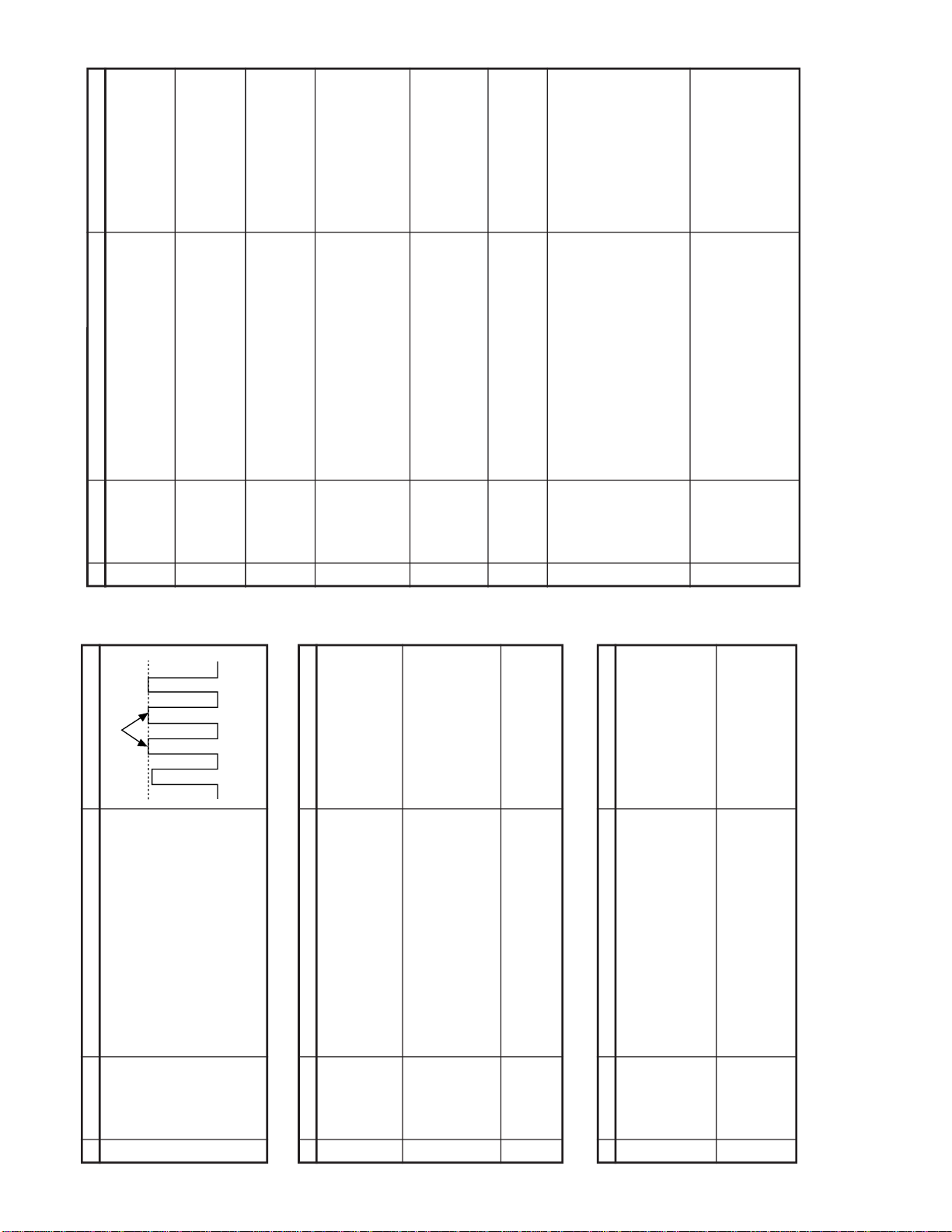
EEPROM ITEMS OSD DATA LENGTH
INITIAL DATA
21R2BK REMARK
AGC TAKE OVER POINT AGC 0~63 14 ADJ
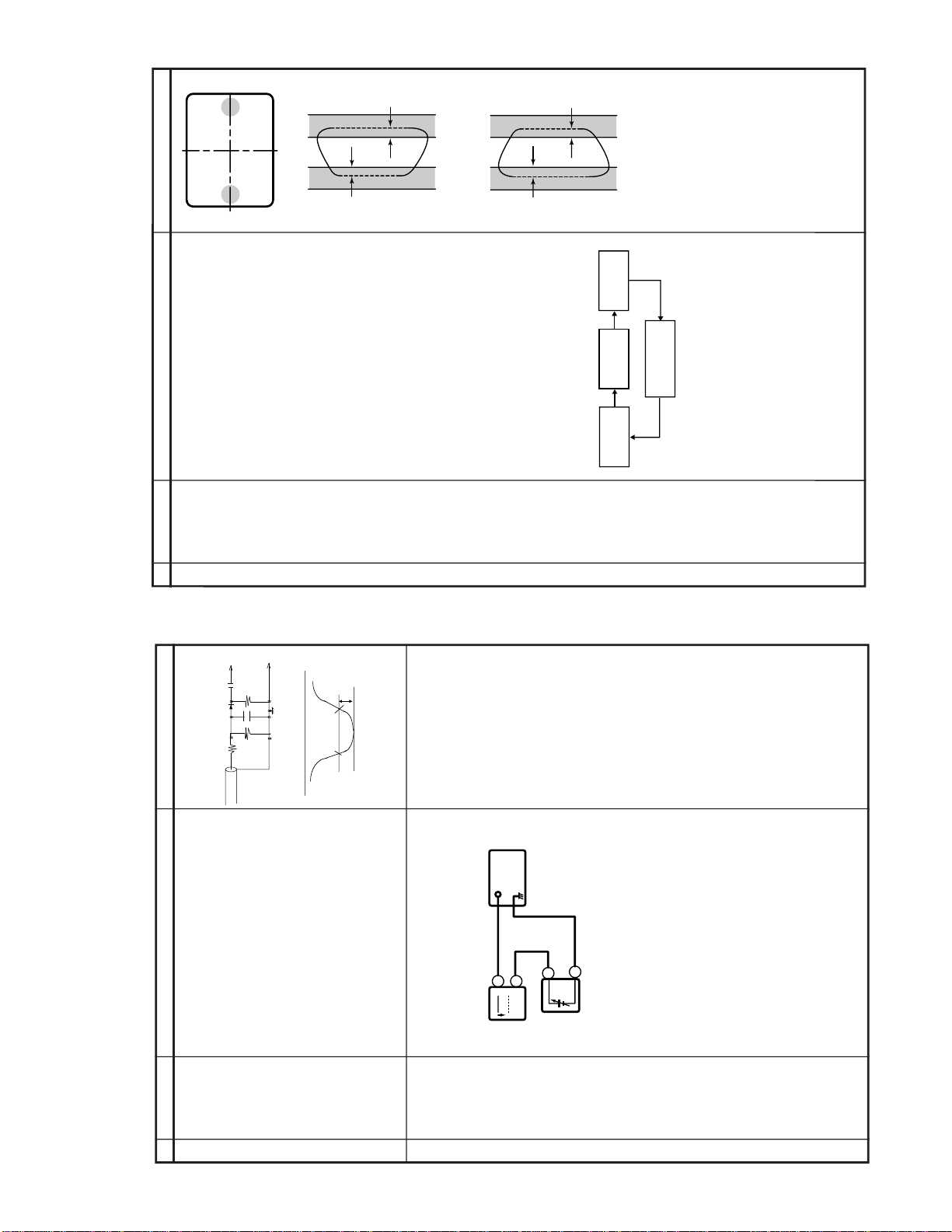
VERTICAL SLOPE V-LIN 0~63 32 ADJ
VERTICAL AMPLITUDE V-AMP 0~63 32 ADJ
VERTICAL SHIFT V-CENT 0~63 32 ADJ
HORIZONTAL SHIFT H-CENT 0~63 32 ADJ
EAST-WEST WIDTH H-SIZE 0~63 32 32
HORIZONTAL PARALLELOGRAM EW// 0~63 32 32
EAST-WEST PARABOLA/WIDTH PARA 0~63 32 32
EAST-WEST UPPER CORNER PARABOLA COR (U) 0~63 32 32
EAST-WEST LOWER CORNER PARABOLA COR (L) 0~63 32 32
EAST-WEST TRAPEZIUM TRAPE 0~63 32 32
HORIZONTAL BOW HB 0~63 32 32
S-CORRECTION S-COR 0~63 0 20
WHITE POINT RED STD WHITE TEMP DRI-RS 0~63 32 32
WHITE POINT GREEN STD WHITE TEMP DRI-GS 0~63 32 ADJ
WHITE POINT BLUE STD WHITE TEMP DRI-BS 0~63 32 ADJ
WHITE POINT RED COOL WHITE TEMP DRI-RC 0~63 25 27
WHITE POINT GREEN COOL WHITE TEMP DRI-GC 0~63 32 ADJ Data(DRI-GS)-5
WHITE POINT BLUE COOL WHITE TEMP DRI-BC 0~63 32 ADJ
Same as data (DRI-BS)
WHITE POINT RED WARM WHITE TEMP DRI-RW 0~63 32 32
WHITE POINT GREEN WARM WHITE TEMP DRI-GW 0~63 32 ADJ Data (DRI-GS)-7
WHITE POINT BLUE WARM WHITE TEMP DRI-BW 0~63 32 ADJ Data (DRI-BS)-7
MAX VOLUME SUB-VOL 0~63 63 63
SUB CONTRAST SUB-CON 0~63 63 63
SUB COLOUR SUB-COL 0~63 32 ADJ
SUB BRIGHTNESS SUB-BRI 0~63 32 ADJ
SUB TINT SUB-TINT 0~63 32 ADJ
SUB SHARPNESS SUB-SHP 0~63 32 20
MAX HOTEL VOLUME HTL-VOL 0~63 32 32
HOTEL PROGRAM NUMBER HTL-PRG
0~99 OR>99FOR NONE
255 255
OSD GRB REFERENCE RGB 0~15 15 15
BLACK LEVEL OFF-SET R CUT-R 0~63 32 ADJ
BLACK LEVEL OFF-SET G CUT-G 0~63 32 ADJ
CATHODE DRIVE LEVEL CDL 0~15 0 9
Y-DELAY TIME FOR PAL(TV) [YD] DL-PT 0~15 12 12
Y-DELAY TIME FOR SECAM(TV) [YD] DL-ST 0~15 15 15
Y-DELAY TIME FOR N358 (TV) [YD] DL-3T 0~15 12 12
Y-DELAY TIME FOR N443 (TV) [YD] DL-4T 0~15 12 12
Y-DELAY TIME FOR B/W (TV) [YD] DL-TV 0~15 12 12
Y-DELAY TIME FOR PAL (AV) [YD] DL-PA 0~15 12 12
Y-DELAY TIME FOR SECAM (AV) [YD] DL-SA 0~15 15 15
Y-DELAY TIME FOR N358 (AV) [YD] DL-3A 0~15 12 12
Y-DELAY TIME FOR N443 (AV) [YD] DL-4A 0~15 12 12
Y-DELAY TIME FOR B/W (AV) [YD] DL-AV 0~15 12 12
COLOUR OFFSET (PAL) COL-OP 0~15 8 14
COLOUR OFFSET (SECAM) COL-OS 0~15 8 14
COLOUR OFFSET (NTSC358) COL-O3 0~15 4 10
COLOUR OFFSET (NTSC443) COL-O4 0~15 4 10
SHARPNESS OFFSET (PAL) SHP-OP 0~15 8 8
SHARPNESS OFFSET (SECAM) SHP-OS 0~15 4 4
SHARPNESS OFFSET (NTSC358) SHP-O3 0~15 12 8
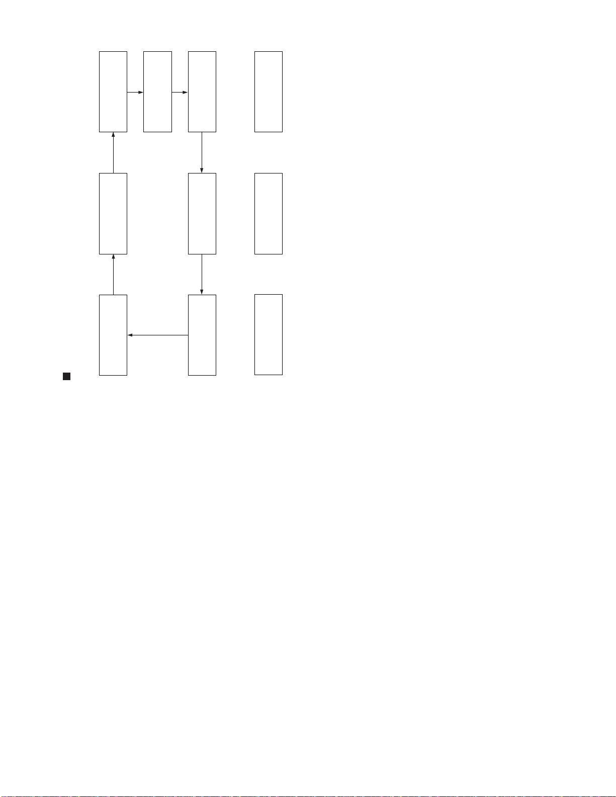
AFTER SHORT JA 137 & JA 138 ,AND TURN ON THE MAIN POWER SWITCH,READ DATA FROM EEPROM
ADDRESS 00H ~ 03H,AND COMPARE TO THE LIST BELOW, IF DIFFERENT, INITIALIZE THE EEPROM.
Address : Data Address : Data
00H : 55H 02H : 43H
01H : 4FH 03H : A1H
EEPROM ITEMS OSD DATA LENGTH
INITIAL DATA
21R2BK REMARK
SHARPNESS OFFSET (NTSC443) SHP-O4 0~15 8 8
VERTICAL SCAN DISABLE VSD
0(DISABLE)/1(ENABLE)
00
BLACK STRETCH BKS
0(DISABLE)/1(ENABLE)
11
AUTOMATIC VOLUME LEVELING AVL
0(DISABLE)/1(ENABLE)
11
FAST FILTER IF-PLL FFI
0(DISABLE)/1(ENABLE)
00
ENABLE VERTICAL GUARD (RGB BLANKING)
EVG
0(DISABLE)/1(ENABLE)
11
EHT TRACKING MODE (HCO) EHT
0(DISABLE)/1(ENABLE)
11
OVERSCAN SWITCH OFF OSO
0(DISABLE)/1(ENABLE)
00
AUTO COLOUR LIMIT ACL
0(DISABLE)/1(ENABLE)
00
FORCED COLOUR LIMIT FCO
0(DISABLE)/1(ENABLE)
00
SOUND SYSTEM M S-M
0(DISABLE)/1(ENABLE)
00
SOUND SYSTEM DK S-DK
0(DISABLE)/1(ENABLE)
11
SOUND SYSTEM I S-I
0(DISABLE)/1(ENABLE)
11
SOUND SYSTEM BG S-BG
0(DISABLE)/1(ENABLE)
11
PLAYBACK SECAM P-SECAM
0(DISABLE)/1(ENABLE)
11
FE (RF) NTSC 3.58 F-N358
0(DISABLE)/1(ENABLE)
00
FE (RF) NTSC 4.43 F-N443
0(DISABLE)/1(ENABLE)
11
FE (RF) SECAM F-SECAM
0(DISABLE)/1(ENABLE)
11
VIDEO MUTE AT IDENT LOSS VMI
0(DISABLE)/1(ENABLE)
11
VIDEO MUTE AT PROGRAM/SOURCE CHANGE
VMC
0(DISABLE)/1(ENABLE)
11
HOTEL MODE HTL
0(DISABLE)/1(ENABLE)
00
REDUCED FM DEMODULATOR GAIN FOR BTSC SIGNAL
BTSC
0(DISABLE)/1(ENABLE)
00
NUMBER OF EXTERNALAV SOURCE AV
0 FOR1 AV/1 FOR 2AV
10
FM WINDOW SELECTION FMWS
0(DISABLE)/1(ENABLE)
00
SOUND MUTE BIT 0 SM0
0(DISABLE)/1(ENABLE)
11
SOUND MUTE BIT 1 SM1
0(DISABLE)/1(ENABLE)
00
THAI LANGUAGE THA
0(DISABLE)/1(ENABLE)
00
ARABIC LANGUAGE ARA
0(DISABLE)/1(ENABLE)
11
MALAY LANGUAGE MAL
0(DISABLE)/1(ENABLE)
11
CHINESE LANGUAGE CHI
0(DISABLE)/1(ENABLE)
11
FRENCH LANGUAGE FRE
0(DISABLE)/1(ENABLE)
11
RUSSIAN LANGUAGE RUS
0(DISABLE)/1(ENABLE)
10
FORCED V-SYNC SLICING LEVEL FSL
0(DISABLE)/1(ENABLE)
00
SYNC OF OSD HP2
0(DISABLE)/1(ENABLE)
00
TUNER SELECTION (0:SHARP/ALPS;1:MURATA)
CPT
0(DISABLE)/1(ENABLE)
00
BILINGUAL BIL
0(DISABLE)/1(ENABLE)
00
IF AGC SPEED BIT 0 AGC0
0(DISABLE)/1(ENABLE)
11
IF AGC SPEED BIT 1 AGC1
0(DISABLE)/1(ENABLE)
00
PHI-1 TIME CONSTANT (RF) FOA-FE
0(DISABLE)/1(ENABLE)
00
PHI-1 TIME CONSTANT (RF) FOB-FE
0(DISABLE)/1(ENABLE)
00
PHI-1 TIME CONSTANT (OFF AIR) FOA-AV
0(DISABLE)/1(ENABLE)
11
PHI-1 TIME CONSTANT (OFF AIR) FOB-AV
0(DISABLE)/1(ENABLE)
11
LED BLINK SPEED LED_F
0(DISABLE)/1(ENABLE)
01
VOLUME CONTROL PWM TABLE MSA
0(DISABLE)/1(ENABLE)
01
OUTPUT VERTICAL GUARD NDF
0(DISABLE)/1(ENABLE)
01
NOTE :
1) Please follow the fixed data according to model.
2) ADJ meaning adjustment data.