Sharp 26PL83M User manual

1
26PL83M
SHARP CORPORATION
In the interests of user-safety (Required by safety regulations in some countries ) the set should be restored to its
original condition and only parts identical to those specified should be used.
Page
»ELECTRICAL SPECIFICATIONS .........................................................................................................1
»IMPORTANT SERVICE SAFETY PRECAUTION .................................................................................2
»LOCATION OF USER'S CONTROL .....................................................................................................4
»INSTALLATION AND SERVICE INSTRUCTIONS................................................................................5
»SERVICE ADJUSTMENT .....................................................................................................................9
»CHASSIS LAYOUT .............................................................................................................................12
»BLOCK DIAGRAM ..............................................................................................................................14
»SCHEMATIC DIAGRAMS...................................................................................................................15
»PRINTED WIRING BOARD ASSEMBLIES ........................................................................................25
»REPLACEMENT PARTS LIST............................................................................................................30
»PACKING OF THE SET ......................................................................................................................39
CONTENTS
SPEAKER
SIZE ........................................................12 x 6 cm oval (2 pcs.)
VOICE COIL IMPEDANCE .............................. 8 ohm at 400 Hz
ANTENNA INPUT IMPEDANCE
VHF/UHF.....................................................75 ohm Unbalanced
TUNING RANGES
VHF-Channels...............................................................2 thru 13
UHF-Channels ............................................................14 thru 69
CATV Channels...........................................................1 thru 125
POWER INPUT..................................................... AC120V, 60 Hz
POWER RATING .................................................................. 141W
PICTURE SIZE ........................................ 2,032.5cm2 (315sq inch)
CONVERGENCE ............................................................. Magnetic
SWEEP DEFLECTION .................................................... Magnetic
FOCUS ............................................... Hi-Bi-Potential Electrostatic
INTERMEDIATE FREQUENCIES
Picture IF Carrier Frequency ..................................... 45.75 MHz
Sound IF Carrier Frequency...................................... 41.25 MHz
Color Sub-Carrier Frequency .................................... 42.17 MHz
(Nominal)
AUDIO POWER
OUTPUT RATING ............... 5.0W +5.0W (at 10% distortion and
Dual CH Operate)
Specifications are subject to change without
prior notice.
ELECTRICAL SPECIFICATIONS
SERVICE MANUAL
S81Y926PL83M/
COLORTELEVISION
Chassis No. MS-B
26PL83M
MODEL
P
POWER POWER
PUSHOPEN
MTSSTEREO

2
26PL83M
IMPORTANT SERVICE SAFETY PRECAUTION
ËService work should be performed only by qualified service technicians who are
thoroughly familiar with all safety checks and the servicing guidelines which follow:
CAUTION: FOR CONTINUED
PROTECTION AGAINST A
RISK OF FIRE, REPLACE
ONLY WITH SAME TYPE 4A-
125V FUSE.
X-RADIATION AND HIGHVOLTAGE LIMITS
1. Be sure all service personnel are aware of the
proceduresandinstructionscoveringX-radiation.The
only potential source of X-ray in current solid state
TVreceivers is thepicture tube. However, the picture
tube does not emit measurable X-Ray radiation, if
the high voltage is as specified in the "High Voltage
Check" instructions.
It is only when high voltage is excessive that X-
radiation is capable of penetrating the shell of the
picture tube including the lead in the glass material.
The important precaution is to keep the high voltage
below the maximum level specified.
2. It is essential that servicemen have available at all
times an accurate high voltage meter.
The calibration of this meter should be checked
periodically.
3. Highvoltage should always bekeptat the ratedvalue
−no higher. Operation at higher voltages may cause
a failure of the picture tube or high voltage circuitry
and;also, under certain conditions, may produce
radiation in exceeding of desirable levels.
4. Whenthe high voltage regulatoris operating properly
thereisnopossibilityofanX-radiationproblem.Every
timeacolorchassisisserviced,thebrightnessshould
be tested while monitoring the high voltage with a
meter to be certain that the high voltage does not
exceed the specified value and that it is regulating
correctly.
5. Do not use a picture tube other than that specified or
make unrecommended circuit modifications to the
high voltage circuitry.
6. Whentroubleshootingand taking test measurements
onareceiverwithexcessivehighvoltage,avoidbeing
unnecessarily close to the receiver.
Do not operate the receiver longer than is necessary
to locate the cause of excessive voltage.
WARNING
1. For continued safety, no modification of any circuit
should be attempted.
2. Disconnect AC power before servicing.
3. Semiconductor heat sinks are potential shock
hazards when the chassis is operating.
4. The chassis in this receiver has two ground systems
which are separated by insulating material. The non-
isolated (hot) ground system is for the B+ voltage
regulator circuit. The isolated ground system is for
the low B+ DC voltages and the secondary circuit of
the high voltage transformer.
To prevent electrical shock use an isolation
transformer between the line cord and power
receptacle, when servicing this chassis.
SERVICING OF HIGH VOLTAGE SYSTEM
AND PICTURETUBE
When servicing the high voltage system,
remove the static charge by connecting a
10k ohm resistor in series with an insulated
wire (such as a test probe) between the pic-
ture tube ground and the anode lead. (AC
line cord should be disconnected from AC
outlet.)
1. Picturetubeinthisreceiveremploysintegralimplosion
protection.
2. Replace with tube of the same type number for
continued safety.
3. Do not lift picture tube by the neck.
4. Handle the picture tube only when wearing
shatterproof goggles and after discharging the high
voltage anode completely.
4A 125V

3
26PL83M
12345678901234567890123456789012123456789012345678901234567890121234567890123456789012345678901212
1
234567890123456789012345678901212345678901234567890123456789012123456789012345678901234567890121
2
1
234567890123456789012345678901212345678901234567890123456789012123456789012345678901234567890121
2
12345678901234567890123456789012123456789012345678901234567890121234567890123456789012345678901212
12345678901234567890123456789012123456789012345678901234567890121234567890123456789012345678901212
1
234567890123456789012345678901212345678901234567890123456789012123456789012345678901234567890121
2
12345678901234567890123456789012123456789012345678901234567890121234567890123456789012345678901212
SAFETY NOTICE
Many electrical and mechanical parts in television
receivers have special safety-related characteristics.
These characteristics are often not evident from visual
inspection, nor can protection afforded by them be
necessarilyincreasedbyusingreplacementcomponents
rated for higher voltage, wattage, etc.
Replacement parts which have these special safety
characteristics are identified in this manual; electrical
components having such features are identified by "å"
and shaded areas in the Replacement Parts Lists and
Schematic Diagrams.
IMPORTANT SERVICE SAFETY PRECAUTION
(Continued)
1. Inspect all lead dress to make certain that leads are
not pinched or that hardware is not lodged between
the chassis and other metal parts in the receiver.
2. Inspect all protective devices such as non-metallic
control knobs, insulating materials, cabinet backs,
adjustment and compartment covers or shields,
isolation resistor-capacity networks, mechanical
insulators, etc.
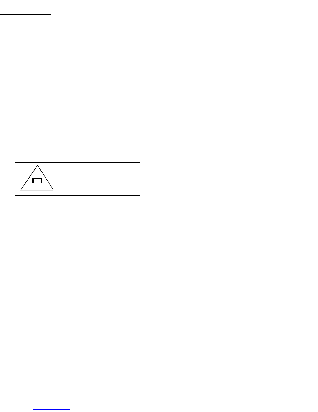
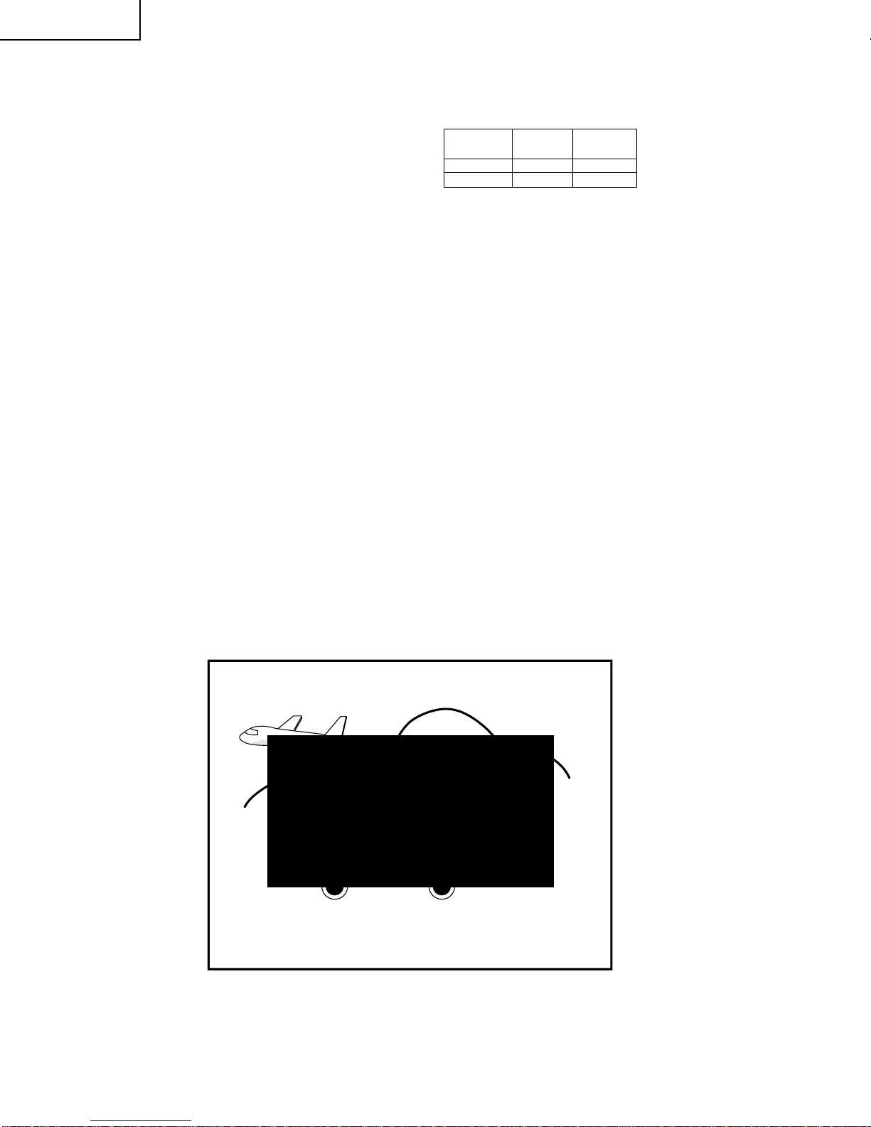
3. To be sure that no shock hazard exists, check for
leakage current in the following manner.
•Plug the AC cord directly into a 120 volt AC outlet,
(Do not use an isolation transformer for this test).
•Using two clip leads, connect a 1.5k ohm, 10 watt
resistorparalleledbya0.15µFcapacitorinserieswith
all exposed metal cabinet parts and a known earth
ground,suchaselectrical conduit or electricalground
connected to earth ground.
•Use anAC voltmeter having with 5000 ohm per volt,
or higher, sensitivity to measure theAC voltage drop
across the resistor.
BEFORE RETURNINGTHE RECEIVER
(Fire & Shock Hazard)
Before returning the receiver to the user, perform
the following safety checks.
•Connect the resistor connection to all exposed metal
parts having a return to the chassis (antenna, metal
cabinet, screw heads, knobs and control shafts,
escutcheon, etc.) and measure the AC voltage drop
across the resistor.
AII checks must be repeated with the AC line cord
plug connection reversed. (If necessary, a non-
polarized adapter plug must be used only for the
purpose of completing these check.)
Anycurrent measured mustnot exceed 0.5milliamp.
Any measurements not within the limits outlined
above indicate of a potential shock hazard and
corrective action must be taken before returning the
instrument to the customer.
For continued protection, replacement parts must be
identical to those used in the original circuit. The use of
substitutereplacementpartswhichdonothavethesame
safety characteristics as the factory recommended
replacement parts shown in this service manual, may
create shock, fire, X-radiation or other hazards.
1.5k ohm
10W
0.15µF
TEST PROBE
TO EXPOSED
METAL PARTS CONNECT TO
KNOWN EARTH
GROUND

4
26PL83M
LOCATION OF USER'S CONTROL
POWER POWER MTSSTEREO
VIDEO IN 2 L-AUDIO-R
– VOL
+CH MENU
POWER POWER – VOL +CH
√
√
MENU
Front Panel
CHANNELUP/DOWN
(') Selects next higher channel.
(") Selects next lower channel.
SENSOR AREA FOR
REMOTE CONTROL
VOLUME UP/DOWN
(+) Increases sound.
(–) Decreases sound.
POWER
Press →On.
Press again →Off.
MENU
Press →Accesses MAIN
MENU.
Press again →Exits MAIN
MENU.
Infrared Transmitter Window
DISPLAY
Press→Displays receivingchannel for
four seconds.
Press again →Removes display.
• Temporarily displays receiving
channel when in Closed Caption
mode.
INPUT
Press →Switch to external video
INPUT 1 mode.
Press2times→Switchtoexternalvideo
INPUT 2 mode.
Press 3 times →Switch to external
COMPONENT mode.
Press 4 times →Switch back to the
original TV mode.
ENTER
Usedin someinstanceswhere aCable
Converter Box requires an “enter”
command after selecting channels,
when using the REMOTE KEYPAD
button.
CHANNELUP/DOWN
(') Selects next higher channel.
(") Selects next lower channel.
•Moves the “ »” mark of the MENU
screens.
MUTE
Press →Mutes sound.
Press again →Restores sound.
• CLOSED CAPTION appears when
sound is muted.
1 2 3
4 5 6
7 8 9
0
100
POWER
TV
DVD
VCR
MENU MUTE
PAUSE
FLASHBACK
DISPLAY
INPUT
TV • CATV •VCR • DVD
STOP REC
REW PLAY FF
CH/SKIP
VOL
—
CH
CH
VOL
+
ENTER
A B C D
PERSONAL PREFERENCE
CATV TV
DVD VCR
POWER
Press →On.
Press again →Off.
REMOTE KEYPAD
Accesses any channel from keypad.
FLASHBACK
Returns to previous channel.
PERSONAL PREFERENCE
With the Personal Preference buttons,
you can program your favorite
programs by using the 4 categoriesA,
B, C and D. The channels can be
accessed quickly by using these
buttons.
VOLUME UP/DOWN
(+) Increases sound.
(–) Decreases sound.
• In menu mode, changes or selects
the TV adjustments.
MENU
Press →Accesses MAIN MENU.
Press again →Exits MAIN MENU.
CATV/DVD-TV/VCR MODE SELECT
SWITCH
In TV/VCR position, sends power and
channel select commands (Channel
up/down and RandomAccessbuttons)
to the TV and VCR control.
In CATV/DVD position, sends power
and channel select commands to a
cable TV converter and DVD control.
DVD/VCR CONTROL
Basic Remote Control Functions
VIDEO/AUDIO IN2 TERMINALS

5
26PL83M
CIRCUIT PROTECTION
The receiver is protected by a 4.0A fuse (F701),
mounted on PWB-A, wired into one side of the AC
line input.
X-RADIATION PROTECTOR CIRCUIT TEST
After service has been performed on the horizontal
deflection system, high voltage system, B+ system,
test the X-Radiation protection circuit to ascertain
proper operation as follows:
1. Apply 120V AC using a variac transformer for
accurate input voltage.
2. Allow for warm up and adjust all customer controls
for normal picture and sound.
3. Receive a good local channel.
4. Connect a digital voltmeter to TP651 and make sure
that the voltmeter reads 13.2 ±0.7V.
5. Apply external 16.3V DC at TP651 by using an
external DC supply, TV must be shut off.
6. To reset the protector, unplug the AC cord and plug
the AC cord power on. Now make sure that normal
picture appears on the screen.
7. If the operation of the horizontal oscillator does not
stop in step 5, the circuit must be repaired before the
set is returned to the customer.
HIGH VOLTAGE CHECK
High voltage is not adjustable but must be checked
to verify that the receiver is operating within safe
and efficient design limitations as specified checks
should be as follows:
1. Connect an accurate high voltage meter between
ground and anode of picture tube.
2. Operate receiver for at least 15 minutes at 120V AC
linevoltage,withastrongairsignaloraproperly tuned
in test signal.
3. Enter the service mode and select the service
adjustment"V18"andBus data "01" (Y-mute on, CRT
Cut Off).
4. Thevoltage should beapproximately 29.0kV (at zero
beam).
Ifacorrectreadingcannotbeobtained,checkcircuitry
formalfunctioningcomponents. Afterthevoltagetest,
make Y-mute off to the normal mode.
INSTALLATION AND SERVICE INSTRUCTIONS
Note: (1)When performing any adjustments to resistor controls and transformers use non-metallic
screwdrivers or TV alignment tools.
(2)Before performing adjustments, the TV set must be on at least 15 minutes.

6
26PL83M
Figure A.
V01 02
CHANNEL
SERVICE ADJUSTMENT NUMBER
DATANUMBER
For adjustments of this model, the bus data is converted to various analog signals by the D/A converter
circuit.
Note: There are still a few analog adjustments in this series such as focus and master screen voltage.
Follow the steps below whenever the service adjustment is required. See "Table-B" to determine, if serv-
ice adjustments are required.
1. Service mode
Before putting unit into the service mode, check that
customer adjustments are in the normal mode. Use
the reset function in the video adjustment menu to
ensure customer controls are in their proper (reset)
position.
2. Service number selection
Once in the service mode, press the Ch-up or Ch-
down button on the remote controller or at the set.
The service adjustment number will vary in
increments of one, from "V01" to "P08". Select the
item you wish to adjust.
3. Data number selection
PresstheVol-up or Vol-downbuttontoadjustthedata
number.
To enter the service mode and exit serv-
ice mode.
To enter the service mode manually just press and hold
the Vol-down and Ch-up buttons at the same time, plug
the AC cord into a wall socket.
Now the TV set is switched on and enters the service
mode.
To exit the service mode, turn the television off by
pressing the power button.
55(085)

7
26PL83M
SERVICE
NUMBER DATA
ADJUSTMENT ITEM
INITIAL VALUE
RANGE
V01 PICTURE 03 0-15(00h-0Fh)
V02 TINT 3E 0-127(00h-7Fh)
V03 COLOR 2D 0-127(00h-7Fh)
V04 SUB-COLOR 10 0-31(00h-1Fh) Must be set to "10"
V05 BRIGHT 4D 0-127(00h-7Fh)
V06 RCUT-OFF 40 64-255(40h-FFh)
V07 GCUT-OFF 40 64-255(40h-FFh)
V08 BCUT-OFF 40 64-255(40h-FFh)
V09 G DRIVE 40 0-127(00h-7Fh)
V10 B DRIVE 40 0-127(00h-7Fh)
V11 SHARP 14 0-63(00h-3Fh) Must be set to "1E"
V12 N PHASE 01 0-3(00h-03h) Must be set to "01"
V13 DCRESTORATION 00 0-3(00h-03h) Must be set to "00"
V14 BLACK STRETCH 03 0-3(00h-03h) Must be set to "03"
V15 ABL START POINT 03 0-3(00h-03h) Must be set to "03"
V16 ABL GAIN 02 0-3(00h-03h) Must be set to "02"
V17 γ POINT 00 0-3(00h-03h) Must be set to "00"
V18 Y-MUTE/V-STOP 00 0-2 "00"= Normal, "01"= No-Y, "02"= No-Y & No-Vertical
V19 ENERGY SAVE 28 0-63(00h-3Fh) Must be set to "28"
V20 RTONE-G F6 0-255(00h-FFh) Must be set to "F6"
V21 RTONE-B F6 0-255(00h-FFh) Must be set to "F6"
V22 BTONE-G 00 0-255(00h-FFh) Must be set to "00"
V23 BTONE-B 0A 0-255(00h-FFh) Must be set to "0A"
V24 LOW-G F7 0-255(00h-FFh) Must be set to "F7"
V25 LOW-B E8 0-255(00h-FFh) Must be set to "E8"
V26 ML-G 00 0-255(00h-FFh) Must be set to "00"
V27 ML-B F9 0-255(00h-FFh) Must be set to "F9"
V28 HIGH-G 03 0-255(00h-FFh) Must be set to "03"
V29 HIGH-B 06 0-255(00h-FFh) Must be set to "06"
V30 WPS 01 0-1 Must be set to "01"
V31 RGB CONTRAST 20 0-63(00h-3Fh) Must be set to "2A"
V32 Y-DL 02 0-7(00h-07h) Must be set to "02"
V33 Y-DL-INPUT 01 0-7(00h-07h) Must be set to "01"
V34 VSM GAIN 07 0-7(00h-07h) Must be set to "07"
V35 N COMB 01 0-1 Must be set to "01"
V36 BPF/TOF-INPUT 00 0-1 Must be set to "00"
V37 CORING 00 0-1 Must be set to "00"
V38 VSM PHASE 00 0-1 Must be set to "00"
V39 COLOR γ00 0-1 Must be set to "00"
V40 SHARP-INPUT 14 0-63(00h-3Fh) Must be set to "1E"
V41 TINT-INPUT 3E 0-127(00h-7Fh)
V42 PICTURE-COMPONENT 03 0-15(00h-0Fh)
V43 TINT-COMPONENT 10 0-31(00h-1Fh) Must be set to "10"
V44 COLOR-COMPONENT 30 0-127(00h-7Fh) Must be set to "35"
V45 BRIGHT-COMPONENT 4A 0-127(00h-7Fh)
V46 R CUT OFF-COMPONENT 40 64-255(40h-FFh)
V47 G CUT OFF-COMPONENT 40 64-255(40h-FFh)
V48 B CUT OFF-COMPONENT 40 64-255(40h-FFh)
V49 G DRIVE-COMPONENT 40 0-127(00h-7Fh)
V50 B DRIVR-COMPONENT 40 0-127(00h-7Fh)
V51 SHARP COMPONENT 14 0-63(00h-3Fh) Must be set to "1E"
V52 N PHASE-COMPONENT 01 0-3(00h-03h) Must be set to "01"
V53 C-TRAP 00 0-1 Must be set to "00"
R01 RF-AGC 24 0-63(00h-3Fh)
R02 PIF VCO coil – – —
R03 RF-AGC REF 5C 0-255(00h-FFh) Must be set to "5C"
D01 V POSITION 00 0-7(00h-07h)
D02 H POSITION 10 0-31(00h-1Fh)
D03 V SIZE 12 0-63(00h-3Fh) Must be set to "0B"
D04 H SIZE 1F 0-63(00h-3Fh)
D05 V-LINEARITY 07 0-15(00h-0Fh)
D06 V-S CORRECTION 08 0-15(00h-0Fh) Must be set to "08"
D07 EW PARABOLA 21 0-63(00h-3Fh) Must be set to "21"
D08 EW TRAPEZIUM 0E 0-31(00h-1Fh) Must be set to "0E"
D09 EW CORNER 0C 0-15(00h-0Fh) Must be set to "00"
ADJUSTMENT CONTENTS
Table - A

8
26PL83M
D10 AFC GAIN 02 0-3(00h-03h) Must be set to "02"
D11 V EHT 07 0-7(00h-07h) Must be set to "07"
D12 H EHT 03 0-7(00h-07h) Must be set to "03"
EX1 FAO VOLUME 24 0-50(00h-32h) Must be set to "24"
EX2 CC-POSITION 21 0-127(00h-7Fh)
EX3 INT 7A 0-255(00h-FFh) Must be set to "7A"
EX4 A-ATT 5A 0-127
OP1 OPTION1 BA 0-255(00h-FFh) Must be set to "A4"
OP2 OPTION2 01 0-7(00h-07h) Must be set to "03"
M01 INPUT LEVEL 09 0-15(00h-0Fh) Must be set to "09"
M02 MTS VCO 24 0-63(00h-3Fh)
M03 FILTER 1F 0-63(00h-3Fh)
M04 WIDEBAND 18 0-63(00h-3Fh)
M05 SPECTRAL 10 0-63(00h-3Fh)
P01 CONTRAST-PIP 32 0-127(00h-7Fh)
P02 TINT-PIP 29 0-63(00h-3Fh) Must be set to "29"
P03 COLOR-SAT-PIP 32 0-127(00h-7Fh)
P04 Y-OFFSET-PIP 09 0-31(00h-1Fh) Must be set to "09"
P05 HXA-PIP 0A 0-255(00h-FFh) Must be set to "0A"
P06 HADJ-PIP 00 0-15(00h-0Fh) Must be set to "00"
P07 FREE RUN-PIP 0B 0-15(00h-0Fh) Must be set to "0B"
P08 TINT-PIP-INPUT 24 0-63(00h-3Fh) Must be set to "24"
SERVICE
NUMBER DATA
ADJUSTMENT ITEM
INITIAL VALUE
RANGE ADJUSTMENT CONTENTS
Table - A
NECESSARY UNNECESSARY
ADJUSTMENT
PART REPLACED
IC2001
IC201
XData is stored in IC2102.
The adjustment is needed to compensate for characteristics of parts
including IC201 and MTS level (M01).
Holding down both the VOL-up and CH-up buttons on the TV set at service mode for more than 2 seconds will
automatically write the above initial values into IC2102.
NOTES
X
IC2102
IC3001
CRT
Holding down both the VOL-up and CH-up buttons on the TV set in
theservice modeformore than2seconds willautomaticallywrite the
aboveinitialvalues into IC2102.Then perform a completeadjustment.
Adjust items related to picture tube only.
Adjust items related to MTS only (M01~M05).
Table - B
X
X
X

9
26PL83M
SERVICE ADJUSTMENT
VCO Adjustment
1. Connecta digital voltmeter betweenpin(55) of IC201
and ground.
2. Receive a good local channel.
3. Enter the service mode and select the service
adjustment "R02".
4. Adjust T201 so that digital voltmeter reads
2.5±1.0VDC.
5. Adjustment is completed, remove the voltmeter,
return to "normal" mode.
RF AGC Adjustment
1. Receive a good local channel.
2. Enter the service mode and select the service
adjustment "R01".
3. Set the data value to point where no noise or beat
appears.
4. Select another channel to confirm that no noise or
beat appears.
Note 1 : You will have to come out of the service
mode to select another channel.
Note 2 : Setting the data to "00" will produce a black
raster.
Screen Adjustment
1. Receive a good local channel.
2. Enter the service mode and select the service
adjustment "V03" and set the data value to "00" to
set the color level to minimum. (Record original data
code under adjustment "V03" before changing) You
may skip this step, if you selected a B/W picture or
monoscope pattern.
3. Select the service adjustment "V18" and adjust the
data value to "01", this turn off the luminance signal
(Y-mute).
4. Adjust the master screen control until the raster
darkens to the point where raster is barely seen.
5. Adjusttheserviceadjustments"V06"red,"V07"green
and "V08" blue to obtain a good grey scale with
normal whites at low brightness level.
6. Select the service adjustment "V18" and reset data
to"00".Selecttheservice adjustment "V03" and reset
data to obtain normal color level.
7. For component input, the data value of "V46" red,
"V47" green and "V48" blue is adjusted to follow the
data value of "V06", "V07" and "V08" respectively.
8. Reset the master screen control to obtain normal
brightness range.
White Balance Adjustment
1. Receive a good local channel.
2. Enter the service mode and select the service
adjustment "V03" and set to "00" (minimum
color)(Record original data code under adjustment
"V03" before changing). "V03" does not have to be
adjusted,ifyou selected a B/Wpictureor monoscope
pattern.
3. Alternatelyadjusttheserviceadjustmentdataof"V09"
and "V10" until a good grey scale with normal whites
is obtained. (RF Input)
4. For component input, the data value of "V49" and
"V50" is adjusted to follow the data value of "V09"
and "V10" respectively.
5. Select the service adjustment "V03" and reset data
to obtain normal color level.
Picture Adjustment
1. Receive a good local channel.
2. Make sure the customer picture control is set to
maximum.
3. Enter the service mode and select the service
adjustment "V01".
4. Adjust the data value to achieve normal contrast
range.
Tint Adjustment
1. Receive a good local channel.
2. Set customer tint control to center of it's range.
3. Enter the service mode and select the service
adjustment "V02".
4. Adjust "V02" data value to obtain normal flesh tones.
5. Input same data to "V41".
Sub-Color Adjustment
1. Receive a good local channel.
2. Makesure the customer color control isset to center
position .
3. Enterthe service mode and select service adjustment
"V04".
4. Adjust "V04" data value to obtain normal color level.
Brightness Adjustment
1. Receive a good local channel.
2. Make sure the customer brightness control is set to
center position.
3. Enter the service mode and select the service
adjustment "V05".
4. Adjust "V05" data value to obtain normal brightness
level.

10
26PL83M
Vertical-Size and Linearity Adjustments
1. Receive a good local channel.
2. Enter the service mode and select the service
adjustment "D03" for V-size.
3. Adjust the "D03" bus data to get the proper V-size.
4. ForV-linearityadjustment,selectdata bus "D05"and
adjust to get the proper vertical linearity.
Note: Aging for 10 min before adjustment. After the
adjustment of V-center and V-size, re-
adjustment for this V-line.
Vertical Phase Adjustment
1. Enter the service mode and select the service
adjustment "D01".
2. Adjust "D01" data value so that picture is centered.
Horizontal Position Adjustment
1. Receive a good local channel.
2. Enter the service mode and select the service
adjustment "D02".
3. Adjust "D02" data value so that picture is centered.
Caption Position Adjustment (Horizontal)
1. Receive a good local channel.
2. Enter the service mode and select the service
adjustment "EX2".
3. Ablack text box appears on the screen. (see
Figure
B.
below)
4. Adjust"EX2" data value so that text box ispositioned
in the center of the screen.
Other Adjustments
1. Enter the service mode.
2. Adjust the following data values as listed below.
Figure B.
SERVICE ADJUST DATA
POSITION ITEM (Hex)
OP1 OPTION1 A4
OP2 OPTION2 03

11
26PL83M
ËMTS ADJUSTMENT
MTS Level Adjustment
1. Receive the following composite signal.
Monaural signal: 400Hz, 100% modulation
2. Connect the rms voltmeter to pin (39) of IC3001.
3. Enter the service mode and select the service
adjustment "M01" and set to "09".
4. Enter the service mode and select the service
adjustment "EX4".
5. Adjust the data so that the rms voltmeter reads 490
±10 mVrms.
MTS VCO Adjustment
1. Keep the unit in no-signal state.
2. Connectthe frequencycounter topin (39) of IC3001.
3. Connect a capacitor (100µF, 50V) in between
positive(+) side of C3005 and ground.
4. Enter the service mode and select the service
adjustment "M02"
5. Adjust the data so that the frequency counter reads
62.94 ±0.75kHz.
Filter Adjustment
1. Feed the following stereo pilot signal to pin (14) of
IC3001 .
Stereo pilot signal: 9.4kHz, 600mVrms.
2. Enter the service mode and select the service
adjustment "M03".
3. Adjust the data until "OK" appears in position on the
screen. Make sure the "OK" is displayed almost at
the center of the data range.
Separation Adjustment
1. Connect the rms voltmeter to pin (39) of IC3001.
2. Receive the following composite stereo signal 1.
Composite stereo signal: 30% modulation, left
channel only, noise reduction on, 300Hz
3. Enter the service mode and select the service
adjustment "M04".
4. Adjust the data until the AC voltage reading of the
RMS voltmeter is minimum.
5. Receive the following composite stereo signal 2.
Stereo signal: 30% modulation, left channel only,
noise reduction on, 3kHz
6. Enter the service mode and select the service
adjustment "M05".
7. Adjust the data until the AC voltage reading of the
rms voltmeter is minimum.
8. Take the above steps 1 thru 7 again for fine
adjustment.

13
26PL83M
12
121110987654321
A
B
C
D
E
F
G
H
CHASSIS LAYOUT

14
654321
A
B
C
D
E
F
G
H
26PL83M
BLOCK DIAGRAM

15
26PL83M
DESCRIPTION OF SCHEMATIC DIAGRAM
NOTES:
1. The unit of resistance "ohm" is omitted.
(K=k
Ω
=1000
Ω
, M=M
Ω
)
2. All resistors are 1/8 watt, unless otherwise noted.
3. All capacitors are µ F, unless otherwise noted.
(P=pF=µµF)
4. (G) indicates ±2% tolerance may be used.
5. indicates line isolated ground.
VOLTAGE MEASUREMENT CONDITIONS:
1. All DC voltages are measured with DVM connected
between points indicated and chassis ground, line
voltageset at 120VACandallcontrols setfor normal
picture unless otherwise indicated.
2. All voltages measured with 1000µ V B & W or Color
signal.
WAVEFORM MEASUREMENT CONDITIONS:
1. Photographs taken on a standard gated color bar
signal, the tint setting adjusted for proper color. The
wave shapes at the red, green and blue cathodes of
the picture tube depend on the tint, color level and
picture control.
2. indicates waveform check points (See chart,
waveforms are measured from point indicated to
chassis ground.)
WAVEFORMS
11.2 Vp-p 22.3 Vp-p 31.0 Vp-p 40.5 Vp-p 55 Vp-p 65 Vp-p
71.1 Vp-p 81.5 Vp-p 930 Vp-p 053 Vp-p q5.4 Vp-p w0.8 Vp-p
e190 Vp-p r15 Vp-p t1050 Vp-p y900 Vp-p u220 Vp-p i27 Vp-p
o3.0 Vp-p p3.0 Vp-p a3.0 Vp-p s140 Vp-p d130 Vp-p f130 Vp-p
å
AND SHADED ( ) COMPONENTS
= SAFETY RELATED PARTS.
ç
MARK= X-RAY RELATED PARTS.
This circuit diagram is a standard one, printed circuits
may be subject to change for product improvement
without prior notice.

17
26PL83M
16
121110987654321
A
B
C
D
E
F
G
H
SCHEMATIC DIAGRAM: MAIN-1 Unit

19
26PL83M
18
121110987654321
A
B
C
D
E
F
G
H
SCHEMATIC DIAGRAM: MAIN-2 Unit

21
26PL83M
20
121110987654321
A
B
C
D
E
F
G
H
SCHEMATIC DIAGRAM: AV Unit

22
654321
A
B
C
D
E
F
G
H
26PL83M
SCHEMATIC DIAGRAM: CRT Unit

23
654321
A
B
C
D
E
F
G
H
26PL83M
SCHEMATIC DIAGRAM: CONTROL Unit

24
654321
A
B
C
D
E
F
G
H
26PL83M
SCHEMATIC DIAGRAM: MTS MODULE Unit
Table of contents
Other Sharp TV manuals

Sharp
Sharp 21HM-10C User manual

Sharp
Sharp LC-22CFE4000E User manual

Sharp
Sharp C-2890EES User manual

Sharp
Sharp 26SL72M User manual

Sharp
Sharp CX-3451 User manual

Sharp
Sharp LC-32LE352E-BK Manual

Sharp
Sharp 29RX5 User manual

Sharp
Sharp AQUOS LC-70UX500H User manual

Sharp
Sharp 28LS-92EC User manual

Sharp
Sharp 27L-S500 User manual

Sharp
Sharp 36R-S60 User manual

Sharp
Sharp 21AXS500 User manual

Sharp
Sharp 32HW-57EDE User manual

Sharp
Sharp LC-15B2MA User manual

Sharp
Sharp 19SV111 User manual

Sharp
Sharp 13N-M100B User manual

Sharp
Sharp 55BJ2KE User manual

Sharp
Sharp Aquos LC 15B1U User manual

Sharp
Sharp 32HW-57E ES User manual

Sharp
Sharp 14LK20A User manual