Sharp Aquas LC-52LE920UN User manual

SHAR~
AQuas
LC-52LE920UN
LC-60LE920UN
LIQUID CRYSTAL TELEVISION
TELEVISEUR ACL
TELEVISOR
CON PANTALLA
DE CRISTAL LlQUIDO
OPERATION MANUAL
MODE D'EMPLOI
MANUAL DE OPERACION
•
~,~.:DTv'
li~i#;itt4i"';1
HIGH-DErINITION
TELEVISION
[l]DOLBY
DIGITAL PLUS I
HIGH-DEFINITION
MULTIMEDIA
INTERFACE
Iiffi)®
CERTIFIED
NOM
1245
IMPORTANT :Please read this operation manual before starting operating the equipment.
IMPORTANT :Veuillez lire ce mode d'emploi avant de commencer autiliser I'appareil.
IMPORTANTE :Lea este manual de operaci6n antes de comenzar aoperar
el
equipo.

IMPORTANT:
To aid reporting
in
case
of
loss or theft, please record the
TV's model and serial numbers
in
the space provided. The
numbers are located at the rear
of
the
TV.
LC-52LE920UN
LC-60LE920UN
LIQUID CRYSTAL TELEVISION
ENGLISH
OPERATION MANUAL
IModel No.: ]
L..._s_er_'a_1
_N_O._:
_
IMPORTANT INFORMATION
WARNING: TO REDUCE THE RISK OF FIRE OR ELECTRIC SHOCK, DO
NOT
EXPOSE THIS PRODUCT TO RAIN OR MOISTURE.
A•
RISK OF ELECTRIC SHOCK
DO NOT OPEN
The lightning flash with arrow-head
symbol, within an equilateral triannle,
is intended
to
alert the user
to
the
presence
of
uninsulated "dangerous
voltage" within the
product's
enclosure that may be
of
sufficient
magnitude
to
constitute arisk
of
electric
shock
to persons.
CAUTION: TO REDUCE THE RISK OF ELECTRIC SHOCK,
DO NOT REMOVE COVER
(OR
BACK).
NO USER-SERVICEABLE PARTS INSIDE.
REFER SERVICING TO QUALIFIED SERVICE
PERSONNEL.
The exclamation point within a
triangle is intended
to
alert the user
to
the presence
of
important
operating and maintenance
(servicing) instructions
in
the
literature accompanying the product.
CAUTION: TO PREVENT ELECTRIC SHOCK, MATCH WIDE BLADE OF PLUG TO WIDE
SLOT, FULLY INSERT.
WARNING:
FCC Regulations state that any unauthorized changes
or
modifications
to
this equipment
not
expresslyI
approved by the manufacturer could void the user's authority
to
operate this equipment.
~
CAUTION:
This product satisfies FCC regulations when shielded cables and connectors are used
to
connect the unit
to
other
equipment.
To
prevent electromagnetic interference with electric appliances such as radios and televisions, use shielded
cables and connectors
for
connections.
@-
1

IMPORTANT INFORMATION
DECLARATION OF CONFORMITY:
SHARP
LIQUID
CRYSTAL
TELEVISION,
MODEL
LC-52LE920UN/LC-60LE920UN
This device complies with Part 15
of
the FCC Rules. Operation is subject
to
the following
two
conditions:
(1)
This device may not cause harmful interference, and
(2)
this device must
accept
any interference
received, including interference that may cause undesired operation.
RESPONSIBLE
PARTY:
SHARP
ELECTRONICS
CORPORATION
Sharp
Plaza,
Mahwah,
New
Jersey
07495-1163
TEL:
1-800-BE-SHARP
For
Business
Customers:
URL
http://www.sharpusa.com
INFORMATION:
This equipment has been tested and found to
comply
with the limits for aClass Bdigital device, pursuant
to
Part 15 of the FCC
Rules. These limits are designed
to
provide reasonable protection against harmful interference
in
aresidential installation. This
equipment generates, uses and can radiate radio frequency energy and, if not installed and used
in
accordance with the
instructions. may cause harmful interference
to
radio communications. However, there is no guarantee that interference will not
occur
in
aparticular installation. If this equipment does cause harmful interference to radio or television reception, which can be
determined by turning the equipment off and on, the user is encouraged to try to correct the interference by one or more of the
following measures:
--.
Reorient or relocate the receiving antenna.
Increase the separation between the equipment and receiver.
_.
Connect the equipment into an outlet on acircuit different from that
to
which the receiver
is
connected.
Consult the dealer or
an
experienced radiofTV technician for help.
FCC Compliance Statement
This device complies with part 15
of
the FCC Rules. Operation is subject to the following
two
conditions:
(1)
This device may not cause harmful interference, and
(2)
this device must accept any interference received, Including
Interference that may cause undesired operation.
Wireless
Radio
For
product
available
in
the USA/Canada market, only channel 1-11 can be operated. Selection
of
other channels is not possible.
This device is going to be operated
in
5.15-5.25GHz frequency range, it is restricted
in
indoor environment only.
Important: Any changes
or
modifications not expressly approved
by
the party responsible for compliance could void the user's
authority
to
operate the equipment.
FCC Radiation Exposure Statement: This equipment complies with FCC radiation exposure limits set forth for
an
uncontrolled
environment. This equipment should be installed and operated with minimum distance 20cm between the radiator &your body.
Industry Canada Statement
This Class Bdigital apparatus complies with Canadian ICES-003.
Cet appareil numerique de
la
classe
Best
conforme a
la
norme NMB-003 du Canada.
Operation is subject to the following
two
conditions:
(1)
This device may not cause harmful interference, and
(2)
this device
must
accept
any interference received. Including
interference that may cause undesired operation
of
the device. This device and its antenna(s) must not be colocated or
operation
in
conjunction with any other antenna or transmitter.
Wireless Radio
For product available
in
the USA/Canada market, only channel 1-11 can be operated. Selection
of
other channels is not possible.
The device could automatically discontinue transmission
in
case
of
absence
of
information to transmit, or operational failure.
Note that this is not intended
to
prohibit transmission
of
control or signaling information or the use of repetitive codes where
required by the technology.
Important: Any changes or modifications not expressly approved by the party responsible for compliance could void the user's
authority to operate the equipment.
IC Radiation Exposure Statement: This equipment complies with
IC
RSS-102 radiation exposure limits set forth for
an
uncontrolled environment. This equipment should be installed and operated with minimum distance 20 cm between the radiator
&your
body
"Note to
CATV
system installer: This reminder
is
provided to call the
CATV
system installer's attention to Article 820-40 of the National
Electrical Code that provides guidelines for proper grounding
and,
in
particular, specifies that the cable ground shall
be
connected to the
grounding system of the building,
as
close
to
the point of cable entry
as
practical."
This
product
qualifies
for
ENERGY
STAR
when
"Home"
is
selected
for
"TV
Location".
Setting
"TV
Location"
to
"Home"
allows
the
TV
to
achieve
an
energy-saving
status
for
household
use.
@-
2

DEAR
SHARP
CUSTOMER
Thank you for your purchase
of
the Sharp Liquid Crystal Television. To ensure safety and many years
of trouble-free operation of your product, please read the Important Safety Instructions carefully before
using this product.
IMPORTANT SAFETY INSTRUCTIONS
Electricity
is
used
to
perform many useful functions, but it can also cause personal injuries and property damage
if improperly handled. This product has been engineered and manufactured with the highest priority on safety.
However, improper use can result
in
electric shock and/or fire.
In
order
to
prevent potential danger, please
observe the following instructions when installing, operating and cleaning the product.
To
ensure your safety
and prolong the service life of your Liquid Crystal Television, please read the following precautions carefully
before using the product.
1)
Read these instructions.
2)
Keep these instructions.
3)
Heed all warnings.
4)
Follow all instructions.
5)
Do not use this apparatus near water.
6)
Clean only with dry cloth.
7)
Do not block any ventilation openings. Install
in
accordance with the manufacturer's instructions.
8)
Do not install near any heat sources such as radiators, heat registers, stoves, or other apparatus (including
amplifiers) that produce heat.
9)
Do
not defeat the safety purpose
of
the polarized or grounding-type plug. Apolarized plug has
two
blades
with one wider than the other. Agrounding type plug has
two
blades and athird grounding prong. The
wide blade
or
the third prong are provided for your safety. If the provided plug does not fit into your outlet,
consult an electrician for replacement of the obsolete outlet.
10)
Protect the power cord from being walked on or pinched particularly at plugs, convenience receptacles,
and the point where they exit from the apparatus.
11) Only use attachments/accessories specified by the manufacturer.
12)
Use only with the cart, stand, tripod, bracket, or table specified by the manufacturer,
or
sold
Il
with the apparatus. When acart is used, use caution when moving the cart/apparatus
combination
to
avoid injury from tip-over.
13)
Unplug this apparatus during lightning storms or when unused for long periods
of
time.
14)
Refer all servicing
to
qualified service personnel. Servicing
is
required when the apparatus has been
damaged
in
any way, such as power-supply cord or plug is damaged, liquid has been spilled or objects
have fallen into the apparatus, the apparatus has been exposed to rain or moisture, does not operate
normally, or has been dropped.
Additional Safety Information
15)
Power
Sources-
This product should be operated only from the type
of
power source indicated on the
marking label. If you are not sure
of
the type
of
power supply
to
your home, consult your product dealer
or
local power company. For products intended
to
operate from battery power, or other sources, refer
to
the
operating instructions.
16) Overloading-Do not overload wall outlets, extension cords,
or
integral convenience receptacles as this
can result
in
arisk of fire or electric shock.
17) Object and Liquid
Entry-
Never push objects of any kind into this product through openings as they may
touch dangerous voltage points
or
short-out parts that could result
in
afire or electric shock. Never spill
liquid
of
any kind on the product.
18) Damage Requiring
Service-
Unplug this product from the wall outlet and refer servicing to qualified
service personnel under the following conditions:
a)
When the AC cord or plug is damaged,
b)
If liquid has been spilled,
or
objects have fallen into the product,
c)
If the product has been exposed
to
rain or water,
d)
If the product does not operate normally by following the operating instructions.
Adjust only those controls that are covered by the operating instructions as
an
improper adjustment
of
other controls may result
in
damage and will often require extensive work by aqualified technician
to
restore the product
to
its normal operation,
e)
If the product has been dropped or damaged
in
any way, and
f)
When the product exhibits adistinct change
in
performance -this indicates aneed for service.
19)
Replacement
Parts-When
replacement parts are required, be sure the service technician has used
replacement parts specified by the manufacturer or have the same characteristics as the original part.
Unauthorized substitutions may result
in
fire, electric shock, or other hazards.
20) Safety Check-Upon completion of any service or repairs
to
this product, ask the service technician
to
perform safety checks
to
determine that the product is
in
proper operating condition.
21) Wall
or
ceiling
mounting-When
mounting the product on awall
or
ceiling, be sure
to
install the product
according
to
the method recommended by the manufacturer.
®D-
3

IMPORTANT SAFETY INSTRUCTIONS
ANTENNA
LEAD
IN
WIRE
ANTENNA
DISCHARGE UNIT
(NEC SECTION 810-20)
GROUNDING
J-.j-..::.::::::::,.l CONDUCTORS
(NEC SECTION 810-21)
~..c==-
GROUND CLAMPS
POWER SERVICE GROUNDING
ELECTRODE SYSTEM
(NEC ART 250, PART
H)
NEC -NATIONAL ELECTRICAL CODE
ELECTRIC
SERVICE
EQUIPMENT
EXAMPLE OF ANTENNA GROUNDING AS PER
NATIONAL ELECTRICAL CODE, ANSI/NFPA 70
•Outdoor Antenna Grounding -
If
an
outside antenna
is
connected to the television equipment, be sure the antenna
system
is
grounded so
as
to provide some protection against
voltage surges and built-up static charges.
Article 810 of the National Electrical Code, ANSI/NFPA 70,
provides information with regard to proper grounding of the
mast and supporting structure, grounding of the lead-in wire
to
an
antenna discharge unit, size of grounding conductors,
location of antenna-discharge unit, connection to grounding
electrodes, and requirements for the grounding electrode.
,
!~
•Water and Moisture -Do not use this product near water -for example, near abath tub, wash bowl, kitchen sink, or
laundry tub;
in
awet basement; or near aswimming pool; and the like.
•Stand -Do not place the product on
an
unstable cart, stand, tripod or table. Placing the product on
an
unstable base
can cause the product to
fall,
resulting
in
serious personal injuries as well as damage to the product. Use only acart,
stand, tripod, bracket or table recommended by the manufacturer or sold with the product. When mounting the product
on a wall, be sure to follow the manufacturer's instructions. Use only the mounting hardware recommended by the
manufacturer.
•Selecting the location -Select aplace with no direct sunlight and good ventilation.
•Ventilation
-The
vents and other openings
in
the cabinet are designed for ventilation.
Do
not cover or block these vents
and openings since insufficient ventilation can cause overheating and/or shorten the life of the product.
Do
not place
the product on abed, sofa, rug or other similar surface, since they can block ventilation openings. This product
is
not
designed for built-in installation;
do
not place the product
in
an
enclosed place such
as
abookcase or rack, unless proper
ventilation
is
provided or the manufacturer's instructions are followed.
•The front panel used
in
this product
is
made of glass. Therefore,
it
can break when the product
is
dropped or applied with
impact.
Be
careful not to be injured by broken glass pieces
in
case the panel breaks.
•Heat -The product should be situated away from heat sources such
as
radiators, heat registers, stoves, or other
products (inclUding amplifiers) that produce heat.
•The Liquid Crystal panel
is
avery high technology product with 2,073,600 pixels, giving you fine picture details.
Occasionally, afew non-active pixels may appear on the screen
as
afixed point of blue, green or red. Please note that
this does not affect the performance of your product.
•Lightning -For added protection for this television equipment during alightning storm, or when
it
is
left unattended and
unused for long periods of time, unplug it from the wall outlet and disconnect the antenna. This will prevent damage to
the equipment due to lightning and power-line surges.
•Power Lines -An outside antenna system should not be located
in
the vicinity of overhead power lines or other electric
light or power circuits, or where
it
can
fall
into such power lines or circuits. When installing
an
outside antenna system,
extreme care should be taken to keep from touching such power lines or circuits as contact with them might be fatal.
•To prevent
fire,
never place any type of candle or flames on the top or near the
TV
set.
•To prevent fire or shock hazard, do not place the AC cord under the
TV
set or other heavy items.
•Do not display astill picture for along time,
as
this could cause
an
afterimage to remain.
•To prevent fire or shock hazard, do not expose this product to dripping or splashing.
No objects filled with liquids, such as vases, should be placed on the product.
•Do not insert foreign objects into the product. Inserting objects
in
the air vents or other openings may
result
in
fire or electric shock. Exercise special caution when using the product around children.
Precautions when transporting the TV
•When transporting the
TV,
never carry
it
by holding or otherwise putting pressure onto the display.
Be
sure to always
carry the
TV
by two people holding
it
with
two
hands -one hand on each side of the
TV.
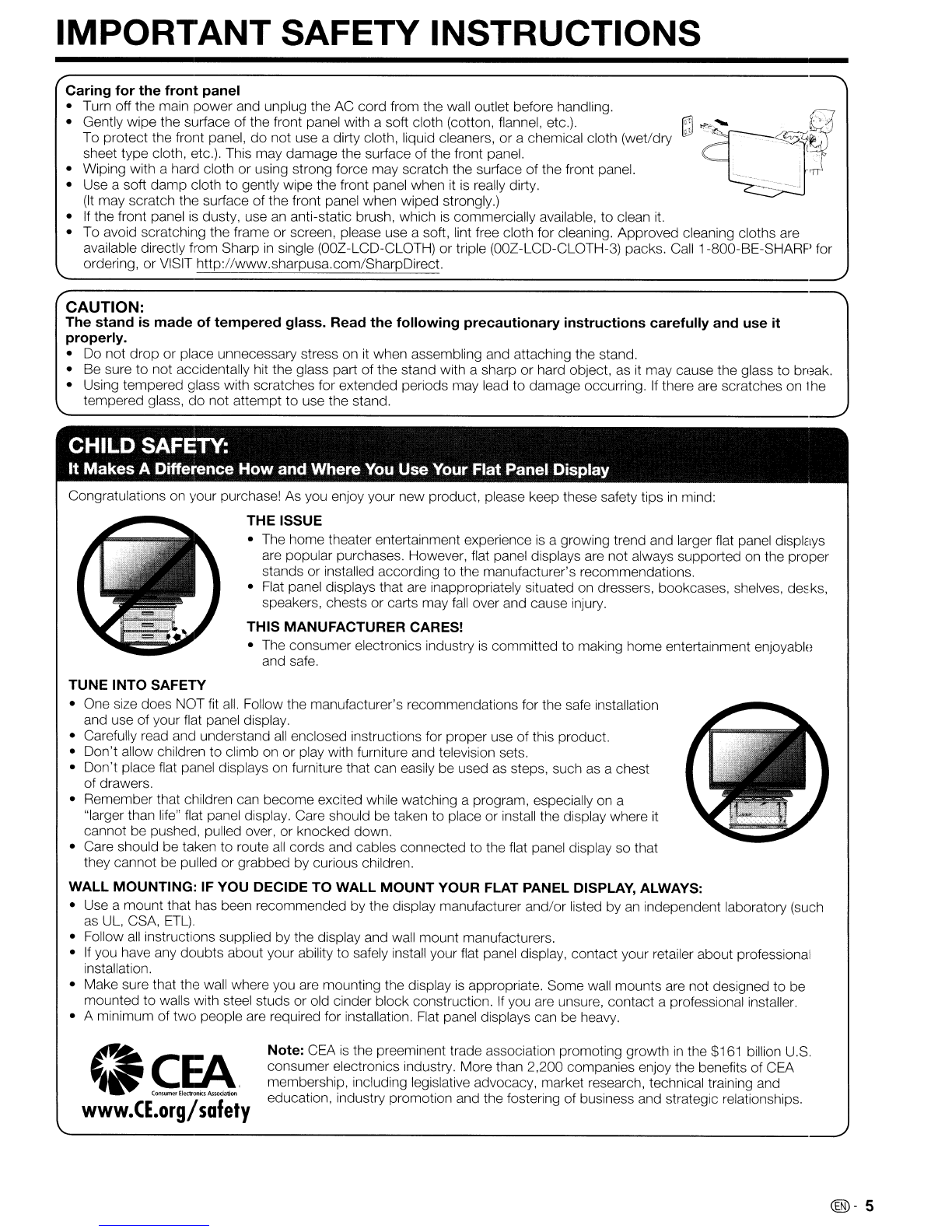
Caring for the cabinet
•Use asoft cloth (cotton, flannel, etc.) and gently wipe the surface of the cabinet.
•Using achemical cloth (wet/dry sheet type cloth, etc.) may deform the components
of
the main unit cabinet or cause
cracking.
•Wiping with ahard cloth or using strong force may scratch the surface
of
the cabinet.
•
If
the cabinet
is
very dirty, wipe with asoft cloth (cotton, flannel, etc.) soaked
in
neutral detergent diluted with water and
thoroughly wrung out, and then wipe with asoft dry cloth.
•The cabinet
is
primarily made of plastic. Avoid using benzene, thinner, and other solvents, as these may deform the
cabinet and cause the paint to peel off.
•Do not apply insecticides or other volatile liquids.
Also,
do
not allow the cabinet to remain
in
contact with rubber or vinyl products for along period of time. Plasticizers
inside the plastic may cause the cabinet to deform and cause the paint to peel off.
@-4

~
~ce:J':f""'.,
~.~;,.
I;lJ
...
_.~
.,
{
------------~~-l
IMPORTANT SAFETY INSTRUCTIONS
Caring
for
the
front panel
•Turn off the main power and unplug the AC cord from the wall outlet before handling.
•Gently wipe the surface of the front panel with asoft cloth (cotton, flannel, etc.).
To protect the front panel,
do
not use adirty cloth, liquid cleaners, or achemical cloth (wet/dry
sheet type cloth, etc.). This may damage the surface of the front panel.
•Wiping with ahard cloth or using strong force may scratch the surface of the front panel.
•Use asoft
damp
cloth
to
gently wipe the front panel when it
is
really dirty.
(It
may scratch the surface of the front panel when wiped strongly.)
•If the front panel
is
dusty, use
an
anti-static brush, which
is
commercially available, to clean
it.
•To avoid scratching the frame or screen, please use asoft, lint free cloth for cleaning. Approved cleaning cloths are
available directly from Sharp
in
single (OOZ-LCD-CLOTH) or triple (00Z-LCD-CLOTH-3) packs. Call1-800-BE-SHARP for
ordering, or VISIT http://www.sharpusa.com/SharpDirect.
CAUTION:
The
stand
is
made
of
tempered
glass.
Read
the
following precautionary instructions carefully and use it
properly.
•Do not drop or place unnecessary stress on
it
when assembling and attaching the stand.
•Be sure to not accidentally hit the glass part of the stand with asharp or hard object,
as
it
may cause the glass to break.
•Using tempered glass with scratches for extended periods may lead to damage occurring.
If
there are scratches on the
tempered glass,
do
not attempt to use the stand.
CHILD SAFETY:
It
Makes
ADifference
How
and Where You Use Your Flat Panel Display
Congratulations on your purchase!
As
you enjoy your new product, please keep these safety tips
in
mind:
THE ISSUE
•The horne theater entertainment experience
is
agrowing trend and larger flat panel displays
are popular purchases. However, flat panel displays are not always supported on the proper
stands or installed according
to
the manufacturer's recommendations.
•
Flat
panel displays that are inappropriately situated on dressers, bookcases, shelves, de::ks,
speakers, chests or carts may
fall
over and cause injury.
THIS MANUFACTURER CARES!
•The consumer electronics industry
is
committed
to
making home entertainment enjoyable
and safe.
TUNE INTO SAFETY
•One size does NOT fit
all.
Follow the manufacturer's recommendations for the safe installation
and use of your flat panel display.
•Carefully read and understand
all
enclosed instructions for proper use of this product.
•Don't allow children to climb on or play with furniture and television sets.
•Don't place flat panel displays on furniture that can easily be used
as
steps, such
as
achest
of drawers.
•Remember that children can become excited while watching aprogram, especially
on
a
"larger than life" flat panel display. Care should be taken to place or install the display where
it
cannot be pushed, pulled over, or knocked down.
•Care should be taken to route
all
cords and cables connected to the flat panel display so that
they cannot be pulled or grabbed by curious children.
WALL MOUNTING: IF YOU DECIDE TO WALL
MOUNT
YOUR FLAT PANEL DISPLAY, ALWAYS:
•Use amount that has been recommended by the display manufacturer and/or listed by
an
independent laboratory (such
as
UL,
CSA,
ETL).
•Follow
all
instructions supplied by the display and wall mount manufacturers.
•
If
you have any doubts about your ability to safely install your flat panel display, contact your retailer about professional
installation.
•Make sure that the wall where you are mounting the display
is
appropriate. Some wall mounts are not designed to be
mounted to walls with steel studs or old cinder block construction.
If
you are unsure, contact aprofessional installer.
• A minimum of
two
people are required for installation.
Flat
panel displays can be heavy.
<I~~.
www.CE.org/safety
Note: CEA
is
the preeminent trade association promoting growth
in
the $161 billion U.S.
consumer electronics industry. More than 2,200 companies enjoy the benefits of CEA
membership, including legislative advocacy, market research, technical training and
education, industry promotion and the fostering of business and strategic relationships,
@l-
5

Contents
IMPORTANT INFORMATION 1
DEAR SHARP CUSTOMER 3
IMPORTANT SAFETY INSTRUCTIONS
3-5
Supplied Accessories 7
QUICK REFERENCE
Attaching the Stand 7
QUICK INSTALLATION TiPS " 8
Using the Remote Control Unit ................. 8
Preparation
Antennas 9
Installing Batteries
in
the Remote Control Unit 9
Part Names
TV (Front) ...................................
..
10
TV
(Rear)
....................................
..
10
Remote Control Unit. ........................
..
11
Introduction to Connections
Experiencing HD Images ...................... 12
Types
of
Connection .... .... .... ... .... .... ... 12
Displaying
an
External Equipment Image. .. ..
..
12
Connecting to External Equipment
Connecting aBlu-ray Disc/DVD Player or
HD Cable/Satellite Set-top Box 13-14
Connecting aVCR, Game Console,
Camcorder or Cable/Satellite Set-top Box. ... 14
Connecting
an
Audio Amplifier. .... .... ... ...
..
15
Connecting a
PC
............................
..
16
Watching TV
Turning On/Off the Power 17
Initial Installation 17-18
Direct Button Operation
Changing Channels 19
Changing Volume ..... ... .... .... ... ... .... 19
MUTE 19
Sleep Timer ................................ 19
FLASHBACK 19
FREEZE 19
AV
MODE 20
INPUT 20
APPS 20
POWER SAVING 20
Closed Captions and
Digital Closed Captions
21
VIEW MODE 22
On-Screen Display Menu
On-Screen Display Menu Operation 23
Menu Operation Buttons 23
Menu Items 24
Picture Settings 25-26
Audio Settings 27
Power Control. ................................ 28
System Options 29-31
Initial Setup 32-35
Information 36-38
Enjoying Photo/MusicNideo Playback
Viewing Photos, Listening to Music and
Watching Videos 39
Photo Mode 40-41
Music Mode 42
Video Mode 42-43
USB Memory Device Compatibility 43
Other Viewing Options
Presetting Remote Control Function 44
Operating the Connected Equipment 44-45
Using AQUOS LINK
Controlling HDMI Equipment
Using AQUOS LINK 46-48
Link Operation Menu 48-49
Using aPC
Displaying aPC Image on the Screen 50
Adjusting the
PC
Image
51
Setting Audio Input
51
PC
Compatibility Chart
51
RS-232C Port Specifications 52
Using the Internet
Connecting to the Internet 53-54
Internet Setup 55-56
Displaying Updated Information and
Support Service 56
Entering Text (Software Keyboard) 57
Using the Browser 58-61
Enjoying Movies and Some Other Applications
via the Internet 62
Instantly Watching Movies from Netflix 62-63
Enjoying Movies and Internet Applications
with VUDU 64-65
Appendix
Removing the Stand 67
Setting the TV on the Wall 68
Optional Accessory 68
Troubleshooting 69-70
Troubleshooting -Error Message 70
Trademarks
71
Specifications
TV 72
Wireless LAN USB Adapter 73
Information
on
the Software License for
This Product..................................
..
74
Calling for Service .............................
..
75
LIMITED WARRANTY 75
Dimensional Drawings
•The dimensional drawings for the LCD
"TV
set are shown
on the inside back cover.
•The illustrations and on-screen displays
in
this operation manual are for explanation purposes and may vary slightly from
the actual operations.
•The examples used throughout this manual are based on the LC-60LE920UN model.
@-6

Supplied Accessories
Make sure the following accessories are provided with the product.
00
LC-52LE920UN
QJ
L[::J~
~~~~
tflff'ft'ft
Iff
Wireless LAN USB ada-Jter
(x
1)
Page 54
Stand unit
(x
1)
Page 7
"APA" size battery Cable clamp
(x2)
(x
1)
Page 9Page 8
•Connection guide (x1)
Remote control unit
(x
1)
Page 8
•Operation manual
(x
1)
ImID
•Always use the AC cord supplied with the
TV.
•The illustrations above are for explanation purposes and may vary slightly from the actual accessories.
QUICK
REFERENCE
Attaching
the
Stand
•Before attaching
(or
detaching) the stand, unplug the AC cord.
•Before performing work spread cushioning over the base area to lay the TV on. This will prevent
it
from being damaged.
•Attach the stand
in
the
correct direction.
•Do not remove
the
stand from the TV unless using an optional wall mount bracket to mount it.
•Be sure to follow
the
instructions. Incorrect installation
of
the
stand may result
in
the
TV falling over.
1Confirm that there
are
9screws
(5
short screws
and 4long screws) supplied with the stand unit.
~~~~
~~~~
~
2Attach the supporting post for the stand unit onto
the base
using'
he box for the stand unit
as
shown
below.
•The supporting post attaches to the base at
an
off-
centered location on the base. Be sure to attach the
supporting post
in
the direction indicated below and
attach the stand to the TV with the wider side of the
base facing forward.
3Insert the stand into the openings on the rear of the
N.
4Insert and tighten the 4screws into the 4holes
on
the rear of the stand unit.
5
CD
Insert the stand cover.
®Insert the screw to secure the stand cover.
,~~
Short screw
--.~
®
•To detach the stand, perform the steps
in
r,werse
order.
@-7

QUICK REFERENCE
QUICK INSTALLATION TIPS Using the Remote Control Unit
1Attach your antenna
to
the back of the television.
(See
page
9.)
2Connect the AC plug for the television into the AC
outlet.
Use the remote control unit by pointing
it
towards the
remote control sensor
on
the
TV.
Objects between the
remote control unit and the remote control sensor may
prevent proper operation.
1T(5m)
30°
30°
~
~ci~~
6666
ClCJCl
Cl
ClCJCJ
CJ
/.
I'
30°
----
30°
I
Remote control sensor
IMPORTANT:
IF
THE UNIT
DOES
NOT POWER
ON
-UNPLUG THE
TELEVISION
FROM
THE OUTLET AND REPEAT THE
INSTALLATION STEPS.
IF
YOU
STILL ENCOUNTER
NO
POWER, PLEASE CONTACT
US
AT
1-800-BE-SHARP.
•Cautions regarding the remote control unit
•Do not expose the remote control unit to shock.
In
addition,
do
not expose the remote control unit to liquids, and do not
place
in
an
area with high humidity.
•Do not install or place the remote control unit under direct
sunlight. The heat may cause deformation of the remote
control unit.
•The remote control unit may not work properly if the remote
control sensor
on
the
1V
is
under direct sunlight or strong
lighting.
In
such cases, change the angle of the lighting
or the 1V, or operate the remote control unit closer to the
remote control sensor.
mm
•TO PREVENT RISK OF ELECTRIC SHOCK,
DO
NOT
TOUCH UN-INSULATED PARTS OF ANY CABLES
WITH THE AC
CORD
CONNECTED.
3Bundle the cords properly with the cable clamp.
•Place the
1V
close to the AC outlet, and keep the power
plug within reach.
4When turning on the
TV
for the first time, press
POWER
on
the touch sensor panel
on
the front of
the
TV.
POWER
5Insert the batteries into the remote control unit.
(See
page
9.)
mm
•Speakers cannot be detached from the 1V.
•The
1V
can be rotated up to 20 degrees to right and left.
@-8

Preparation
Antennas
To
enjoy aclearer picture,
use
an
outdoor
antenna.
The
following is abrief explanation
of
the
types
of
connections
that
are
used
for
acoaxial cable. If
your
outdoor
antenna
uses a
75-ohm
coaxial
cable
with an
F-type
connector,
plug it into
the
antenna
terminal at
the
rear
of
the
TV set. For
connecting
the
antenna
cable
to
the
TV,
use
commercially
available cables.
Connecting Antenna Cable
•Connect the antenna cable
to
the
TV
using one of the methods
in
the illustration as shown
(CD,
@, @or @).
Home Antenna
75-ohm coaxial cable (round) terminal (75-ohm)
10-0
,;"",..
~
ca~\==<J
Coaxial cable
Home Antenna
Cable
"TV
lead-In terminal (75-ohm)
----------
~
ca~F=<J
Coaxial cable
300n5-ohm
adapter
300-ohm
twin-lead cable
lor
75-ohm
coaxial cable
300-ohm twin-lead cable
or
300-ohm twin-lead cable (flat) I
~5-ohm
coaxial cable (round)
VHF UHF
ANTENNA ANTENNA
@Separate
VHF/UHF
antenna
@Combination
VHF/
UHF
antenna
@
VHF/UHF
antenna
CD
Cable without aCATV
converter
iF-type
connector
-----.occ-
75-ohm coaxial cable
(round)
1.
A75-ohm system
is
generally around cable with F-type connector
that
can
easily
be
attached to aterminal without tools.
2.
A300-ohm system
is
aflat "twin-lead" cable that can
be
attached
to a75-ohm terminal through a300/75-ohm adapter. \
.",.
.",(
300-ohm twin-lead cable
(flat)
~
F-type
connector
should be finger-tightened only.
.....
. .
/.~~F-type
connector
When
connecting
the
RF
cable
to
the
TV
set,
do
not
tighten
F-type
~.__
Xv,
connector
with tools.
'cV~
If
tools
are used, it
may
cause
damage
to
your
TV set. (The breaking
--
"
\,
of
internal circuit, etc.) 75-ohm coaxial cable
Installing Batteries
in
the Remote Control Unit
If
the
remote
control
fails
to
operate
TV functions, replace
the
batteries
in
the
remote
control unit.
1
Open
the
battery
cover. 2Insert
two
"AAA"
size batteries (supplied
with
3Close
the
battery
cover.
the
product).
•Place the batteries
with their terminals
corresponding to the (+)
and
(- ) indications
in
the
battery compartment.
~
R.I
~~"'')
---
Emim
Improper
use
of batteries can result
in
chemical leakage or explosion.
Be
sure
to follow the instructions below.
•
Do
not
mix
batteries of different types. Different types of batteries
have
different characteristics.
•
Do
not
mix
old
and
new batteries. Mixing old
and
new batteries
can
shorten the
life
of new batteries
or
cause chemical leakage
in
old batteries.
•Remove batteries
as
soon
as
they
are
worn out. Chemicals that
leak
from batteries that come
in
contact with skin car cause a
rash.
If
you
find
any
chemical leakage,
Wipe
thoroughly with acloth.
•
The
batteries supplied with this product
may
have
ashorter
life
expectancy due to storage conditions.
•
If
you
will
not
be
lIsing the remote control unit for
an
extended period of time, remove batteries from
it.
@-9

Part Names
TV
(Front)
Remote control sensor
'--------.,.;.:.+--
OPC sensor
*1
(See
page 25.)
...
+V A
-EJ
I!!J
II
~I------
~
--
--
_~
~
J
JI
l=
Q
~
..
VOL-I+INPUT POWER
*2
CHV//\
MENU
*1
OPC: Optical Picture Control
*2
See pages 17 and 23 for using the touch sensor panel.
TV
(Rear)
*1
USB 1USB 1terminal
[ @ AUDIQQUT 1--AUDIO OUT terminal
--
DIGITAL AUDIO OUTPUT terminal
--
HDMI 4terminal
AVIN
--
AUDIO IN terminal
;::::::;::;=r::;;;;;;;;;;;
(shared for
PC
IN
and
HDMI1)
*2
--
HOM
I1terminal
ARC: Audio Return Channel
*1
Antenna/Cable
in
RS-232C terminal
COMPONENT terminals
USB2
---
USB 2terminal
*1
See pages 12 to 16 and
46
for external equipment connection.
*2
See page
51
for details on the Audio Select function.
@-
10

Part
Names
SHARP
AQuas
1POWER: Switch the TV power on or enter standby.
(See
page 17.)
2TV, STB,
DVD-VCR,
AUDIO: Switches the remote
control for
TV,
STB,
DVD,
BD, VCR and AUDIO ,)peration.
(See pages 44 to 45 for details.)
*To enter the code registration mode, you need to press
an
appropriate button (STB,
DVD-VCR
or
AUDIO) and
DISPLAY
at the same time.
3
External
equipment
operational
buttons:
Operate the
external equipment.
4OPTION: Display the Link Operation Menu scre3n. This
button will function only when AQUOS LINK
is
used.
(See
pages
46
to 49 for details.)
5SLEEP: Set the sleep timer.
(See
page 19.)
6
0-9:
Set the channel.
(See
page 19.)
7 - (DOT): (See pages 19 and 44.)
8CC: Display captions from aclosed-caption
sourGe.
(See
page 21.)
9AV MODE: Select
an
audio or video setting.
(See
page
20.)
10
MUTE:
Mute the sound. (See page 19.)
11
VOL
+/- :Set the volume.
(See
page 19.)
12
MENU:
Display the menu screen.
(See
page
23)
13
AQUOS
NET: Switches the display to the SidetJar
Widget, TV+Web, Web or TV screen.
(See
pages 55 to
61
for details.)
14 J;,/T/
....
/~,
ENTER: Select adesired item on ttle screen.
15
EXIT: Turn off the menu screen.
16
FAVORITE CH: Set the favorite channels.
(See
page 32.)
17 A,
B,
C, D: Select 4preset favorite channels
in
4different
categories.
(See
page 32.)
While watching, you can toggle the selected channels by
pressing A, B, Cand
D.
18
DISPLAY: Display the channel information.
19
POWER (SOURCE): Turns the power of the ex-ernal
equipment on and off.
20
FREEZE: Set the still image. Press again to return to
normal screen.
(See
page 19.)
21
POWER SAVING: Select Power Saving
setting~;.
(See
page 20.)
22
ENT: Jumps to achannel after selecting with the
0-9
buttons.
23
FLASHBACK:
Return
to
the previous channel or external
input mode.
(See
page 19.)
24
VIEW
MODE:
Select the screen size.
(See
pages 22 and
50.)
25
INPUT: Select aTV input source.
(TV,
COMPONENT,
VIDEO,
PC
IN,
HDMI
1,
HDMI
2,
HDMI
3,
HDMI
4,
USB)
(See
pages 12 and 20.)
26
CH/VV:
Select the channel.
(See
page 19.)
27 APPS: Display the application window.
(See
pa~le
20.)
28
RETURN: Return to the previous menu screen.
29
FAV
APP
1, 2, 3: You can assign your favorite
applications
to
these buttons. (See page
33)
1
{
:;-L
I
~'"....
18
II
DISPLAY
ISOURCE'
~
2i
"'!T!!!vL""ST""B""D~V~!!'V!CR~~!!U!!DI~O~I-
19
----;;1"-1
1
~ ~
~ ~
3
----
I
II
.....
-.
.REG
4
OPTION
SLEEP
~~~~~
FREEZE
20
5
-----:I~I
-~
-:- -:-
~~I~I
--
21
111I11I11I
6~1
.11I11
t •
i"";;;;;;;;;;=..J
7-~
~-22
8
II
GG
AVMODE
VIEVIMODE
FlASHBACK
II
23
-----:I~;
--;~
-:- -:-
':;;---:'I~I
--
9
II
MUTE
II
INPUT
II
24
10
II.
IE
II
25
11
26
12
ll~--
l
11
I
,I
AQUaS
13
-....;;..;....;.
-=-~-
27
14
!i
III
15
_-;.:-I!.:....,!
i
Ri....:
N
...:.:---
28
I
i:
~FAV
APP--------,
III
Ii
FAVORITE~
2
3"";'-;'
';.--
29
16
'_~
••
II
17-......;1---;;1
11
-
....
-I
Ii
ii
I!
I {
I
I:
I
Remote
Control
Unit
mm
-When using the remote control unit, point
it
at the TV.
@-
11

Introduction to Connections
Experiencing
HD
Images
An HDTV without an HD source is just an ordinary TV.
To enjoy HD images on the TV, you should get
HD
programming from the following:
•Over-the-air broadcasting via HD quality antenna
•HD cable/satellite subscription
•HD compatible external equipment
•For information
on
updating
to
HD
programming,
ask
your
cable/satellite service provider.
Types of Connection
Image quality differs depending on the terminal used. To enjoy clearer images, check the output terminals of your
external equipment and use its appropriate terminals for higher quality images.
For connecting the
TV
to external equipment, use commercially available cables.
•The illustrations
of
the terminals are for explanation
purposes
and
may
vary slightly
from
the
actual
products.
~J-
H_D_M_I_-c_e_rt_if_ie_d_c_a_b_le
__
----1~
Oe--
__
D_V_I-_H_D_M_I_c_o_n_ve_r_si_o_n_c_a_b_le_--1~
HD
Quality
@
AUDIO
w!!!!!rEJ
DVIOUT
......-.c:=111 o
3.5
mm
stereo
minijack
cable
II
Ie=--
..
Page 13
..
Page 13
YPs
PR
®®®
COMPONENT
~
Component
video
cable
~
:;:J---C;:
~
Audio
cable
f'lIIIID='
~l----------{~
..
Page 14
Standard
Quality
R@
®L
®
AUDIO
VIDEO
o
3.5
mm
to
3
RCA
AV
cable
(or
QCNW-A702WJZZ
from
SHARP)
..
Page 14
Displaying an External Equipment Image
•
An
image from the selected source automatically
displays.
•
If
the corresponding input
is
not plugged
in,
you
cannot change the input. Be sure to connect the
equipment beforehand.
MUTE
~
~o
INPUT
oVOL CH
II'J
- v
-EJ
~
C,)
1-----
INPUT
To view external source images, select the input source by pressing INPUT on the remote control unit or on the
TV.
Example 1Press INPUT.
•The CH List screen displays.
2Press
~.I~
to select the input source.
•You can also select the input source by pressing
INPUT. Each time INPUT
is
pressed, the input source
toggles.
COMPONENT _VIDEO IPC
IN
t!
TV
..
- - - - - - - - - - - - HDMI 1
(®-
12

Connecting to External Equipment
You can connect many types of external equipment to your
TV.
To view external source images, select the input
source from
INPUT
on the remote control unit or on the
TV.
(See
pages 12 and 20.)
For connecting the
TV
to external equipment, use commercially available cables.
Emitm)
•To protect equipment, always turn off the TV before connecting any external equipment.
•Please read the relevant operation manual (Blu-ray disc player, etc.) carefully before making connections.
Connecting aBlu-ray Disc/DVD Player or HD Cable/Satellite Set-top Box
•
When
using
HOMI
cable (HOMI 1, 2, 3
or
4):
The HOMI (High Definition Multimedia Interface) terminal
is
an
audio-video interface that enables aconnection for audio and
video signals using asingle cable. The
HOMI
terminal supports high-resolution video input.
•Blu-ray disc player •
OVO
player
•
HO
cable/satellite set-top box
Back
panel
vertical inputs
HOM
I-certified cable
em
•To enjoy 1080p display capability, connect your external equipment using
an
HOMI-certified cable or acomponent cable and
set the equipment to 1080p output.
•Supported Audio format: Linear PCM, sampling rate 32/44.1/48kHz.
•When you connect external equipment using aOVI-HOMI conversion cable or when you connect ARC-compatible
equipment, use
HOMI
1.
•When using OVI-HOMI conversion cable
(HOMI1):
•Blu-ray disc player •
OVD
player
•
HO
cable/satellite set-top box
Back
panel
vertical inputs
03.5
mm stereo minijack cable
I~~~~~I
lri;;iiiiiiii.~--=III
III=--"*"i+@
~.,.
II
~~r::;;;;;;;
@
IlOCffiiliIB
0OVI-HOMI conversion cable
~"*trn
Hi:lm
•
.
I.
Lr
~
U
Hum,·
em
•When using aOVI-HOMI conversion cable, you should make
an
analog audio connection.
In
this case,
in
addition to
connecting aOVI-HOMI conversion cable to the HOMI 1 terminal, connect a 0 3.5 mm stereo minijack cable
to
the AUDIO
IN
terminal and set "Audio Select" to "HOMI+Analog".
(See
page 51.)
@-
13

Connecting to External Equipment
•When using Component cable
(COMPONENn:
•Blu-ray disc player •
DVD
player
•HD cable/satellite set-top box
Audio cable
Component video cable
PR(Red)~
Ps
(Blue)
AUDIO-R
(Red)
Y
(Geeen)
=rtf
fl
AUDIO-L
IWMe)
-1-1-1-1-1-
_.
~+--:.t~+~*--:+-
-
fJ------
~~~~~
-
Back
panel
horizontal inputs
mm
•To enjoy 1
D8Dp
display capability, connect your external equipment using
an
HDMI-certified cable or acomponent cable and
set the equipment to 1
D8Dp
output.
•See page 13 for connecting aBlu-ray disc player, DVD player or
an
HD cable/satellite set-top box to the HDMI terminal.
Connecting aVCR, Game Console, Camcorder or Cable/Satellite Set-top Box
•When using Composite cable (VIDEO):
•Game console •
VCR
•Camcorder •Cable/Satellite set-top box
Back panel
vertical inputs
I
,'.
I!lIl
i[I
n~~~~g?N'
i
I ,
·-·------T-·-·---·
.-
f
I
.:j'
~UDiO
it>,
1
[-'-f:(~-=n
I
rn
Huml
i
iC!!1'Jd
~:B
(commercially available:
:;:~.".
.
"""
"I"":
~r~gC~~~~~D~~~:i
f~~~e)
\(]1Jjl~lJJ::llJ
•
,~
or :SHARP)
L)-------.;-------J
RCA
to
RCA adapter
--+--
(commercially available)
mm
•For the
AV
cable to connect to the VIDEO terminal, use aplug described below.
2
3
AUDIO (LEFr)
Composite Video
A&V
Ground
(EARTH)
4AUDIO
(RIGHT)
@-
14

Connecting to External Equipment
Connecting an Audio Amplifier
•When using optical fiber cable:
It
is
possible to output audio through the DIGITAL AUDIO OUTPUT terminal.
(See
page 30 for details.) PCM audio
outputs from the terminal. Back panel
vertical inputs
~
OPTICAL
..
..
Optical fiber cable
r..
-.
---_
La,
'fi)::::::,
i
l!J
HLJml
I
L••
__
.
__
._.
._,
II,
~
DIGITAL I
o1t
t9J
OAJ,-D~
USB
;.'
em
•Depending on the connected equipment, audio will not output from the DIGITAL AUDIO OUTPUT terminal
in
HDMI
connection.
In
this case, set the audio formats of the connected equipment to PCM, 32/44.1/48 kHz.
•When using audio cable:
Back panel
vertical inputs
'-'
-[_.~'
l
.
,~:,
AuDiO
,N
I
L
....---J
Audio cable
,-------1
:
~
ETHEmJET I
L.bJ!
\
1O:1!YY
I
, I
mm
•See page 30 for details on the Output Select function.
@-
15

Connecting
to
External Equipment
Connecting aPC
Refer to page
51
for alist of
PC
signals compatible with the
N.
•When using HOMI cable (HOMI 1, 2, 3
or
4):
Back panel
vertical inputs
ARC
ill
HOM
I-certified cable
,
,,.....------~~~
f---_
.....
".~\
l2tiF~9
m
"'I~
I
~
JI
C;;;lJ!);;~
;;;;H;;i:J;;m;;I;)1
•Depending on the board, only video signals may be output.
In
this case,
in
addition to connecting
an
HOMI-certified cable
to the HDMI 1terminal, connect a 0 3.5
mm
stereo minijack cable to the AUDIO
IN
terminal and set "Audio Select" to
"HDMI+Analog". (See page
51
.)
•The HDMI terminals only support digital signal.
•When using OVI-HOMI conversion cable
(HOMI1):
I@l
~
ill
Hi:Jml i
I
•When using aDVI-HDMI conversion cable, you should make
an
analog audio connection.
In
this case,
in
addition to
connecting aDVI-HDMI conversion cable to the HDMI 1terminal, connect a 0 3.5
mm
stereo minijack cable to the AUDIO
IN
terminal and set "Audio Select" to "HDMI+Analog". (See page 51.)
•When using analog RGB cable (PC IN): Back panel
vertical inputs
Em
•When using
an
analog RGB cable, input the audio signal to the AUDIO
IN
terminal of PC
IN.
•When connecting a
PC
to the PC
IN,
set "Audio Select" to "Video+Audio".
(See
page 51.)
@-
16

Watching TV
Turning
On/Off
the
Power
Initial Installation
DISPLAY
j~8~~~,
CJ
CJ
TV Location
Select "Home"
or
"Store" for the location where
you plan
to
install the
TV.
This product qualifies for
ENERGY STAR
in
Home
mode
default setting.
2Press
.....
/~
to select "Home"
or
"Store".
Press ENTER to enter the setting.
Home:
"Power Saving"
is
set to "Advanced", and AV
MODE
is
set to "STANDARD".
Store: "Power Saving"
is
set to
"Off"
and
AV
MODE sset to
"DYNAMIC
(Fixed)".
Picture Reset and Feature Demo can
be set.
Picture Reset:
AV
MODE will be set
to
"DYNAMIC (Fi):ed)"
regardless
of
whether Picture Reset is "On" or "Off".
If
you
select "On", AV MODE will be reset
to
"DYNAMIC (Fixed)"
if
there
is
no
operation for
30
minutes. When "Off"
is
sE·lected,
AV
MODE will be set to "DYNAMIC (Fixed)".
Feature Demo: When "On" is selected, after
all
the settings
are completed, the Feature Demo screen
is
displayed if there
is no operation for several minutes.
MUTE
~
~o
INPUT
oVOL CH '
- V
~1i.~RETURN
o0
Language (Language setting)
Select from among 3languages: English, French and
Spanish.
1Press
Ji./""
to
select the desired language
Ided
on the screen, and then press ENTER.
When you turn on the TV for the first time, it will
automatically memorize the broadcasting channels
available
in
the region where you live. Perform the
following steps before you press POWER on the
remote control unit.
1. Insert the batteries into the remote control unit.
(See
page
9.)
2.
Connect the antenna cable to the 1V.
(See
page
9)
3. Plug
in
the AC cord to the AC outlet.
(See
page 8.)
POWER (On/Standby)
1---
POWER
II
....
• _
.REC
CJ
CJ
CJ
CJ
OPTION
SLEEP
~st~~
FREEZE
CJ
CJ CJ
CJ
•
If
you are not going to use this
1V
for along period of time,
be sure to remove the AC cord from the AC outlet.
•Weak electric power is still consumed even when the
1V
is
turned off.
TV
STB
DVD'VCR
AUDIO
CJ
CJ
CJ CJ
........
II
CJ CJ
CJ
CJ
•The Initial Installation starts when the
1V
powers on for the
first time. If the
1V
has been turned on before, the Initial
Installation will not be invoked. For changing the settings of
the Initial Installation, perform "EZ setup" on the Initial Setup
menu on page 32.
Press POWER on the TV
or
on the remote control unit
again to turn the
power
off.
•The
1V
enters standby and the image on the screen
disappears.
Press POWER on the TV
or
on the remote control unit
to turn the
power
on.
•ENERGY STAR qualification
is
based on AV MODE
"STANDARD".
@-17

Watching TV
Antenna &
Cable/STB
Select the type of connection you will use to
watch
lV.
3Press
....
/~
to select "Antenna
8.
Cable" or "Set-
top box". and then press ENTER.
•To watch
TV
via
an
antenna
01'
cabie connection
(without
uSing
aset-top box), select "Antenna &Cable".
and then go
to
step
4.
•To watch
TV
via
aset-top box. select "Set-top box".
Make sure to cllange
INPUT
to the specific input
terrlllr,al you are ccnllecting your
seHop
box. See
the operation manual of tile connected equipment for
setting up the
equpmeill.
Completed
6The settings confirmation screen
is
displayed.
Confirm the information displayed on the screen,
and then press ENTER.
Examples of the settings confirmation screen
When one
or
more channel is received after
"Antenna &Cable" was selected in step 3and a
search was carried out.
--
When no channel
is
received after "Antenna &
Cable" was selected in step 3and asearch was
carried out.
Channel not found.
Antenna/Cable are not properly connected
or Air/Cable setup is incorrect.
Please
check
your Antenna/Cable connection
and Air/Cable setup.
:EngliSh
-Home
:Antenna &Cable
:Cable
:No channel
Language
TV
Location
Anntena &Cable/STB
Air/Cable
search
Resu~
Air/Cable (Antenna setting)
Make sure what kind of connection
is
made with your
TV when selecting "Air" or "Cable".
4Press
....
/~
to select
".Air"
or "Cable".
Press ENTER
to
enter
Hle
setting.
CH
Search (Channel search)
Channel auto search makes the TV look for
all
channels viewable
in
the set
al'ea.
SWhen "Air"
is
selected
in
Antenna setting:
Press
....
/~
to select"Start", and then press
ENTER.
When
"Set-top
box" was selected
in
step 3and a
search was carried
out
When "Cable"
is
selected
in
Antenna setting:
Press
.1..-
to select "Analog
8.
Digital Searcrl
Start" to search both analog and digital broadcasts,
or to select "Analog Search Start" to search only
analog broadcasts. and then press ENTER.
•
If
no channel
is
found, confirm the type of connection
made with your TV and try "EZ Setup" again.
(See page 32,)
•For changing the settings
of
the Initial Installation, perform
"EZ setup" on the Initial Setup menu on page 32.
•To see the list of channels found during Channel search,
press INPUT. and then press
~.
•Tile Channel search will start automatically.
•To exit the Channel searcrl screen, select "Cancel".
arld then press ENTER
@-
18

Direct Button Operation
MUTE
•
OPTION
SLEEP
~~~~
FREEZE
CJ
_
CC
AV
MODE
VIEW
MODE
fLASHBACK
MUTE
Mutes
the
current
sound
output.
Press
MUTE.
•
"C@"
will be displayed on the screen for 30 minutes, and
the sound
is
silenced.
mm
•Within 30 minutes of pressing
MUTE,
mute can be
canceled by pressing
VOL
+/- or
MUTE.
•Mute will be canceled after 30 minutes have passed.
However, the
TV
will not suddenly output aloud sound
as
the volume
level
is
set to 0automatically.
Sleep Timer
Changing Channels
You
can
change
channels
in several
ways.
Method
1
Using
CH/\lV
on
Hle
remote
control
unit
or
on
the
TV.
Method
2
Using
remote
control
buttons
0-9, •
(DOT).
Examples:
To select a1or 2-digit channel number
(eo
go,
Channel
5):
Press 5
-----7
ENT.
To select a3-digit channel number (e. g., Channel 115):
Press 1
-----7
1
-----7
5
-----7
ENT.
To select a4-digit channel number
(eo
g., Channel 22.1):
Press 2
-----7
2
---"7
•(DOT)
-----7
1-----7ENT.
Method
3
Selecting
the
program
from
CH
List.
1Press
INPUT
on
the
remote
control
unit.
•
The
Input list displays.
2
Press
....
/~
to
select
"AIR"
or
"CABLE".
•
The
Channel list displays.
3
Press
J;./T
to
select
the
desired
channel,
and
then
press
ENTER.
mm
•When selecting a 1-digit channel number, it
is
not
necessary to press 0before the number.
•When you enter
0-9
only, channel selection will
be
made
if
there
is
no operation within afew seconds.
•
If
you push "0" by itself, nothing will happen.
•Complete the above steps within afew seconds.
•When you enter
0-9
and •
(DOT),
channel selection will be
made
if
there
is
no operation within afew seconds.
Changing Volume
You
can
change
the
volume
by
pressing
VOL+/ -
on
the
TV
or
on
the
remote
control
unit.
•To increase the volume, press
VOL+.
•To decrease the volume, press
VOL
-.
•
__
"~~"""dt$'';;lP''
g
Audio status
mm
•See page 30 for details on the Output Select function.
Allows
you
to
set
a
time
when
the
TV
automaticaJiy
switches
to
standby.
Press
SLEEP.
•
The
remaining
time
displays
when
the
sleep
timer
has
been
set.
•Each time you press SLEEP, the remaining time switches
as
shown below.
Off
...
30
...
60
...
90
...
120
t ,
•When set, the time automatically starts counting down.
•
If
you want to adjust the sleep timer, you can press
SLEEP
twice then change the time setting.
•When
it
is
5minutes before the time expires, the remaining
time will start to keep appearing every minute.
mm
•Select "Off" by pressing
SLEEP
to cancel the sleep timer,
•
The
1V
will
enter
standby
when
the
remaining
time
reache~,
0,
FLASHBACK
Press FLASHBACK
to
switch
to
the
previously
tuned
channel.
•Press
FLASHBACK
again to switch back to the currently
tuned channel.
mm
•
FLASHBACK
will not work if no channel has been
changed after the
TV
is
turned on.
FREEZE .
Allows
you
to
capture
and
freeze a
moving
image
that
you
are
watching.
Press FREEZE.
• A moving image
is
captured.
•Press
FREEZE
again to cancel the function.
mm
•When this function
is
not available, "No displaying
still
image available." will display.
•The still image automatically goes out after 30
minutE'S.
•
If
you are using the freeze function and abroadcast
activates the V-CHIP BLOCK, the freeze function will be
canceled and aV-CHIP BLOCK message will appear.
•You can have the same settings by choosing "Freeze"
on
the menu items.
(See
page 29.)
@-19
This manual suits for next models
2
Table of contents
Other Sharp TV manuals

Sharp
Sharp 32U-S50 User manual

Sharp
Sharp AQUOS LC-60LE650U User manual

Sharp
Sharp 32SC260 User manual

Sharp
Sharp LC-19SB15U, LC-19SB25U, LC-19SB25U-W User manual

Sharp
Sharp 13L-M100B User manual

Sharp
Sharp 32R-S60 User manual

Sharp
Sharp 13N-M100B User manual

Sharp
Sharp LC-55N620CU User manual

Sharp
Sharp 32C240 User manual

Sharp
Sharp 21LF-90H User manual

Sharp
Sharp SX80J9 User manual

Sharp
Sharp AQUOS LC-60EQ30U User manual

Sharp
Sharp 21J-FG1GA User manual

Sharp
Sharp 29H-S3P User manual

Sharp
Sharp LC-12A2E User manual

Sharp
Sharp 21HM-10C User manual

Sharp
Sharp 25WG3 User manual

Sharp
Sharp 20AG1-F User manual

Sharp
Sharp 21J-FH1RU User manual

Sharp
Sharp 14T1-U User manual