Sharp CN27S10 User manual

1
27N-S100, 27N-S180
CN27S10/14/18
In the interests of user-safety (Required by safety regulations in some countries) the set should be restored to its
original condition and only parts identical to those specified should be used.
S40Z327N-S100
MODELS
»ELECTRICAL SPECIFICATIONS .........................................................................................................1
»IMPORTANT SERVICE SAFETY PRECAUTION .................................................................................2
»LOCATION OF USER'S CONTROL .....................................................................................................6
»INSTALLATION AND SERVICE INSTRUCTIONS................................................................................7
»CHASSIS LAYOUT .............................................................................................................................13
»BLOCK DIAGRAM ..............................................................................................................................14
»SCHEMATIC DIAGRAMS...................................................................................................................18
»PRINTED WIRING BOARD ASSEMBLIES ........................................................................................38
»REPLACEMENT PARTS LIST............................................................................................................42
»PACKING OF THE SET......................................................................................................................51
Page
POWER INPUT.................................................... 120 V AC 60 Hz
POWER RATING ..................................................................110 W
PICTURE SIZE ........................................... 2,187cm2(339sq inch)
CONVERGENCE ............................................................. Magnetic
SWEEP DEFLECTION .................................................... Magnetic
FOCUS ............................................... Hi-Bi-Potential Electrostatic
INTERMEDIATE FREQUENCIES
Picture IF Carrier Frequency ..................................... 45.75 MHz
Sound IF Carrier Frequency...................................... 41.25 MHz
Color Sub-Carrier Frequency .................................... 42.17 MHz
(Nominal)
AUDIO POWER
OUTPUT RATING .............. 1.3W + 1.3W (at 10% distortion and
Dual CH Operate)
SHARP CORPORATION This document has been published to be used for after
sales service only.
The contents are subject to change without notice.
CONTENTS
ELECTRICAL SPECIFICATIONS
Specifications are subject to change without
prior notice.
SPEAKER
SIZE ...................................................................... 8 cm (Round)
VOICE COILIMPEDANCE............................. 32 ohm at 400 Hz
ANTENNA INPUT IMPEDANCE
VHF/UHF.....................................................75 ohm Unbalanced
TUNING RANGES
VHF-Channels...............................................................2 thru 13
UHF-Channels ............................................................14 thru 69
CATV Channels...........................................................1 thru 125
(EIA, Channel Plan U.S.A.)
SERVICE MANUAL
27N-S100, 27N-S180
CN27S10, CN27S14, CN27S18
COLOR TELEVISION
Chassis No. SN-91

2
27N-S100, 27N-S180
CN27S10/14/18
IMPORTANT SERVICE SAFETY PRECAUTION
Service work should be performed only by qualified service technicians who are throughly
familiar with all safety checks and the servicing guidelines which follow:
4A 125V
SERVICING OF HIGH VOLTAGE SYSTEM
AND PICTURE TUBE
When servicing the high voltage system,
remove the static charge by connecting a
10k ohm resistor in series with an insulated
wire (such as a test probe) between the pic-
ture tube ground and the anode lead. (AC
line cord should be disconnected from AC
outlet.)
1. Picture tube in this receiver employs integral
implosion protection.
2. Replace with tube of the same type number for
continued safety.
3. Do not lift picture tube by the neck.
4. Handle the picture tube only when wearing
shatterproof goggles and after discharging the high
voltage anode completely.
X-RADIATION AND HIGH VOLTAGE LIMITS
1. Be sure all service personnel are aware of the
proceduresandinstructionscoveringX-radiation.The
only potential source of X-ray in current solid state
TVreceivers isthe picture tube.However,thepicture
tube does not emit measurable X-Ray radiation, if
the high voltage is as specified in the "High Voltage
Check" instructions.
It is only when high voltage is excessive that X-
radiation is capable of penetrating the shell of the
picture tube including the lead in the glass material.
The important precaution is to keep the high voltage
below the maximum level specified.
2. It is essential that servicemen have available at all
times an accurate high voltage meter.
The calibration of this meter should be checked
periodically.
3. Highvoltage shouldalwaysbe keptatthe ratedvalue
−no higher. Operation at higher voltages may cause
a failure of the picture tube or high voltage circuitry
and;also, under certain conditions, may produce
radiation in exceeding of desirable levels.
4. Whenthe highvoltageregulator isoperatingproperly
thereisnopossibility of anX-radiationproblem.Every
timeacolor chassis isserviced,thebrightness should
be tested while monitoring the high voltage with a
meter to be certain that the high voltage does not
exceed the specified value and that it is regulating
correctly.
5. Do not use a picture tube other than that specified or
make unrecommended circuit modifications to the
high voltage circuitry.
6. Whentrouble shooting andtakingtestmeasurements
onareceiverwith excessive highvoltage,avoidbeing
unnecessarily close to the receiver.
Do not operate the receiver longer than is necessary
to locate the cause of excessive voltage.
WARNING
1. For continued safety, no modification of any circuit
should be attempted.
2. Disconnect AC power before servicing.
3. Semiconductor heat sinks are potential shock
hazards when the chassis is operating.
4. The chassis in this receiver has two ground systems
whichare separatedby insulating material.The non-
isolated (hot) ground system is for the B+ voltage
regulatorcircuit andthe horizontal outputcircuit.The
isolatedgroundsystem isforthe low B+ DCvoltages
and the secondary circuit of the high voltage
transformer.
To prevent electrical shock use an isolation
transformer between the line cord and power
receptacle, when servicing this chassis.
CAUTION: FOR CONTINUED
PROTECTION AGAINST A
RISK OF FIRE, REPLACE
ONLY WITH SAME TYPE 4A-
125V FUSE.

3
27N-S100, 27N-S180
CN27S10/14/18
12345678901234567890123456789012123456789012345678901234567890121234567890123456789012345678901212
1
234567890123456789012345678901212345678901234567890123456789012123456789012345678901234567890121
2
12345678901234567890123456789012123456789012345678901234567890121234567890123456789012345678901212
12345678901234567890123456789012123456789012345678901234567890121234567890123456789012345678901212
1
234567890123456789012345678901212345678901234567890123456789012123456789012345678901234567890121
2
12345678901234567890123456789012123456789012345678901234567890121234567890123456789012345678901212
SAFETY NOTICE
Many electrical and mechanical parts in television
receivers have special safety-related characteristics.
These characteristics are often not evident from visual
inspection, nor can protection afforded by them be
necessarilyincreasedbyusingreplacement components
rated for higher voltage, wattage, etc.
Replacement parts which have these special safety
characteristics are identified in this manual; electrical
components having such features are identified by "å"
and shaded areas in the Replacement Parts Lists and
Schematic Diagrams.
IMPORTANT SERVICE SAFETY PRECAUTION
(Continued)
1. Inspect all lead dress to make certain that leads are
not pinched or that hardware is not lodged between
the chassis and other metal parts in the receiver.
2. Inspect all protective devices such as non-metallic
control knobs, insulating materials, cabinet backs,
adjustment and compartment covers or shields,
isolation resistor-capacity networks, mechanical
insulators, etc.
3. To be sure that no shock hazard exists, check for
leakage current in the following manner.
•Plug the AC cord directly into a 120 volt AC outlet,
(Do not use an isolation transformer for this test).
•Using two clip leads, connect a 1.5k ohm, 10 watt
resistorparalleledbya 0.15µFcapacitorinserieswith
all exposed metal cabinet parts and a known earth
ground,suchas electricalconduitor electrical ground
connected to earth ground.
•Use anAC voltmeter having with 5000 ohm per volt,
or higher, sensitivity to measure theAC voltage drop
across the resistor.
For continued protection, replacement parts must be
identical to those used in the original circuit. The use of
substitutereplacementpartswhich do nothavethesame
safety characteristics as the factory recommended
replacement parts shown in this service manual, may
create shock, fire, X-radiation or other hazards.
BEFORE RETURNING THE RECEIVER
(Fire & Shock Hazard)
Before returning the receiver to the user, perform
the following safety checks.
•Connect the resistor connection to all exposed metal
parts having a return to the chassis (antenna, metal
cabinet, screw heads, knobs and control shafts,
escutcheon and etc.) and measure the AC voltage
drop across the resistor.
AII checks must be repeated with the AC line cord
plug connection reversed. (If necessary, a non-
polarized adapter plug must be used only for the
purpose of completing these check.)
Anycurrent measuredmust not exceed 0.5 milliamp.
Any measurements not within the limits outlined
above indicate of a potential shock hazard and
corrective action must be taken before returning the
instrument to the customer.
1.5k ohm
10W
0.15µF
TEST PROBE
CONNECT TO
KNOWN EARTH
GROUND
TO EXPOSED
METAL PARTS
AC
VOLTMETER

4
27N-S100, 27N-S180
CN27S10/14/18
PRECAUTIONS A PRENDRE LORS DE LA REPARATION
Ne peut effectuer la réparation qu' un technicien spécialisé qui s'est parfaitement
accoutumé à toute vérification de sécurité et aux conseils suivants.
AVERTISSEMENT
1. N'entreprendre aucune modification de tout circuit.
C'est dangereux.
2. Débrancher le récepteur avant toute réparation.
3. Les déversoirs thermiques à semi-conducteurs
peuvent présenter un danger de choc électrique
lorsque le réceqteur est en marche.
4. Le châssis de ce récepteur possède deux systèmes
de masse qui sont séparées par du matériel
d'isolation. Le système de masse non-isolée (sous
tension) est pour le circuit du régulateur de tension
B+ et le circuit de sortie horizontale. Le système de
masse isolée est pour les tensions DC B+ basses et
lecircuitsecondaire dutransformateurhaute tension.
Pour éviter tout risque d'électrocution lors de
l'entretien de ce châssis, utiliser un transformateur
d'isolation entre le cordon de ligne et la prise de
courant.
4A 125V
PRECAUTION: POUR LA
PROTECTION CONTINUE
CONTRE LES RISQUES
D'INCENDIE, REMPLACER LE
FUSIBLE PAR UN FUSIBLE DE
MEME TYPE 4A-125V.
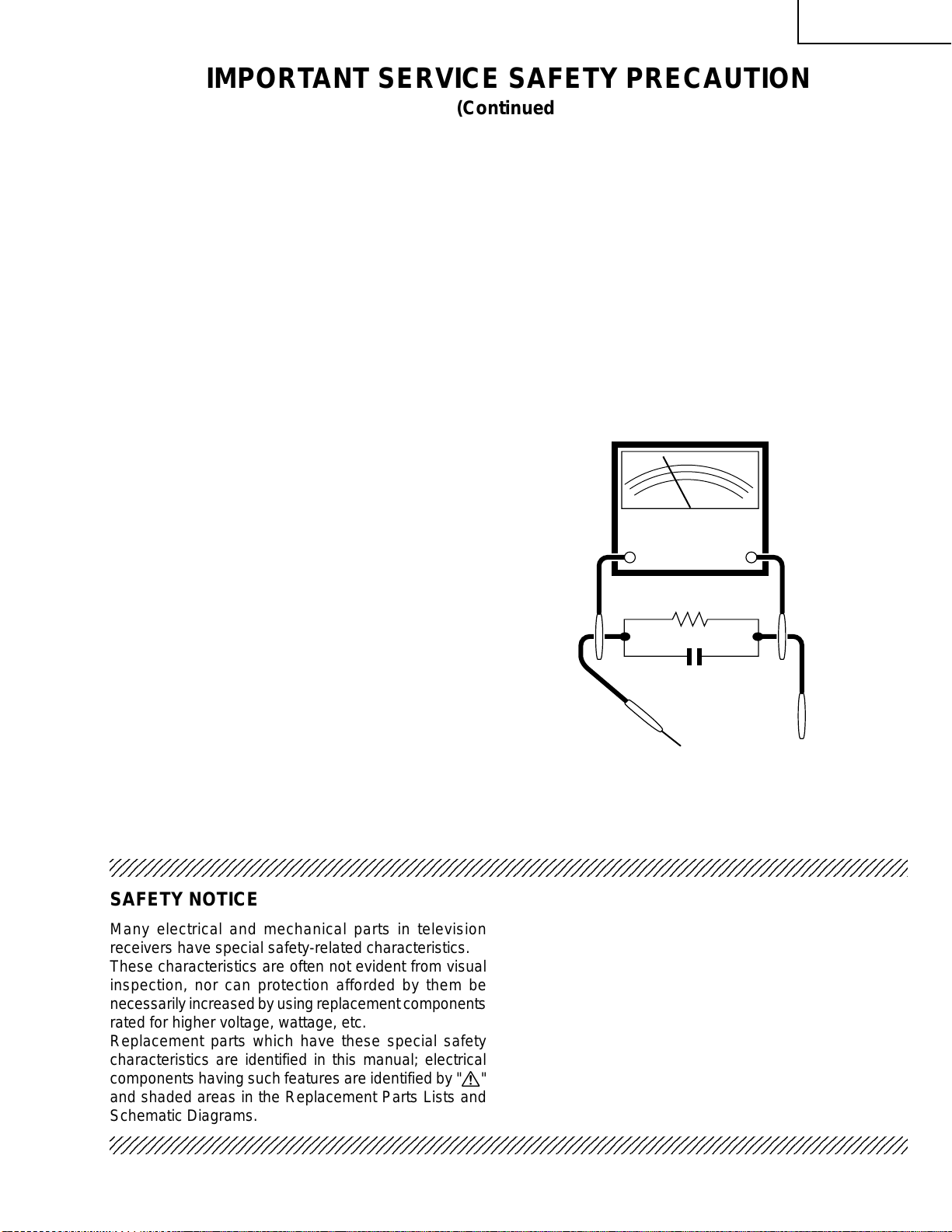
REPARATION DU SYSTEMEA HAUTE TEN-
SION ET DU TUBE-IMAGE
Lors de la réparation de ce systéme,
supprimer la charge statique en branchant
une résistance de 10 kΩen série avec un fil
isolé (comme une sonde d'essai) entre la
mise à la terre du tube-image et le fil
d'anodel.(Le cordend'alimentation doitêtre
retiré de la prise murale.)
1. Le tube image dans ce récepteur emploie une
protection intégrée contre l'implosion.
2. Par mesure de sécurité, changer le tube-image pour
un tube du même numéro de type.
3. Ne pas lever le tube-image par son col.
4. Nemanipuler le tube-imagequ'enporantdes lunettes
incassables et qu'après avoir déchargé totalement
la haute tension.
LIMITES DES RADIATIONS X ET DE LA
HAUTE TENSION
1. Tout le personnel réparateur doit être instruit des
instructions et procédés relatifs aux radiations X.
Le tube-image, seule source de rayons X dons les
téleviseurs transistorisés, n'émet pourtant pas de
rayonsmesurables sila haute tension est maintenue
à un niveau préconisé dans la section "Vérification
de la haute tension".
C'estseulementquandla haute tensionestexcessive
que les rayons X peuvent entrer dans l'enveloppe du
tube-image y compris le conducteur de verre. Il est
important de maintenir la haute tension en-dessous
du niveau spécifié.
2. Il est essentiel que le réparateur ait sous la main un
voltmètreàhautetensionqui doit être périodiquement
étalonné.
3. La haute tension doit toujours être maintenue à la
valeur de régime -et pas plus haute. L'opération à
des tensions plus élevées peut entraîner une panne
du tube-image ou du circuit à haute tension et, dans
certaines conditions, peut entraîner une radiation
dépassant les niveaux préscrits.
4. Quand le régulateur à haute tension fonctionne
correctement, il n'y a aucun problème de radiation
X. Chaque fois qu'un châssis couleurs est réparé, la
luminosité doit être examinée bout en contrôlant la
haute tension à l'aide d'un voltmètre pour s'assurer
que la haute tension ne dépasse pas la valeur
spécifiée et qu'elle soit correctement réglée.
5. Nepas utiliseruntube-image autreque celui spécifié
et ne pas effectuer de modifications déconseillées
du circuit à haute tension.
6. Lors de la recherche des pannes et des mesures
d'essai sur un récepteur qui présente une haute
tension excessive, éviter de s'approcher inutilement
du récepteur.
Ne pas faire fonctionner le récepteur plus longtemps
que nécessaire pour localiser la cause de la tension
excessive.

5
27N-S100, 27N-S180
CN27S10/14/18
VERIFICATIONS CONTRE L'INCEN-DIE ET
LE CHOC ELECTRIQUE
Avant de rendre le récepteur à l'utilisateur, effectuer
les vérifications suivantes.
12345678901234567890123456789012123456789012345678901234567890121234567890123456789012345678901212
1
234567890123456789012345678901212345678901234567890123456789012123456789012345678901234567890121
2
12345678901234567890123456789012123456789012345678901234567890121234567890123456789012345678901212
12345678901234567890123456789012123456789012345678901234567890121234567890123456789012345678901212
1
234567890123456789012345678901212345678901234567890123456789012123456789012345678901234567890121
2
12345678901234567890123456789012123456789012345678901234567890121234567890123456789012345678901212
AVIS POUR LA SECURITE
Denombreusespièces,électriques et mécaniques,dans
lestéléviseursprésentent descaractéristiquesspéciales
relativesà la sécurité,qui ne sontsouvent pasévidentes
à vue. Le degré de protection ne peut pas être
nécessairement augmentée en utilisant des pièces de
remplacement étalonnées pour haute tension,
puissance, etc.
Les pièces de remplacement qui présentent ces
caractéristiques sont identifiées dans ce manuel; les
pièces électriques qui présentent ces particularités sont
PRECAUTIONS A PRENDRE LORS DE LA REPARATION
(Suite)
1. Inspectertous les faisceauxde câblespours'assurer
queles fils ne soient paspincés ouqu'un outilne soit
pas placé entre le châssis et les autres pièces
métalliques du récepteur.
2. Inspecter tous les dispositifs de protection comme
les boutons de commande non-métalliques, les
isolants,ledosdu coffret,les couvercles oublindages
de réglage et de compartiment, les réseaux de
résistance-capacité, les isolateurs mécaniques, etc.
3. S'assurer qu'il n'y ait pas de danger d'électrocution
en vérifiant la fuite de courant, de la facon suivante:
•Brancherle cordon d'alimentationdirectem-entà une
prise de courant de 120V. (Ne pas utiliser de
transformateur d'isolation pour cet essai).
•Al'aidede deux filsàpinces,brancher unerésistance
de1,5kΩ10 watts enparallèleavecun condensateur
de0,15µFen série avectouteslespièces métalliques
exposées du coffret et une terre connue comme une
conduite électrique ou une prise de terre branchée à
la terre.
•Utiliser un voltmètre CA d'une sensibilité d'au moins
5000Ω/Vpour mesurer lachute de tensionen travers
de la résistance.
TO EXPOSED
METAL PARTS CONNECT TO
KNOWN EARTH
GROUND
•Toucheravec lasonde d'essai lespièces métalliques
exposées qui présentent une voie de retour au
châssis (antenne, coffret métallique, tête des vis,
arbres de commande et des boutons, écusson, etc.)
et mesurer la chute de tension CA en-travers de la
résistance. Toutes les vérifications doivent être
refaites après avoir inversé la fiche du cordon
d'alimentation.(Si nécessaire, uneprise d'adpatation
nonpolariséepeutêtreutiliséedansle but de terminer
ces vérifications.)
Tous les courants mesurés ne doivent pas dépasser
0,5 mA.
Dans le cas contraire, il y a une possibilité de choc
électrique qui doit être supprimée avant de rendre le
récepteur au client.
identifiées par la marque " å" et hachurées dans la
liste des pièces de remplacement et les diagrammes
schématiques.
Pour assurer la protection, ces pièces doivent être
identiques à celles utilisées dans le circuit d'origine.
L'utilisation de pièces qui n'ont pas les mêmes
caractéristiques que les pièces recommandées par
l'usine, indiquées dans ce manuel, peut provoquer des
électrocutions, incendies, radiations X ou autres
accidents.
Voltmètre CA
1.5k ohm
10W
BRANCHER A UNE
TERRE CONNUE
AUX PIECES
METALLIQUES
EXPOSEES
0.15µF
SONDE D'ESSAI

6
27N-S100, 27N-S180
CN27S10/14/18
LOCATION OF USER'S CONTROL
Front Panel
Basic Remote Control Functions
POWER
Press →On.
Press again →Off.
REMOTE KEYPAD
Accesses any channel from keypad.
FLASHBACK
Returns to previous channel.
PERSONAL PREFERENCE
With the Personal Preference buttons,
you can program your favorite
programs by using the four categories
A, B, C and D. The channels can be
accessed quickly by using these
buttons.
VOLUME UP/DOWN
(+) Increases sound.
(–) Decreases sound.
• In menu mode, changes or selects
the TV adjustments.
MENU
Press →Accesses MAIN MENU.
Press again →Exits MAIN MENU.
TV-CATV MODE SELECT SWITCH
In TV position, sends power and
channel select commands (Channel
up/down and RandomAccess buttons)
to the TV.
In CATV position, sends power and
channel select commands to a cable
TV converter.
VCR CONTROL
Infrared Transmitter Window
DISPLAY
Press→Displays receivingchannel for
four seconds.
Press again →Removes display.
• Temporarily displays receiving
channel when in Closed Caption
mode.
INPUT
Press →Switch to external video
INPUT 1 mode.
Pressagain →Switch toexternal video
INPUT 2 mode.
Pressthree times→Switch back tothe
original TV mode.
ENTER
Used in some instances where a VCR
or Cable Converter Box requires an
“enter” command after selecting
channels, when using the REMOTE
KEYPAD button.
CHANNEL UP/DOWN
( ) Selects next higher channel.
( ) Selects next lower channel.
• Moves the “ ” mark of the MENU
screens.
MUTE
Press →Mutes sound.
Press again →Restores sound.
• CLOSED CAPTION appears when
sound is muted.
• The above shaded buttons on the Remote Control glow in the dark. To use the glow-in-the-dark display on the
remote control, place it under a fluorescent light or other lighting.
• The phosphorescent material contains no radioactive or toxic material, so it is safe to use.
• The degree of illumination will vary depending on the strength of lighting used.
• The degree of illumination will decrease with time and depending on the temperature.
• The time needed to charge the phosphorescent display will vary depending on the surrounding lighting.
• Sunlight and fluorescent lighting are the most effective when charging the display.
NOTE:
+
'
"
POWER
Press →On.
Press again →Off.
VOLUME UP/DOWN
(+) Increases sound.
(–) Decreases sound. SENSOR AREA FOR
REMOTE CONTROL
'
"
CHANNEL UP/DOWN
( ) Selects next higher channel.
( ) Selects next lower channel.
• Press both at same time to
access MAIN MENU Screen.
VIDEO/AUDIO TERMINALS
(VIDEO/AUDIO terminals are also
provided on the rear.)
IN 2

7
27N-S100, 27N-S180
CN27S10/14/18
CIRCUIT PROTECTION
The receiver is protected by a 4.0A fuse (F701),
mounted on PWB-A, wired into one side of the AC
line input.
X-RADIATION PROTECTOR CIRCUIT TEST
After service has been performed on the horizontal
deflection system, high voltage system, B+ system,
test the X-Radiation protection circuit to ascertain
proper operation as follows:
1. Apply 120V AC using a variac transformer for
accurate input voltage.
2. Allow for warm up and adjust all customer controls
for normal picture and sound.
3. Receive a good local channel.
4. Connect a digital voltmeter to TP653 and make sure
that the voltmeter reads 11.2 ± 0.6V.
5. Apply external 13.8V DC at TP653 by using an
external DC supply, TV must shut off.
6. To reset the protector, unplug the AC cord and make
ashort circuit betweenTP651andTP652.Nowmake
sure that normal picture appears on the screen.
7. If the operation of the horizontal oscillator does not
stop in step 5, the circuit must be repaired before the
set is returned to the customer.
HIGH VOLTAGE CHECK
High voltage is not adjustable but must be checked
to verify that the receiver is operating within safe
and efficient design limitations as specified checks
should be as follows:
1. Connect an accurate high voltage meter between
ground and anode of picture tube.
2. Operate receiver for at least 15 minutes at 120V AC
linevoltage,withastrongairsignalor a properly tuned
in test signal.
3. Enter the service mode and select the service
adjustment "S19" and Bus data "01" (Y-mute on).
4. Thevoltage shouldbeapproximately, 28.7kV(atzero
beam).
Ifacorrectreadingcannotbe obtained, check circuitry
formalfunctioningcomponents. Afterthe voltage test,
make Y-mute off to the normal mode.
INSTALLATION AND SERVICE INSTRUCTIONS
Note: (1)When performing any adjustments to resistor controls and transformers use non-metallic
screwdrivers or TV alignment tools.
(2)Before performing adjustments, the TV set must be on at least 15 minutes.

8
27N-S100, 27N-S180
CN27S10/14/18
Figure A.
S01 02
CHANNEL
SERVICE ADJUSTMENT NUMBER
DATA NUMBER
S01 D:00
For adjustments of this model, the bus data is converted to various analog signals by the D/A converter
circuit.
Note: There are still a few analog adjustments in this series such as focus and master screen voltage.
Follow the steps below whenever the service adjustment is required. See "Table-B" to determine, if serv-
ice adjustments are required.
1. Service mode
Before putting unit into the service mode, check that
customer adjustments are in the normal mode. Use
the reset function in the video adjustment menu to
ensure customer controls are in their proper (reset)
position.
2. Service number selection
Once in the service mode, press the Ch-up or Ch-
down button on the remote controller or at the set.
The service adjustment number will vary in
increments of one, from "S01" to "M05". Select the
item you wish to adjust.
3. Data number selection
Press the Vol-up or down button to adjust the data
number.
To enter the service mode and exit serv-
ice mode.
While pressing the Vol-up and Ch-up buttons at the
sametime, plug the AC cord into a wall socket.
Now the TV set is switched on and enters the service
mode.
To exit the service mode, turn the television off by
pressing the power button.
55(085)

9
27N-S100, 27N-S180
CN27S10/14/18
SERVICE
NUMBER DATA ADJUSTMENT CONTENTS
ADJUSTMENT ITEM RANGE
INITIAL VALUE
S01 PICTURE 55 00-7F
S02 TINT 46 00-7F
S03 COLOR 32 00-7F
S04 BRIGHTNESS 40 00-7F
S05 SHARPNESS 28 00-3F Must be set to "28"
S06 VERTICAL PHASE 00 00-07 Must be set to "00"
S07 HORIZONTAL PHASE 12 00-1F
S08 RF-AGC 23 00-3F
S09 VERTICALAMP 20 00-3F
S10 PIF VCO 2C 00-7F
S11 R CUT-OFF 00 00-FF
S12 G CUT -OFF 00 00-FF
S13 B CUT-OFF 00 00-FF
S14 G GAIN 7F 00-FF
S15 B GAIN 7F 00-FF
S16 TRAP 00 00 or 01 Must be set to "00"
S17 BALANCE 20 00-3F Must be set to "20"
S18 C.C.POSITION 17 00-7F
S19 MUTE 00 00,01,03 "00"=Normal, "01"=No-Y, "03"=No Vertical
S20 ENERGY SAVE OFFSET 20 00-3F Must be set to "23"
S21 D.D.E. OFFSET 03 00-1F Must be set to "03"
S22 OSD SETUP 00 00-03 Must be set to "00"
S23 TUNER SETUP 00 00, 01 Must be set to "00"
OP1 OPTION1 (Set to each mode) 00 00-FF "B3"=27N-S100, "B7"=27N-S180,
"A7"=CN27S10, "A7"=CN27S14, "A7"=CN27S18
OP2 OPTION2 00 00-FF "A7"=27N-S100, "A7"=27N-S180,
"07"=CN27S10, "A7"=CN27S14, "A7"=CN27S18
M01 INPUT LEVEL 0A 00-0F
M02 ST VCO 20 00-3F
M03 FILTER 1C 00-3F
M04 WIDE BAND 20 00-3F
M05 SPECTRAL 1B 00-3F
NECESSARY UNNECESSARY
ADJUSTMENT NOTES
PART REPLACED
IC2001
IC2101 X
IC3001 X
CRT X
IC201 X
XData is stored in IC2101.
The adjustment is needed to compensate for characteristics
of parts including IC201 and MTS level (M01).
Holding down both the Vol-up/CH-down buttons on the TV
set in the service mode for more than 2 seconds will
automatically write the above initial values into IC2101. Then
perform a complete adjustment.
Adjust items related to picture tube only.
Adjust items related to MTS only (M01~M05).
Holding down both the Vol-up/CH-down buttons on the TV set at service mode for more than 2 seconds will
automatically write the above initial values into IC2101.
Table - A
Table - B

10
27N-S100, 27N-S180
CN27S10/14/18
SERVICE ADJUSTMENT
VCO Adjustment
1. Connecta digitalvoltmeterbetween pin(44)of IC201
and ground.
2. Receive a good local channel.
3. Enter the service mode and select the service
adjustment "S10".
4. Adjust the data so that digital voltmeter reads 2.2V.
5. Adjustment is completed, remove the voltmeter,
return to "normal" mode.
RF AGC Adjustment
1. Receive a good local channel.
2. Enter the service mode and select the service
adjustment "S08".
3. Set the data value to point where no noise or beat
appears.
4. Select another channel to confirm that no noise or
beat appears.
Note 1 : You will have to come out of the service
mode to select another channel.
Note 2 : Setting thedata to "00"will produceablack
raster.
Screen Adjustment
1. Connect a oscilloscope between TP854 and GND
on the CRT Unit.
2. Receive a good local channel.
3. Enter the service mode and select the service
adjustment "S03" and set the data value to "00" to
set the color level to minimum. (Record original data
code under adjustment "S03" before changing) You
may skip this step, if you selected a B/W picture or
monoscope pattern.
4. Select the service adjustment "S19" and adjust the
data value to "01", this turn off the luminance signal
(Y-mute).
5. Select the service adjustment "S04" and adjust data
valueto obtain2.35 voltson the oscilloscope screen.
6. Adjust the master screen control until the raster
darkens to the point where raster is barely seen.
7. Adjustthe service adjustments"S11"red,"S12"green
and "S13" blue to obtain a good grey scale with
normal whites at low brightness level.
8. Select the service adjustment "S19" and reset data
to"00".Select the serviceadjustment"S03" and reset
data to obtain normal color level.
9. Remove oscilloscope, and reset the master screen
control to obtain normal brightness range.
White Balance Adjustment
1. Receive a good local channel.
2. Enter the service mode and select the service
adjustment "S03" and set to "00" (minimum
color)(Record original data code under adjustment
"S03" before changing). "S03" does not have to be
adjusted,if you selectedaB/W pictureormonoscope
pattern.
3. Alternatelyadjustthe service adjustment data of "S14"
and "S15" until a good grey scale with normal whites
is obtained.
4. Select the service adjustment "S03" and adjust data
to obtain normal color level.
Sub-Picture Adjustment
1. Receive a good local channel.
2. Make sure the customer picture control is set to
maximum.
3. Enter the service mode and select the service
adjustment "S01".
4. Adjust the data value to achieve normal contrast
range.
Sub-Tint Adjustment
1. Receive a good local channel.
2. Set customer tint control to center of it's range.
3. Enter the service mode and select the service
adjustment "S02".
4. Adjust "S02" data value to obtain normal flesh tones.
Sub-Color Adjustment
1. Receive a good local channel.
2. Makesure thecustomer color controlis setto center
position .
3. Enterthe service modeandselectservice adjustment
"S03".
4. Adjust "S03" data value to obtain normal color level.

11
27N-S100, 27N-S180
CN27S10/14/18
3.58MHz Trap Adjustment
1. Receive a good local channel.
2. Enter the service mode and select the service
adjustment "S16".
3. This is a two position adjustment, "00" is ON, "01" is
OFF.
4. Models should be adjusted as follows.
Sharpness and Audio Balance Adjust-
ments
1. Receive a good local channel.
2. Enter the service mode and select the service
adjustments "S05" for sharpness and "S17" for
balance.
»Sharpness Adjustment
3. Adjust data value to "28"(center of data range) for
sharpness adjustment.
»Audio Balance Adjustment
4. Adjust data value to "20"(center of data range) for
audio balance adjustment.
Energy save offset Adjustment
1. Enter the service mode and select the service
adjustment "S20".
2. Adjust data value to "23".
Note : This position is used to preset the level for the
energy save function.
Other Adjustments
1. Enter the service mode.
2. Adjust the following data values as listed below.
Sub-Brightness Adjustment
1. Receive a good local channel.
2. Make sure the customer brightness control is set to
center position.
3. Enter the service mode and select the service
adjustment "S04".
4. Adjust "S04" data value to obtain normal brightness
level.
Vertical-Size Adjustment
1. Receive a good local channel.
2. Enter the service mode and select the service
adjustment "S09".
3. While observing the top and bottom of the screen,
adjust "S09" data value to proper vertical size.
Vertical Phase Adjustment
1. Enter the service mode and select the service
adjustment "S06".
2. Adjust data value to "00".
Note: Thismust beset "00" when changeddata retrace
line will appear.
Horizontal Position Adjustment
1. Receive a good local channel.
2. Enter the service mode and select the service
adjustment "S07".
3. Adjust "S07" data value so that picture is centered.
Caption Position Adjustment (Horizontal)
1. Receive a good local channel.
2. Enter the service mode and select the service
adjustment "S18".
3. A black text box appears on the screen. (see Figure
B. below)
4. Adjust "S18" data value so that text box is positioned
in the center of the screen.
MODEL "S16"
27N-S100 01
27N-S180 01
CN27S10 00
CN27S14 01
CN27S18 01
Figure B.
S21 "03" DDE OFFSET
S22 "00" OSD SETUP
S23 "00" TUNER SETUP

12
27N-S100, 27N-S180
CN27S10/14/18
MTS ADJUSTMENT
MTS Level Adjustment
1. Feed the following monaural signal to pin (14) of
IC3001.
Monaural signal : 300Hz, 245mVrms
2. Connect the rms voltmeter to pin (39) of IC3001.
3. Enter the service mode and select the service
adjustment "M01".
4. Adjust the data so that the rms voltmeter reads.
Spec.: 490 ±10mVrms.
MTS VCO Adjustment
1. Keep the unit in no-signal state.
2. Connectthe frequencycounter to pin (39) of IC3001.
3. Connect a capacitor (100µF, 50V) in between
positive(+) side of C3005 and ground.
4. Enter the service mode and select the service
adjustment "M02"
5. Adjust the data so that the frequency counter reads.
Spec.: 62.94 ±0.75kHz.
Filter Adjustment
1. Feed the following stereo pilot signal to pin (14) of
IC3001 .
Stereo pilot signal: 9.4kHz, 600mVrms.
2. Enter the service mode and select the service
adjustment "M03".
3. Adjust the data at the point where "OK" appears on
the screen. The "OK" represents the approximate
center of the adjustable range of the data.
Separation Adjustment
1. Connect the rms voltmeter to pin (39) of IC3001.
2. Receive the following composite stereo signal 1.
Composite stereo signal: 30% modulation, left
channel only, noise reduction on, 300Hz
3. Enter the service mode and select the service
adjustment "M04".
4. Adjust the data until the AC voltage reading of the
rms voltmeter is minimum.
5. Receive the following composite stereo signal 2.
Stereo signal: 30% modulation, left channel only,
noise reduction on, 3kHz
6. Enter the service mode and select the service
adjustment "M05".
7. Adjust the data until the AC voltage reading of the
rms voltmeter is minimum.
8. Take the above steps 1 thru 8 again for fine
adjustment.

13
27N-S100, 27N-S180
CN27S10/14/18
1716 1918151413121110
CHASSIS LAYOUT
654321
A
B
C
D
E
F
G
H
(27N-S100, CN27S14)
PWB-K
(27N-S180, CN27S18)
PWB-K
PWB-B
PWB-H
PWB-A

14
27N-S100, 27N-S180
CN27S10/14/18
87109654321
A
B
C
D
E
F
G
H
MODEL 27N-S100 BLOCK DIAGRAM
654321
A
B
C
D
E
F
G
H

15
27N-S100, 27N-S180
CN27S10/14/18
1716 1918151413121110
MODELS 27N-S180, CN27S18 BLOCK DIAGRAM
654321
A
B
C
D
E
F
G
H

16
27N-S100, 27N-S180
CN27S10/14/18
87109654321
A
B
C
D
E
F
G
H
MODEL CN27S10 BLOCK DIAGRAM
654321
A
B
C
D
E
F
G
H

17
27N-S100, 27N-S180
CN27S10/14/18
1716 1918151413121110
654321
A
B
C
D
E
F
G
H
MODEL CN27S14 BLOCK DIAGRAM

18
27N-S100, 27N-S180
CN27S10/14/18
87109654321
A
B
C
D
E
F
G
H
DESCRIPTION OF SCHEMATIC DIAGRAM
NOTES:
1. The unit of resistance "ohm" is omitted.
(K=k
Ω
=1000
Ω
, M=M
Ω
)
2. All resistors are 1/8 watt, unless otherwise noted.
3. All capacitors are µ F, unless otherwise noted.
(P=pF=µµF)
4. (G) indicates ±2% tolerance may be used.
5. indicates line isolated ground.
VOLTAGE MEASUREMENT CONDITIONS:
1. All DC voltages are measured with DVM connected
between points indicated and chassis ground, line
voltagesetat 120VACandallcontrols set for normal
picture unless otherwise indicated.
2. All voltages measured with 1000µ V B & W or Color
signal.
WAVEFORM MEASUREMENT CONDITIONS:
1. Photographs taken on a standard gated color bar
signal, the tint setting adjusted for proper color. The
wave shapes at the red, green and blue cathodes of
the picture tube depend on the tint, color level and
picture control.
2.
indicates waveform check points (See chart,
waveforms are measured from point indicated to
chassis ground.)
å
AND SHADED ( ) COMPONENTS
= SAFETY RELATED PARTS.
'
MARK= X-RAY RELATED PARTS.
DRGANNES MARQUES
å
ET HACHRES ( ):
PIECES RELATIVES A LA SECURITE.
MARQUE
'
: PIECS RELATIVE AUX RAYONS X.
This circuit diagram is a standard one, printed circuits
may be subject to change for product improvement
without prior notice.
WAVE FORMS

19
27N-S100, 27N-S180
CN27S10/14/18
1716 1918151413121110
654321
A
B
C
D
E
F
G
H
SCHEMATIC DIAGRAM: CRT and FRONT AV Units

21
27N-S100, 27N-S180
CN27S10/14/18
20
121110987654321
A
B
C
D
E
F
G
H
MODEL 27N-S100 SCHEMATIC DIAGRAM: MAIN-1 Unit
This manual suits for next models
4
Table of contents
Other Sharp TV manuals

Sharp
Sharp 50BJ2KE User manual

Sharp
Sharp Aquos LC-52D82U User manual

Sharp
Sharp 21K-FD1SA User manual

Sharp
Sharp 28LF-96EC User manual

Sharp
Sharp 66GF-63H User manual

Sharp
Sharp 21J-FG1RU User manual

Sharp
Sharp 21AXS500 User manual

Sharp
Sharp LC-20SH3H User manual

Sharp
Sharp AQUOS LC-46D43U User manual

Sharp
Sharp SX51LF7 User manual

Sharp
Sharp AQUOS 8T-C60DW1X Manual

Sharp
Sharp 20AG2-SMK3 User manual

Sharp
Sharp Aquos 2T-C50BG1X User manual

Sharp
Sharp DV-1600 Series User manual

Sharp
Sharp LC-32LE40E User manual

Sharp
Sharp CX34K3 User manual

Sharp
Sharp Aquos LC-60LE631M User manual

Sharp
Sharp LC-48CFE4042E User manual

Sharp
Sharp AQUOS LC-70UX500H User manual

Sharp
Sharp cx68n5 User manual