6
VC-MH705HM/LM
VC-MH815HM/LM,MH85HM
VC-MH715HM,MH835HM
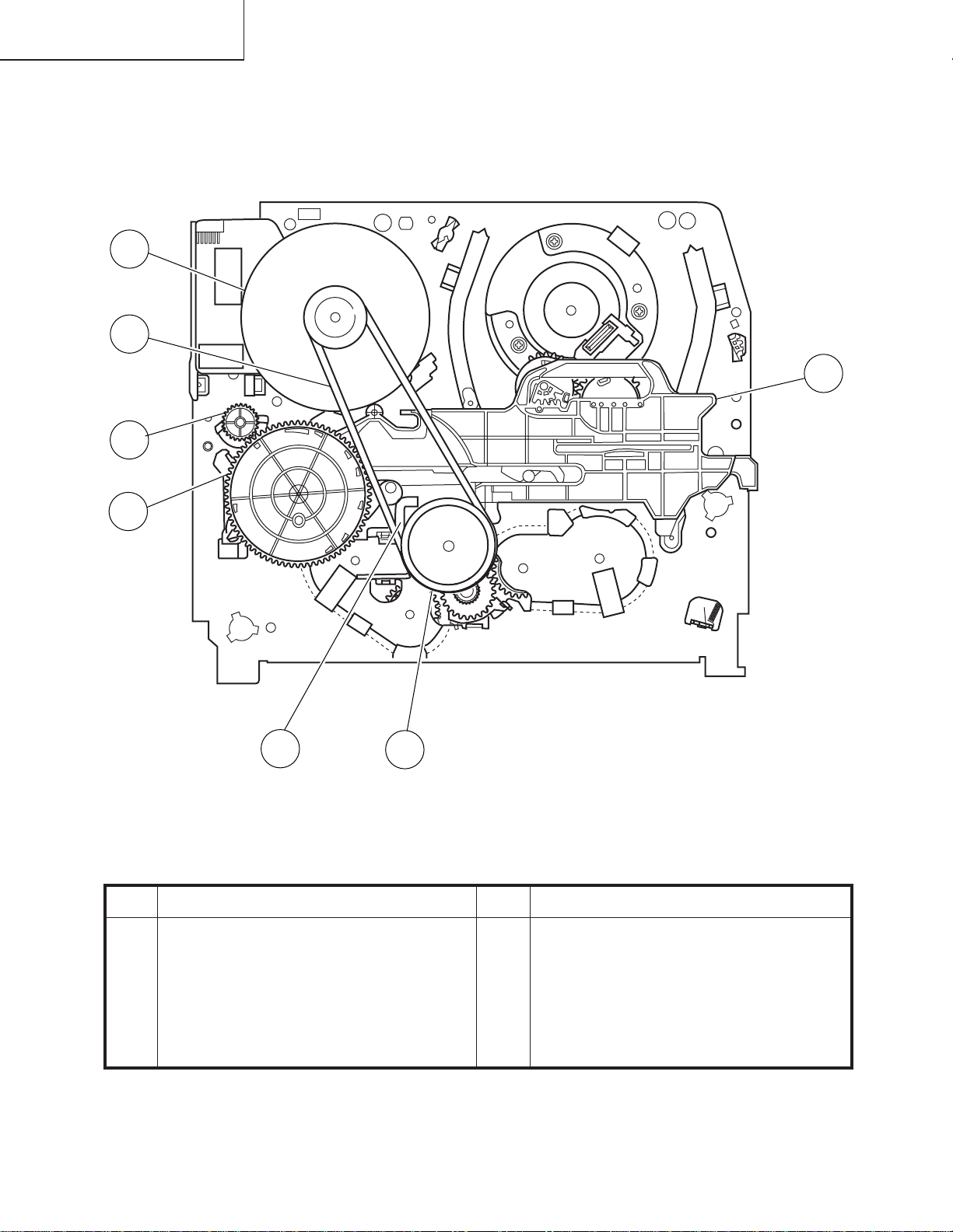
Pinch Drive Cam
Synchro Gear Master cam
Main Chassis
Drive Lever
2-2 CARES WHEN REASSEMBLING
INSTALLING THE CASSETTE HOUSING
When the cassette housing is installed on the mechanism,
the initial setting is essential condition.
Therearetwoinitialsettingmethods,namelyelectricaland
mechanical.
1. Electrical initial setting
So as to perform initial setting of mechanism execute the
Step1ofInstallationofcassettehousing.Afterascertaining
the return to the initial setting position install the cassette
housing. (Conditions: When mechanism and PWB have
been installed)
2. Mechanical initial setting
•Rotatethewormgearbypushingtheflangemanuallyuntil
return to initial position.
•When apply power supply to rotate the loading motor,
please remove/unsolder at least one terminal wire.
•If voltage applied to loading motor without diconnecting
the terminal wire, there is a possibility the capstan motor
IC will damage.
•The maximum applied voltage is 9V. If more than 9V,
there is apossibility the mechanism will damage.
•After ascertaining the return to the initial set position
installthecassettehousinginthespecifiedposition.(This
method is applied only for the mechanism.)
Rotate the flange of worm gear by using thin stick.
CW • • • Loading direction
CCW • • • Ejection direction
Note:
Be careful not to damage the gear of worm gear and
worm wheel gear. It miight cause a strange sound.
AH CONNECTOR
AE CONNECTOR
END SENSOR
END TIP SW
AA CONNECTOR
AD CONNECTOR
MODE SW
START SENSOR
VC-A50 only
AC CORD
90°
180°
270°
0°
MASTER CAM POSITION
This positioning hole
should be at front side.
INSTALLING THE MECHANISM ON PWB
Lower vertically the mechanism, paying attention to the
mechanism edge mode SW position, (Set the mode SW
position to 270° and make sure the master cam position
hole also in 270° position) and install the mechanism with
due care so that the parts are not damaged.
* Please make sure to insert correctly.
If not, strange moving will occur and will couse mecha-
nism damage.
PARTS WHICH NEED PARTICULAR CARE
When installing the mechanism chassis on the PWB unit,
take care so as to prevent deformation due to contact of
mechanism chassis with REC TIP SW.
www.freeservicemanuals.info
Digitized in Heiloo the Netherlands