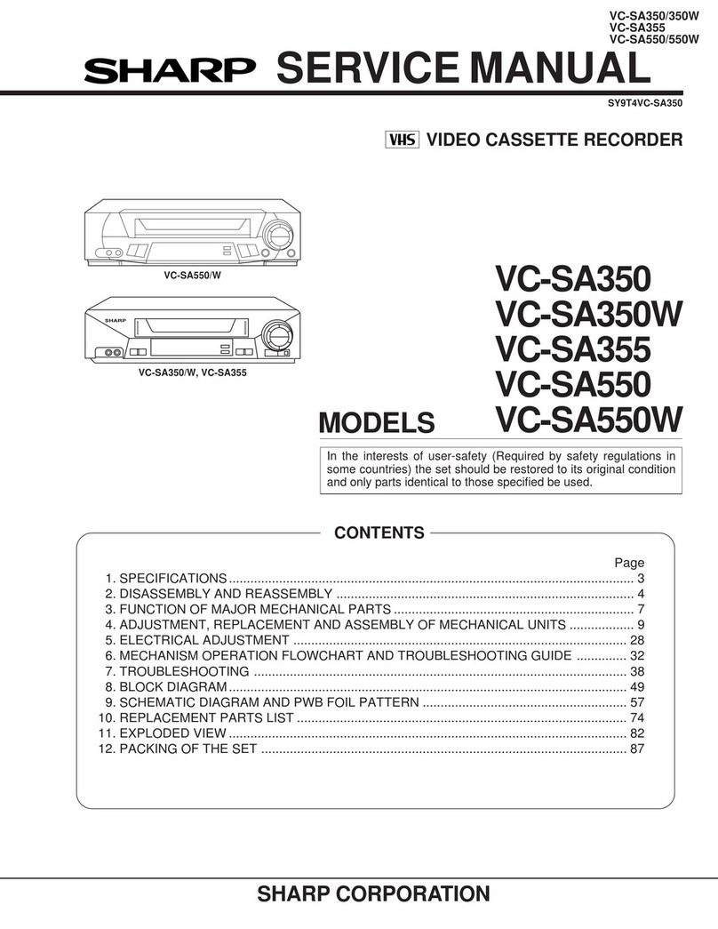
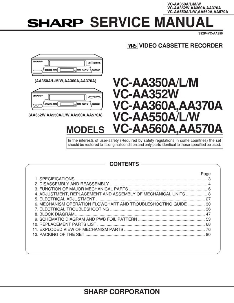
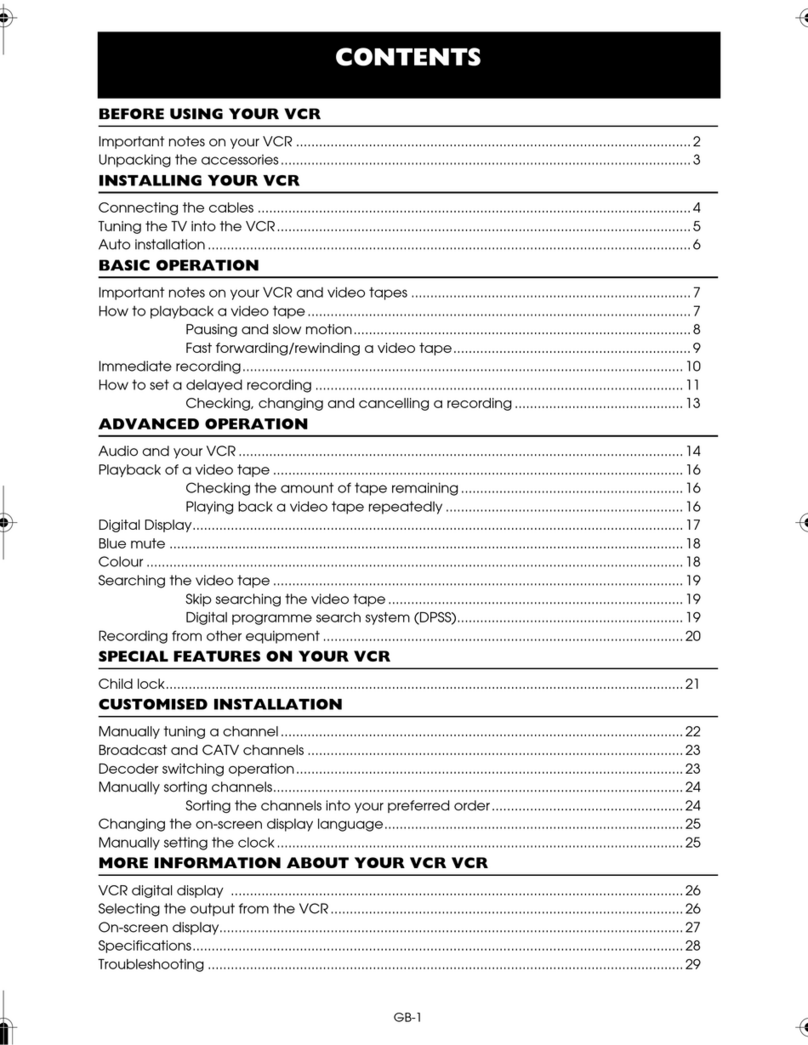
Sharp VC-A598U User manual

VC-A598U/H995U/H996U
-H997U/H9977U/H998U
1
SERVICEMANUAL
This document has been published to be used for
after sales service only.
Thecontentsaresubjecttochangewithoutnotice.
SHARP CORPORATION
VIDEO CASSETTE RECORDER
MODELS
In the interests of user-safety (Required by safety regulations in some
countries) the set should be restored to its original condition and only parts
identical to those specified be used.
VC-A598U/H995U/
H996U/H997U/
H9977U/H998U
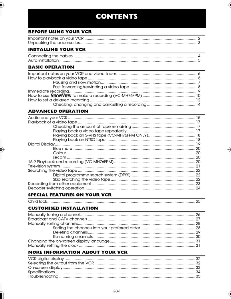
CONTENTS
VC-A598U/H995U/H996U/H998U ..... Models for U.S.A.
VC-H997U/H9977U/H998U ............... Models for CANADA
(VC-A598U/H995U/H996U/H997U)
(VC-H9977U/H998U)
S39D6VC-A598U
Page
1. GENERAL INFORMATION .............................. 5
1-1 FEATURES.................................................5
1-2 SPECIFICATIONS ..................................... 5
1-3 LOCATION OF MAJOR COMPONENTS
AND CONTROL ......................................... 6
2. DISASSEMBLY AND REASSEMBLY .............. 7
2-1 DISASSEMBLY OF MAJOR BLOCKS....... 7
2-2 DISASSEMBLING THE MECHANISM/
MAIN PWB ASSEMBLY............................. 8
2-3 CARES WHEN REASSEMBLING.............. 9
3. FUNCTION OF MAJOR MECHANICAL
PARTS ............................................................10
4. ADJUSTMENT, REPLACEMENT AND
ASSEMBLY OF MECHANICAL UNITS.......... 12
4-1 MECHANISM CONFIRMATION
ADJUSTMENT JIG .................................. 12
5. ELECTRICAL ADJUSTMENT ........................ 31
5-1 ADJUSTMENT OF HEAD SWITCHING
POINT .......................................................32
Page
5-2 ADJUSTMENT OF FV (False Vertical Sync)
OF STILL PICTURE................................. 32
5-3 CHECKING OF OFF TRACK................... 32
5-4 ADJUSTMENT OF SIF-INPUT LEVEL .... 33
5-5 ADJUSTMENT OF STEREO
SEPARATION ...........................................33
INITIAL JUMPER STTING METHOD............. 33
6. MECHANISM OPERATION FLOWCHART
AND TROUBLESHOOTING GUIDE .............. 34
7. TROUBLESHOOTING ................................... 40
8. BLOCK DIAGRAM ..........................................51
9. SCHEMATIC DIAGRAM AND PWB FOIL
PATTERN .......................................................59
10.PARTS LIST....................................................75
11.EXPLODED VIEW OF MECHANICAL
PARTS ............................................................84
12.PACKING OF THE SET ................................. 89

VC-A598U/H995U/H996U
-H997U/H9977U/H998U
2
IMPORTANT SERVICE NOTES
WARNING :TOREDUCETHERISKOFFIREORELEC-
TRIC SHOCK, DO NOT EXPOSE THIS AP-
PLIANCE TO RAIN OR MOISTURE.
RISK OF ELECTRIC SHOCK
DO NOT OPEN
CAUTION
CAUTION: TO REDUCE THE RISK OF ELECTRIC SHOCK. DO
NOT REMOVE COVER. NO USER-SERVICEABLE
PARTS INSIDE. REFER SERVICING TO QUALIFIED
SERVICE PERSONNEL.
This symbol warns the user of uninsulated voltage
withintheunitthatcancausedangerouselectricshocks.
This symbol alerts the user that there are important
operatingandmaintenanceinstructionsintheliterature
accompanying this unit.
This symbol mark means fast operating fuse.
For continued protection against risk of fire, replace
only with same type fuse F901 (3.0A, 125V).
CAUTION:
BEFORE RETURNING THE VIDEO CASSETTE
RECORDER
Beforereturning thevideocassette recordertothe user,
perform the following safety checks.
1. Inspect all lead dress to make certain that leads are
not pinched or that hardware is not lodged between
thechassisandothermetalpartsinthevideocassette
recorder.
2. Inspect all protective devices such as non-metallic
control knobs, insulation materials, cabinet backs,
adjustmentandcompartmentcoversorshields,isola-
tion resistor/capacitor networks, mechanical insula-
tors etc.
3. To be sure that no shock hazard exists, check for
current in the following manner.
●Plug the AC line cord directly into a 120 volt AC outlet
(Do not use an isolation transformer for this test).
●Using two clip leads, connect a 1.5k ohm, 10 watt
resistorparalleledbya0.15µFcapacitorinserieswith
all exposed metal cabinet parts and a known earth
ground, such as a water pipe or conduit.
●Use an SSVM or VOM with 1000 ohm per volt, or
higher, sensitivity or measure the AC voltage drop
across the resistor (See Diagram).
●Move the resistor connection to earth exposed metal
part having a return path to the chassis (antenna,
metalcabinet,screwheads,knobsandcontrolshafts,
SSVM
AC SCALE
1.5k ohms.
10W
CONNECT TO
KNOWN EARTH
GROUND
TO EXPOSED
METAL PARTS
0.15 µF
TEST PROBE
etc.) and measure the AC voltage drop across the
resistor. Reverse the AC plug on the set and repeat
AC voltage measurements for each exposed part.
Anyreading of 0.45Vrms(this corresponds to0.3mA
rms AC.) or more is excessive and indicates a poten-
tial shock hazard which must be corrected before
returning the video cassette recorder to the owner.
3.0A 125V

VC-A598U/H995U/H996U
-H997U/H9977U/H998U
3
entrelarésistance.InverserlaficheCA(uneficheintermédiaire
non polarisée doit être utilisée à seule fin de faire ces
vérifications.) sur l’appareil et répéter les mesures de tension
CA pour chaque piéce métallique exposée. Toute lecture de
0,45 Vrms (ceci correspond à 0,3 mArms CA) ou plus est
excessive et signale un danger de choc qui doit être corrigé
avant de rendre le magnétoscope à son utilisateur.
NOTES DE SERVICE IMPORTANTES
ATTENTION: POUR REDUIRE LES RESQUES D'IN-
CENDIE OU DE CHOC ELECTRIQUE,
NE PAS EXPOSER CET APPAREIL A
LA PLUIE OU A L'HUMIDITE.
AVANT DE RENDRE LE MAGNETOSCOPE
Avant de rendre le magnétoscope à l’utilisateur, effectuer les
vérifications de sécurité suivantes.
1. Vérifiertoutes les gaines defilpour être sûr que lesfilsne sont
paspincés ou quelematériel n’est pascoincé entre le châssis
et les autres pièces métalliques dans le magnétoscope.
2. Vérifiertouslesdispositifsdeprotectiontelsquelesboutonsde
commande non métalliques, les matériaux d’isolement, le dos
ducoffret,lescouverclesdecompartimentetajustementoules
boucliers,lesréseauxderésistance/condensateurd’isolement,
Ies isolateurs mécaniques, etc.
3. Pourêtresûrqu’iln’yaaucunrisquedechocélectrique,vérifier
le courant de fuite de la maniére suivante.
●Brancher le cordon d’alimentation secteur directement dans
une prise de courant de 120 volts. (Ne pas utiliser de
transformateur d’isolement pour cet essai).
●Utiliser deux fils à pinces et connecter une résistance de 10
watts 1,5 kohm en parallèle avec un condensateur de 0,15 µF
ensérieavecdespiècesducoffretmétalliqueexposéesetune
masse de terre connue telle qu’un tuyau ou un conduit d’eau.
●Utiliser un VTVM ou VOM avec une sensibilité de 1000 ohms
par volt ou plus ou mesurer la chute de tension CA entre la
résistance (voir diagramme).
●Déposer la connexion de la résistance à toutes les pièces
métalliques exposées ayant un parcours de retour au châssis
(connexionsd’antenne,coffretmétallique,tétesdevis,boutons
etarbresdecommande,etc.)etmesurerlachutedetensionCA
RISQUE DE CHOC ELECTRIQUE
NE PAS OUVRIR
ATTENTION
Ce symbole avertit l'utilisateur que des instructions
importantesrelativesàl'utilisationetàl'entretiensetrouvent
dans le manuel accompagnant l'appareil.
ATTENTION: AFINDEREDUIRELESRISQUESDECHOCELECTRI-
QUE, NE PAS RETIRER LE COUVERCLE, AUCUN
ORGANE INTERNE NE PEUT ETRE REPARE PAR
L'UTILISATEUR. CONFIER L'APPAREIL A UN
DEPANNEUR QUALIFIE.
Ce symbole signale à l'utilisateur la présence d'une
tensionnonisoléeàl'intérieurdel'appareilquipeutêtrela
cause de secousses électriques dangereuses.
PRECAUTION:
Cette marque indique le fusible à action in stantansée.
Pourlaprotection continuecontrelerisque d'incendie,ne
remplacer que par le fusible type F901 (3A, 125V).
0,15 µF
SONDE D'ESSAI
VERS PIECES
METALLIQUES
EXPOSEES
VTVM
ECHELLE CA
1,5 KOHMS
10W
CANNECTER A
UNE MASSE DE
TERRE CONNUE
3A 125V

VC-A598U/H995U/H996U
-H997U/H9977U/H998U
4
PRECAUTIONS IN PART REPLACEMENT
When servicing the unit with power on, be careful to the section marked white all over.
This is the primary power circuit which is live.
When checking the soldering side in the tape travel mode, make sure first that the tape has been loaded and then turn
over the PWB with due care to the primary power circuit.
Make readjustment, if needed after replacement of part, with the mechanism and its PWB in position in the main frame.
(1) Start and end sensors: Q701 and Q702
Insert the sensor’s projection deep into the upper hole of the holder. Referring to the PWB, fix the sensors tight
enough.
(2) Photocoupler: IC901
Refer to the symbol on the PWB and the anode marking of the part.
(3) Cam switches A and B: D708 and D709.
Adjust the notch of the part to the white marker of the symbol on the PWB. Do not allow any looseness.
(4) Take-up and supply sensors: D707 and D706.
Be careful not to confuse the setting direction of the parts in reference to the symbols on the PWB. Do not allow any
looseness.

VC-A598U/H995U/H996U
-H997U/H9977U/H998U
5
1. GENERAL INFORMATION
1-1 FEATURES
1) Recording system Format: VHS NTSC Standard
Luminance signal: FM recording
Chroma signal: Low frequency converted direct recording
Color system: NTSC
Number of video head: 4
Tape speed: (SP) 33.35 mm/sec
(LP) 16.67 mm/sec
(EP) 11.12 mm/sec
2) Video signal Input level: 0.5 ~ 2.0 Vp-p, 75 ohm unbalanced
Output level: 1.0 Vp-p, 75 ohm unbalanced
Horizontal resolusion: 220 lines (SP mode)
Signal to noise ratio: 45dB (SP mode)
3) Audio signal Input level: – 8 dBs (309mVrms, 47k ohm)
Output level: – 8 dBs (309mVrms, 1k ohm)
Frequency response: 80Hz ~ 10kHz (SP mode linear)
Signal to noise ratio: 43dB (SP mode linear)
Hi-Fi dynamic range: 90dB
HI-Fi Frequency response: 20Hz ~ 20kHz
Hi-Fi Wow and flutter: 0.005% max. with T-120 tape
4) Receiving channel VHF: Channels 2 ~ 13
UHF: Channels 14 ~ 69
CATV: Channels A-8, A-5 ~ W + 84
Antenna Input Impedance: 75 ohm
5) Misc. Fast forward /Rewind time: Approximate 54 second with T-120 cassette
Power source: 120 V AC, 60 Hz
Power consumption: 20 W
Allowable ambient temperature: with T-120 tape 5°C to 40°C (41°F to 104°F)
Operating humidity: below 80% RH
Dimensions: 360 (W), 92 (H), 256 (D) mm(14-3/16, 3-5/8, 10-5/64 inch)(VC-A598U/H995U)
360 (W), 92 (H), 256 (D) mm(14-3/16, 3-5/8, 10-5/64 inch)
(Except VC-A598U/H995U)
Weight: 2.8 kg (6.17 lbs)
Accessories included: 75 ohm coaxial cable, Operation manual, Registration card
Infrared remote control, Dry Battery (2 pcs.)
Note: Specifications may be changed for improvement without notice.
1-2 SPECIFICATIONS
• High speed FF/REW (*400)
• EZ Set Up
• S-VHS Quasi Playback
• Double Azimuth 4-Head
•19
µm Clear Picture System (in EP Mode)
• HQ System for Better Resolusion and color Reproduc-
tion
• 3-Language OSD with Menu Screen Guidance
• 181-ch PLL Quartz Synthesized Random Access Tuner
with Automatic Channel Setting
• Quick Start with Full Loading Mechanism
• 1-Year, 8-Event Programmable Timer
• Simple Recording Timer
• SHARP Super Picture
• 20 seconds Timer Backup
• Field-Still/Variable Slow/Frame Advance
• Real-Time Counter
• Automatic Daylight Saving-Time (D.S.T.)Adjustment
• Blue Screen Noise Elimination
• Automatic Tracking Control System
• Digital Program Search System (DPSS)
• CM Skip Search
• Instant Replay
• Auto Zero Back
• Recorded Section Auto Repeat
• Full Automatic Playback
• Tamper Proof
• Up to 8 Hours of Recording/Playback (T-160)
• Automatic Head Cleaning System
• Built-in Front AV Jacks
• Built-in MTS (Multi-channel TV Sound) Detector
(Hi-Fi Models)
• Built-inShuttleControlSystem(Except VC-A598U/H995U)
• VCR Plus+ Programming System (Except VC-H996U/
H998U)
• VCR Plus+, C3Programming System (VC-H996U/H998U)
• Universal Remote Control: with Light-up Button (VC-
H997U/H9977U),withRemotePagerFunction(VC-H998U)
• Cable Box Channel Control Function/Digital Satellite
Receiver Control Function (VC-H996U/H998U)

VC-A598U/H995U/H996U
-H997U/H9977U/H998U
6
1-3 LOCATION OF MAJOR COMPONENTS AND CONTROL

VC-A598U/H995U/H996U
-H997U/H9977U/H998U
7
4
2
2
B
C
A
B
5
9
6
10
11
7
8
3
3
C
1
A
12
13
5
2. DISASSEMBLY AND REASSEMBLY
2-1 DISASSEMBLY OF MAJOR BLOCKS
TOP CABINET : Remove 2 screws 1.
FRONT PANEL : Remove button 2.
Remove 2 screws 3and 7 clips 4.
OPERATION : Remove 1 screw 5.
PWB
SHIELD ANGLE : Remove1screws6withshieldangle.
MECHANISM/ : Remove 1 screw 7, 1 screw 8, 2
MAIN PWB screws 9, 2 screws 0. Remove 1
screwqwithantennaterminalcover.
Remove 1 screw wwith top cabinet
fix angle.
LOCATOR PWB : Remove 1 screw e.
(VC-H998U)
FRONT PANEL
LOCATOR
PWB
TOPCABINET
SHIELD
ANGLE
H/A SHIELD
TOP
ANTENNA
TERMINAL
COVER
MECHANISM/
MAIN PWB
ASSEMBLY
TOP CABINET
FIX ANGLE
MAIN FRAME
VC-H996U/H997U
/H9977U/H998U
VC-A598U/H995U
OPERATION
PWB
VC-H996U/H997U
/H9977U/H998U
VC-A598U/H995U

VC-A598U/H995U/H996U
-H997U/H9977U/H998U
8
2-2 DISASSEMBLING THE MECHANISM/MAIN PWB ASSEMBLY
1. When removing the mechanism from the main PWB,
removetheantennacover1screw1,andremovethe
antenna cover.
Remove the PWB bottom plate 1 screw 2.
Remove the FFC cable (AA, AD, AH) 3which con-
necting the PWB and the mechanism.
Take out vertically the mechanism so that it does not
damage the adjacent parts.
2. Removing the mechanism and cassette housing.
Remove2screws4fixingthecassettehousingtothe
mechanism, and remove the cassette housing.
MECHANISM CHASSIS
2
1
3
4
CASSETTE
HOUSING
MAIN PWB

VC-A598U/H995U/H996U
-H997U/H9977U/H998U
9
START SENSOR
cassette housing. (Conditions: When mechanism and
PWB have been installed)
2. Mechanical initial setting
Feed the pulley feed gear of loading motor with screw
driver. After ascertaining the return to the initial set posi-
tion (*1) install the cassette housing in the specified
position.(Thismethodisappliedonlyforthemechanism.)
PARTS WHICH NEED PARTICULAR CARE
Wheninstallingthe mechanism chassisonthePWB unit,
take care so as to prevent deformation due to contact of
mechanism chassis with REC TIP SW.
Pulley feed gear
Screwdriver
AE CONNECTOR
AL CONNECTOR
Casecon
drive gear
Drive angle of
cassette housing
REC TIP SW
END SENSOR
AC CONNECTOR
Tilt mark (*1)
INSTALLING THE CASSETTE HOUSING
Whenthecassettehousingisinstalledonthemechanism,
the initial setting is essential condition.
There are two initial setting methods, namely electrical
and mechanical.
1. Electrical initial setting
So as to perform initial setting of mechanism execute the
Step1 of Installationofcassette housing. Afterascertain-
ing the return to the initial setting position (*1) install the
2-3 CARES WHEN REASSEMBLING
INSTALLING THE MECHANISM ON PWB
Lower vertically the mechanism, paying attention to the
mechanism edge, and install the mechanism with due
care so that the parts are not damaged. So as to fix the
mechanismtothemain PWBinstalltwohousings.(Fitthe
antenna cover to one of them. For other, fix the vicinity of
loading motor and solder joint side of main PWB.) Con-
nect again the FFC cable (AA-MH, AD-ME, AH-MH)
between the mechanism and the main PWB.

VC-A598U/H995U/H996U
-H997U/H9977U/H998U
10
3. FUNCTION OF MAJOR MECHANICAL PARTS (TOP VIEW)
No. Function No. Function
1 Full erase head
2 Sup pole base ass’y
3 Tension arm
4 Idler ass’y
5 Pinch drive lever ass’y
6 Supply reel disk
7 Sup main brake
8 Tu main brake
9 Pinch drive cam
10 A/C head ass’y
11 Reverse guide
12 Casecon drive gear
13 Take-up reel disk
14 Pinch roller lever ass’y
1715 10
11
5
9
14
12
8
16
13
4
6
2
7
3
1
18

VC-A598U/H995U/H996U
-H997U/H9977U/H998U
11
FUNCTION OF MAJOR MECHANICAL PARTS (BOTTOM VIEW)
No. Function No. Function
15 Drum ass’y
16 Loading motor
17 Drum drive motor
18 Tu pole base ass’y
19 Slow brake
20 Master cam
21 Capstan D.D. motor
22 Reel belt
23 Clutch lever
24 Limiter pulley ass'y
26 Shifter
26
24
21
22
19
20
12
23

VC-A598U/H995U/H996U
-H997U/H9977U/H998U
12
4. ADJUSTMENT, REPLACEMENT AND ASSEMBLY OF MECHANICAL UNITS
The explanation given below relates to the on-site general service (field service) but it does not relates to the adjustment
and replacement which need high-grade equipment, jigs and skill. For example, the drum assembling, replacement and
adjustment service must be performed by the person who have finished the technical courses.
4-1 MECHANISM CONFIRMATION ADJUSTMENT JIG
So as to perform completely the mechanism adjustment prepare the following special jigs. So as to maintain the initial
performance of the machine the maintenance and check are necessary. Utmost care must be taken so that the tape is
not damaged. If adjustment needs any jig, be sure to use the required jig.
JiGTG1200 CN
JiGMP0001 BY
1. Torque Cassette Meter JiGVHT-063 CZ
No. Jig ltem Part No. Code Configuration Remarks
JiGTG0090 CM
3. Torque Gauge Head JiGTH0006 AW
JiGRH0002 BR
JiGSG2000 BS
JiGSG0300 BF
7. JiGADP003 BK
Tension Gauge
These Jigs are used for checking
and adjusting the reel disk height.
Whenfixinganyparttothethreaded
hole using resin with screw, use the
jig. (Specified torque 5 kg)
Thiscassettetorquemeterisusedforcheck-
ing and adjusting the torque of take-up for
measuring tape back tension.
These Jigs are used for checking
and adjusting the torque of take-up
and supply reel disks.
Master Plane Jig and
Reel Disk Height
Adjusting Jig
Pinch pressing force
measuring jig
This Jig is used with the tension
gauge.Rotarytransformerclearance
adjusting jig.
There are two gauges used for the
tension measurements, 300 g and
2.0kg.
4. Torque Driver JiGTD1200 CB
8.
JiGDRiVER11055
AR
Reverse guide height
adjusting box driver This Jig is used for height adjustment of the
reverse guide (for reverse guide height ad-
justment).
Thesetapes areespecially used for
electrical fine adjustment.
Video Audio HiFi Audio Track
525 Monoscope 7k — 58µm
NTSC Color Bar 1k — 58µm
VROEFZCS BG
OR
VROEFZHS BH
1k
This screwdriver is used for adjusting the
guide roller height.
For X value adjustment
This Jig is used for height
adjustment of the reverse guide.
Guide roller height
adjustment drive
11. JiGDRiVER-6 BM
X value adjustment
gear type screw driver
Reverse Guide Height
Adjusting Jig
10. JiGDRiVERH-4 AP
12. JiGRVGH-F18 BU
2.3k
Black Level
(only SYNC) signal
—19µm
2. Torque Gauge
6.
5.
9. Alignment Tape VROATSV CD

VC-A598U/H995U/H996U
-H997U/H9977U/H998U
13
MAINTENANCE CHECK ITEMS AND EXECUTION TIME
Perform the maintenance with the regular intervals as follows so as to maintain the quality of machine.
Parts Maintained 500
hrs. 1000
hrs. 1500
hrs. 2000
hrs. Remarks
Possible symptom
encountered
Upper and lower drum ass’y
Pinch roller
Capstan D.D. motor
Reel belt
Idler ass’y
Tension band ass’y Screen swaying
Loading motor
Limiter pulley
Supply/take-up main brake levers Tape slack
A/C head
Guide roller ass’y
Sup guide shaft
Reverse guide
Slant pole or pole base
Full erase head Colour and beating
Lateral noises Head
occasionally blocked
Smallsoundorsounddis-
tortion
Poor S/N ratio, no colour
Poorflatnessoftheenvelope
with alignment tape
Cassette not loaded or un-
loaded
No tape running, tape
slack
Cleantape contactpart with
thespecifiedcleaningliquid.
Abnormal rotation or significant vi-
bration requires replacement.
Clean rubber and rubber
contact area with the speci-
fied cleaning liquid.
Cleantapecontactareawith
thespecifiedcleaningliquid.
Notaperunning,unevencol-
our
No tape running, tape
slack, no fast forward/re-
wind motion
No tape running, tape
slack
Replace the roller of the
cleanerwhenitwearsdown.
Just change the AHC roller
assembly for new one.
AHC(Automatic head cleaner)
NOTE: : Part replacement. : Cleaning : Apply grease
<Specified> Cleaning liquid Industrial ethyl alcohol
* Thismechanismdoesnotneedelectricadjustmentwithvariableresistor.Checkparts.Ifanydeviationisfound,clean
or replace parts.

VC-A598U/H995U/H996U
-H997U/H9977U/H998U
14
Figure 4-1.
• Reassembly
1. Before installing the cassette housing control, short-
circuit TP801 provided at the center (when facing to the
main PWB), press the eject button. The casecon drive
gear turns and stops when the positioning mark ap-
pears. Engage two teeth of casecon drive gear with the
three teeth of casecon drive angle gear, and set on the
mechanism chassis as shown below.
Figure 4-2.
2. Install in the reverse order of removal.
Notes:
1. When fitting the S/E sensor holder to the cassette
controller frame L/R, take care.
2. Misengagementofteethofcasecondrivegearanddrive
anglegearcausesmalfunction.(Thecassettecannotbe
set, load and ejection are repeated).
3. Inthecasewhenyouusethemagnetscrewdriver,never
approach the magnet driver to the A/C head, FE head,
and drum.
4. When installing or removing, take care so that the
cassette housing control and tool do not contact the
guide pin or drum.
5. After installing the cassette housing control once per-
form cassette loading operation.
TO RUN A TAPE WITHOUT THE CASSETTE
HOUSING CONTROL ASSEMBLY
1. Remove the full-surface panel.
2. Short-circuit TP801.
3. Plug in the power cord.
4. Turn off the power switch.
(The pole bases move into U.L.position.)
5. Open the lid of a cassette tape by hand.
6. Hold the lid with two pieces of vinyl tape.
7. Set the cassette tape in the mechanism chassis.
8. Stabilize the cassette tape with a weight (500g) to
prevent floating.
9. Turn on the power switch.
10. Perform running test.
REMOVINGANDINSTALLINGTHECASSETTE
HOUSING
• Removal
1. In the cassette removing mode, remove the cassette.
2. Unplug the power cord.
3. Remove in the following numerical order.
a) Remove two screws 1.
b) Slide and pull up the cassette housing control.
1
Casecon
drive gear Casecon drive
angle gear
500g
Figure 4-3.
Mechanism chassis
Weighttoprevent
float (500g)
Note:
The weight should not be more than 500g.
To take out the cassette tape.
1. Turn off the power switch.
2. Take out the cassette tape.

VC-A598U/H995U/H996U
-H997U/H9977U/H998U
15
REEL DISK REPLACEMENT AND HEIGHT
CHECK
• Removal
1. Remove the cassette housing control assembly.
2. Pull the tension band out of the tension arm ass'y.
3. Remove the Sup/Tu main brake ass'y.
4. Openthehookatthetopofthereeldisk,andremovethe
reel disk.
Note:
Take care so that the tension band ass'y and main brake
ass'y (especially soft brake) are not deformed.
4. Assemble the Sup main brake ass'y.
Notes:
1. When installing the reel disk, take due care so that the
tension band ass'y is not deformed and grease does no
adhere.
2. Donot damagetheSup mainbrakeass'y. Becareful so
that grease does not adhere to the brake surface.
• Reassembly (Take-up reel disk)
1. Clean the reel disk shaft and apply grease (SC-141) to
it.
2. Align the phase of the reel disk to that of the reel relay
gearandtoinstallanewtake-upreeldiskontotheshaft.
3. Check the reel disk height and reassemble the take-up
main brake ass'y.
Note:
1. Take care so that the Tu main brake ass'y is not
damaged.Takecaresothatgreasedoesnotadherethe
brake surface.
2. After reassembly, check the video search rewind back
tension (see page 18), and check the brake torque (see
page 20).
• Height checking and adjustment
Note:
1. Set the master plane with due care so that it does not
contact the drum.
2. When putting the master plane, shift the reverse guide
alittleintheloading direction. Care mustbe takensince
excessive shift results in damage.
Figure 4-6.
Note:
• Check that the reel disk is lower than part A but higher
than part B. If the height is not correct, readjust the reel
diskheightbychangingthepoly-sliderwasherunderthe
reel disk.
Figure 4-4.
Note:
When the tension band ass'y is pressed in the direction of
the arrow for removal, the catch is hard to be deformed.
Figure 4-5.
• Reassembly (Supply reel disk)
1. Clean the reel disk shaft and apply grease (SC-141) to
it.
2. Matchthephasesofreeldiskandreelrelaygear,andset
the new reel disk.
3. After checking the reel disk height, wind the tension
band ass'y around the reel disk, and insert into the hole
of tension arm ass'y.
Tension arm ass'y
Supply reel disk Take-up reel disk
Master plane
Reverse
guide
Position
pin
Sup main brake ass'y
Tu main brake ass'y
Supply reel disk
Cassette lock
release shaft
Take-up reel disk
Tension band ass'y

VC-A598U/H995U/H996U
-H997U/H9977U/H998U
16
Note:
Wheneverreplacingthereeldisk,performtheheightcheck-
ing and adjustment.
Notes:
1. Hold the torque gauge by hand so that it is not moved.
2. Donotkeepthereeldiskinlockstate.Donotallowlong-
time measurement.
CHECKING AND ADJUSTMENT OF TAKE-UP
TORQUE IN REWIND MODE
• Remove the cassette housing control assembly.
• After short-circuiting TP801 provided at the center
(facing to the main PWB), plug in the power cord.
• Setting
1. Set a torque gauge to zero on the scale. Place it on the
supply reel disk.
2. Press the rewind button.
3. To calculate the remaining capacity, slowly rotate the
take-up reel disk, and then shift it into the rewind mode.
• Checking
1. Turn the torque gauge slowly (one rotation every 2 to 3
seconds) by hand in the CCW direction.
2. Makesurethatthe indication of torquegaugeisnotless
than 30mN·m (306gf·cm).
AB
Figure 4-7.
Master plane Reel disk height
adjusting jig
Mechanism chassis
Reel disk
10 ±0.2mm Reel disk
CHECKING AND ADJUSTMENT OF TAKE-UP
TORQUE IN FAST FORWARD MODE
• Remove the cassette housing control assembly.
• After short-circuiting TP801 provided at the center
(facing to the main PWB), plug in the power cord.
• Setting
1. Set a torque gauge to zero on the scale. Place it on the
take-up reel disk.
2. Press the FF button.
3. To calculate the remaining capacity of the play back
mode, slowly rotate the supply reel disk, and then shift
it into the forward mode.
• Checking
1. Turn the torque gauge slowly (one rotation every 2 to 3
seconds) by hand in the CW direction.
2. Makesurethatthe indication of torquegaugeisnotless
than 30mN·m (306gf·cm).
Figure 4-9.
Torque gauge
30mN·m (306gf·cm)
or more
Supply reel disk
Idler ass'y
The gauge is held at
its maximum value.
(Red mark)
• Adjustment
1. Iftherewindwinding-uptorqueislessthanthespecified
value, clean the capstan D.D. motor pulley, drive belt,
andlimiterpulleywith cleaning liquid,rewind again,and
check the winding-up torque.
2. If the winding-up torque is still out of range, replace the
drive belt.
Figure 4-8.
Torque gauge
30mN·m (306gf·cm)
or more
The gauge is held at
its maximum value.
(Red mark)
Idler ass'y
• Adjustment
1. If the FF winding-up torque is less than the specified
value, clean the capstan D.D. motor pulley, drive belt,
and limiter pulley with cleaning liquid, and check again.
2. If the torque is less than the set value, replace the reel
belt.
CCW
CW

VC-A598U/H995U/H996U
-H997U/H9977U/H998U
17
Notes:
1. Hold the torque gauge by hand so that it is not moved.
2. Donotkeepthereeldiskinlockstate.Donotallowlong-
time measurement.
CHECKING AND ADJUSTMENT OF TAKE-UP
TORQUE IN RECORD/PLAYBACK MODE
• Remove the cassette housing control assembly.
• After short-circuiting TP801 provided at the center
(facing to the main PWB), plug in the power cord.
• Turn off the power switch.
• Open the cassette torque meter lid, and fix it with
tape.
• Load the cassette torque meter into the unit.
• Put the weight (500g) on the cassette torque meter.
• Turn on the power switch.
• Press the picture record button, and set EP picture
record mode (x3).
CHECKING AND ADJUSTMENT OF TAKE-UP
TORQUE IN VIDEO SEARCH REWIND MODE
• Remove the cassette housing control assembly.
• After short-circuiting TP801 provided at the center
(facing to the main PWB), plug in the power cord.
• Setting
Press the playback button and rewind button to set the
video search rewinding mode.
• Checking
Place the torque gauge on the supply reel disk, and turn it
counterclockwise very slowly (one rotation every 1 to 2
seconds) and check that the torque is within the set value
14.0 ±3.9mN⋅m. (144 ±40gf⋅cm)
Figure 4-11.
Torque gauge
Supply reel disk
Note:
Surely put the torque gauge on the reel disk to measure. If
the torque gauge is raised, accurate measurement is
impossible.
• Adjustment
Iftherewindingplaybackwinding-uptorqueisnotwithinthe
setting, replace the limiter pulley assembly.
Note:
The winding-up torque fluctuates due to variation of rota-
tion torque of supply reel disk. Read the center value of
fluctuation as setting.
CCW
Set value EP6.9 ±2.5mN⋅m (70 ±25gf⋅cm)
500g
Cassette torque meter
Figure 4-10.
• Checking
1. Make sure that value is within the setting 6.9±2.5mN·m
(70±25gf·cm).
2. The winding-up torque fluctuates due to variation of
rotation torque of limiter pulley ass'y. Read the center
value of fluctuation as setting.
3. Set the EP record mode (x3) and make sure that the
winding-up torque is within setting.
• Adjustment
If the playback winding-up torque is not within the setting,
replace the limiter pulley assembly.
Note:
When the torque cassette is set, put a weight (500g) to
prevent rise.
When the cassette torque meter is taken out.
Turn off the power switch.
SY8B1VC-H992U

VC-A598U/H995U/H996U
-H997U/H9977U/H998U
18
Figure 4-13.
1. Detach the pinch roller from the capstan shaft.
Do not separate excessively. Or the pinch lever and
pinch double action lever may disengage.
2. Engage the tension gauge adapter with the pinch roller
shaft, and pull in the arrow direction.
3. Gradually return the pinch roller, and measure the
pulling force when the pinch roller contacts the capstan
shaft.
4. Make sure that the measured value is within setting 9.0
to 11.8 N (900 to 1,200gf).
CHECKING AND ADJUSTMENT OF TENSION
POLE POSITION
• Remove the cassette housing control assembly.
• After short-circuiting TP801 provided at the center
(facing to the main PWB), plug in the power cord.
• Setting
1. Turn off the power switch.
2. Open the cassette tape (T-120), and fix with tape.
3. Set the cassette tape in loading state.
4. Put the weight (500g) on the cassette tape.
5. Turn on the power switch.
6. MaketheadjustmentwiththebeginningofaT-120tape.
CHECKING THE VIDEO SEARCH REWIND
BACK TENSION
• Remove the cassette housing control assembly.
• After short-circuiting TP801 provided at the center
(facing to the main PWB), plug in the power cord.
• Checking
1. After pressing the play button, press the rewind button,
and set the video search rewind mode.
2. Placethetorquegaugeonthetake-upreeldisk,andturn
it counterclockwise very slowly (one rotation every 2 to
3 seconds) and check that the torque is within the set
value 3.4±1.5mN⋅m (35±15gf⋅cm).
Pinch roller Tension gauge
900 - 1,200g
Capstan shaft
Tension gauge adapter
Figure 4-12.
Torque gauge
Take-up reel disk
Notes:
Set the torque gauge securely on the take-up reel disk.
If it is not secure, the measurement will be incorrect.
CHECKING THE PINCH ROLLER PRESSURE
• Remove the cassette housing control assembly.
• After short-circuiting TP801 provided at the center
(facing to the main PWB), plug in the power cord.
• Checking
Press the play button to set the playback mode.
CCW
Figure 4-14.
500g
(T-120)
Weight to prevent
float (500g)
• Checking
1. Set a cassette tape, push the REC button to place the
unit in the SP record mode. Now check the tension pole
position.

VC-A598U/H995U/H996U
-H997U/H9977U/H998U
19
2. Visuallychecktosee iftherightedgeofthetensionpole
is within the 2.3 ±0.25 from the right edge of the Sup
guide shaft.
Insert the slotted screwdriver in the tension pole adjuster,
and rotate clockwise.
Figure 4-17.
At left side from the center line
Figure 4-15.
Figure 4-16.
Insert the slotted screwdriver in the tension pole adjuster,
and rotate counterclockwise.
At right side from the center line
Tension pole adjuster adjusting range
2.3 ±0.25
2.3 ±0.25
2.3 ±0.25
Sup guide shaft
Adjust so that the delta mark of tension pole adjuster is
within 90°range (left, right).
CHECKING AND ADJUSTMENT OF RECORD/
PLAYBACK BACK TENSION
• Remove the cassette housing control assembly.
• After short-circuiting TP801 provided at the center
(facing to the main PWB), plug in the power cord.
• Setting
1. Turn off the power switch.
2. Open the torque cassette meter and fix with tape.
3. Set the cassette tape in loading state.
4. Put the weight (500g) on the cassette torque meter.
5. Turn on the power switch.
Make the adjustment with the beginning of a T-120 tape.
Tension pole adjuster
90°
90°
Figure 4-18.
Tension pole
500g
Weight to prevent
float (500g)
Cassette torque
meter
Figure 4-19.
• Checking
1. Push the REC button to place the unit in the SP record
mode.
2. At this time ascertain that the back tension is within the
setting (36.5 to 52g·cm) by seeing the indication of
torque cassette meter.

VC-A598U/H995U/H996U
-H997U/H9977U/H998U
20
• Remove the cassette housing control assembly.
• After short-circuiting TP801 provided at the center
(facing to the main PWB), plug in the power cord.
• Setting
1. Set a torque gauge to zero on the scale. Place it on the
supply reel disk.
2. Switch from the FF mode to the STOP mode.
3. Disconnect the power cord.
• Checking
Turn the torque gauge at a rate of about one turn/2 sec
in the CW direction/CCW direction with respect to the
supply reel disk so that the reel disk and torque gauge
pointer rotate at equal speed, and make sure that the
valueiswithinthesetting(CWdirection:4.9to13.7mN·m
(50 to 140gf·cm); CCW direction: 2.9 to 9.8mN·m (30 to
100gf·cm).
• Adjustment
1. If the indication of torque cassette meter is lower than
the setting, shift the tension spring engagement to the
part A.
2. If the indication of torque cassette meter is higher than
the setting, shift the tension spring engagement to the
part B.
• Checking the brake torque at the take-up side
Figure 4-22.
CCW: 4.9~13.7mN⋅m (50~140gf⋅cm)
CW: 3.9~10.8mN⋅m (40~110gf⋅cm)
Figure 4-20.
CHECKING THE BRAKE TORQUE
• Checking the brake torque at the supply side
CCW: 2.9~9.8mN⋅m (30~100gf⋅cm)
CW: 4.9~13.7mN⋅m (50~140gf⋅cm)
Figure 4-21.
Tension arm
Tension spring
CW
CCW CW
Supply reel disk
Torque gauge
Torque gauge
CCW
Take-up reel
disk
AB
• Remove the cassette housing control assembly.
• After short-circuiting TP801 provided at the center
(facing to the main PWB), plug in the power cord.
• Setting
1. Switch from the FF mode to the STOP mode.
2. Disconnect the power cord.
3. Set a torque gauge to zero on the scale. Place it on the
take-up reel disk.
• Checking
1. Turn the torque gauge at a rate of about one turn/2 sec
in the CCW direction/CW direction so that the reel disk
and torque gauge pointer rotates at equal speed and
make sure that the value is within the setting (CCW
direction: 4.9 to 13.7mN·m (50 to 140gf·cm), CW direc-
tion: 3.9 to 10.8 mN·m (40 to 110gf·cm).
2. Adjustmentofthebraketorqueatthesupplysideandthe
take-up side
• Unless the supply side brake torque or take-up side
brake torque is within the setting, clean the felt surface
of reel disk (supply, take-up) brake lever, check again
the brake torque.
• If value cannot be set within the setting yet, replace the
main brake ass'y or main brake spring.
Other manuals for VC-A598U
1
This manual suits for next models
5
Table of contents
Other Sharp VCR System manuals

Sharp
Sharp VC-MH722LM User manual

Sharp
Sharp VC-FH30GMS User manual

Sharp
Sharp VC-H730X User manual

Sharp
Sharp VC-MH761SM User manual

Sharp
Sharp VC-A410X User manual

Sharp
Sharp VC-AA350A User manual

Sharp
Sharp VC-H726X User manual

Sharp
Sharp VC-A111S User manual

Sharp
Sharp VC-581N User manual

Sharp
Sharp VC-A10 User manual

Sharp
Sharp VC-H900X User manual

Sharp
Sharp VC-MH75HM User manual

Sharp
Sharp DV-NC150U User manual

Sharp
Sharp DV-NC55U User manual

Sharp
Sharp VC-H725X User manual

Sharp
Sharp VC-FH30FPM User manual

Sharp
Sharp VC-MH780BM User manual

Sharp
Sharp VC-A240X User manual

Sharp
Sharp VC-H998U User manual

Sharp
Sharp VC-M311AHM User manual