Shel lab SCO6AD User manual

HIGH-HEAT DECONTAMINATION CO2INCUBATOR
110 – 120 Voltage
Installation - Operation Manual
SCO6AD

2 | Page
Warning:This product contains chemicals, including triglycidyl isocyanurate, known to the State of
California to cause cancer as well as birth defects or other reproductive harm. For more information,
go to www.P65Warnings.ca.gov.
¡Advertencia! Este producto contiene sustancias químicas, incluido el triglicidil isocianurato, que el
estado de California sabe que causa cáncer, así como defectos de nacimiento u otros daños
reproductivos. Para obtener más información, visite www.P65Warnings.ca.gov.
Avertissement!Ce produit peut vous exposer à des produits chimiques, dont l'isocyanurate de
triglycidyle, reconnu par l'État de Californie pour provoquer le cancer, des anomalies congénitales
ou d'autres problèmes de reproduction. Pour plus d'informations, visitez le site
www.P65Warnings.ca.gov

3 | Page
SCO6AD
HIGH-HEAT DECONTAMINATION CO2INCUBATOR
Part Number (Manual): 4861712
Revision: September 23, 2019
SHEL LAB is a brand of Sheldon Manufacturing, INC, an ISO 9001
certified manufacturer.
Safety Certifications
These units are CUE listed by TÜV SÜD as air jacketed CO2Incubators for professional, industrial, or
educational use where the preparation or testing of materials is done at an ambient air pressure range
of 22.14 – 31.3 inHg (75 – 106 kPa) and no flammable, volatile, or combustible materials are being
heated.
These units have been tested to the following requirements:
CAN/CSA C22.2 No. 61010-1:2012
CAN/CSA C22.2 No. 61010-2-010:2004 Reaffirmed: 2014-07
UL 61010-1:2012-05
UL 61010A-2-010:2002-03
EN 61010-1:2010
EN 61010-2-010:2014
Supplemented by: UL 61010-2-010:2015

4 | Page
TABLE OF CONTENTS
INTRODUCTION .........................................................................................................................................................7
Read this Manual.................................................................................................................................................................... 7
Safety Considerations and Requirements ...................................................................................................................... 7
Contacting Assistance ..........................................................................................................................................................8
Manufacturing Warranty ......................................................................................................................................................8
Engineering Improvements..................................................................................................................................................8
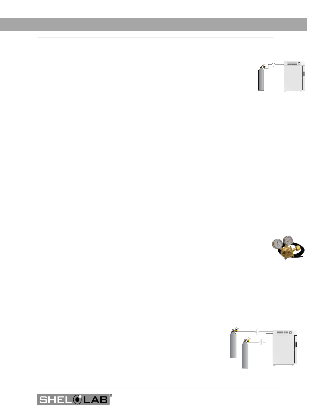
CO2Gas Supply ......................................................................................................................................................................9
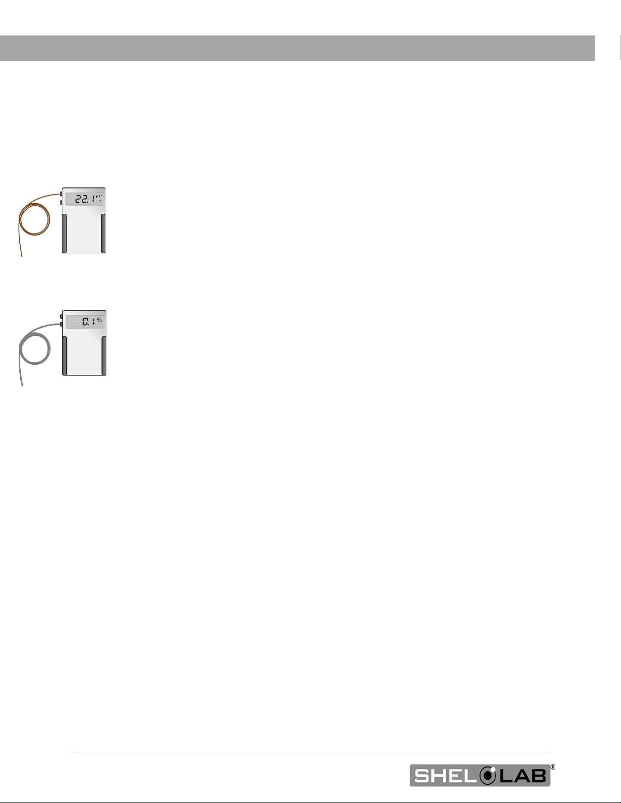
Reference Sensor Devices ................................................................................................................................................ 10
RECEIVING YOUR UNIT ...........................................................................................................................................11
Inspect the Shipment............................................................................................................................................................ 11
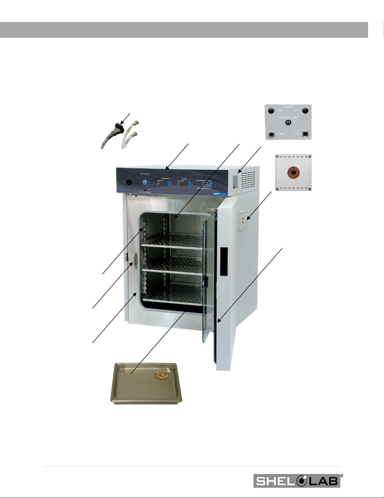
Orientation Image ................................................................................................................................................................ 12
Recording Data Plate Information................................................................................................................................... 13
INSTALLATION .........................................................................................................................................................15
Installation Checklist ........................................................................................................................................................... 15
Required Ambient Conditions........................................................................................................................................... 16
Required Clearances........................................................................................................................................................... 16
Environmental Disruption Sources .................................................................................................................................. 16
Power Source Requirements .............................................................................................................................................17
Lifting and Handling ............................................................................................................................................................ 18
Leveling................................................................................................................................................................................... 18
Install Incubator in Location .............................................................................................................................................. 18
Deionized and Distilled Water.......................................................................................................................................... 18
Installation - Clean and Disinfect..................................................................................................................................... 19
Shelving Installation............................................................................................................................................................. 19
Access Port Stopper ............................................................................................................................................................ 21
GRAPHIC SYMBOLS ............................................................................................................................................... 23
CONTROL PANEL OVERVIEW .............................................................................................................................. 25
OPERATION.............................................................................................................................................................. 27
Theory of Operation ............................................................................................................................................................27
Put the Incubator into Operation .................................................................................................................................... 29
Humidifying the Incubator.................................................................................................................................................. 31
Set the Temperature Setpoint ......................................................................................................................................... 32
Muting the Audible Temperature Alarm....................................................................................................................... 33
Automatic Door Cutoff ....................................................................................................................................................... 33
Start a Flow of CO2............................................................................................................................................................. 34
Set the CO2Setpoint .......................................................................................................................................................... 35
Muting the Audible CO2Alarm ........................................................................................................................................ 36
No Gas Supply Alarm (ngs)............................................................................................................................................... 36
Set the Over Temperature Limit.......................................................................................................................................37
Decontamination Cycle ..................................................................................................................................................... 38
Aborting the Decontamination Auto Cycle ................................................................................................................... 41
Load the Incubator.............................................................................................................................................................. 42
Accessory Compatibility.................................................................................................................................................... 42
Data Output Capabilities .................................................................................................................................................. 42
Condensation and the Dew Point .................................................................................................................................. 44
USER MAINTENANCE............................................................................................................................................. 45
Cleaning and Disinfecting................................................................................................................................................. 45
Minimizing Contamination Exposure ............................................................................................................................. 46
Gas Lines and HEPA Filters...............................................................................................................................................47
Storage of the Incubator ....................................................................................................................................................47
Maintaining Atmospheric Integrity ..................................................................................................................................47
Electrical Components........................................................................................................................................................47
Calibrate the Temperature display................................................................................................................................ 48

5 | Page
Calibrate the CO2 Display ................................................................................................................................................. 52
UNIT SPECIFICATIONS .......................................................................................................................................... 57
Weight......................................................................................................................................................................................57
Dimensions.............................................................................................................................................................................57
Capacity ..................................................................................................................................................................................57
Chamber CO2Performance ............................................................................................................................................. 58
Chamber Temperature ...................................................................................................................................................... 58
Power...................................................................................................................................................................................... 58
PARTS AND CONSUMABLES................................................................................................................................ 59
Components.......................................................................................................................................................................... 59
Ordering ................................................................................................................................................................................. 60
Accessories...........................................................................................................................................................................60

6 | Page
TABLE OF CONTENTS

7 | Page
INTRODUCTION
Thank you for purchasing a SHEL LAB product. We know you have many choices in today’s competitive
marketplace when it comes to constant temperature equipment. We appreciate you choosing ours. We
stand behind our products and will be here for you if you need us.
READ THIS MANUAL
Failure to follow the guidelines and instructions in this user manual may create a protection
impairment by disabling or interfering with the unit safety features. This can result in injury or death.
Before using the unit, read the manual in its entirety to understand how to install, operate, and
maintain the unit in a safe manner. Keep this manual available for use by all operators. Ensure all
operators are given appropriate training before the unit begins service.
SAFETY CONSIDERATIONS AND REQUIREMENTS
Follow basic safety precautions, including all national laws, regulations, and local ordinances in your
area regarding the use of this unit. If you have any questions about local requirements, please
contact the appropriate agencies.
SOPs
Because of the range of potential applications, this unit can be used for, the operator or their
supervisors must draw up a site-specific standard operating procedure (SOP) covering each
application and associated safety guidelines. This SOP must be written and available to all operators
in a language they understand.
Intended Applications and Locations
The incubators are intended for constant temperature, CO2-enriched, non-humidified general
incubation applications in professional, industrial, and educational environments. The units are not
intended for use at hazardous or household locations.
Power
Your unit and its recommended accessories are designed and tested to meet strict safety
requirements.
•The unit is designed to connect to a power source using the specific power cord type
shipped with the unit.
•Always plug the unit power cord into a protective earth grounded electrical outlet
conforming to national and local electrical codes. If the unit is not grounded properly, parts
such as knobs and controls can conduct electricity and cause serious injury.
•Do not bend the power cord excessively, step on it, or place heavy objects on it.
•A damaged cord can be a shock or fire hazard. Never use a power cord if it is damaged or
altered in any way.
•Use only approved accessories. Do not modify system components. Any alterations or
modifications to your unit can be dangerous and void your warranty.

8 | Page
INTRODUCTION
CONTACTING ASSISTANCE
Phone hours for Sheldon Technical Support are 6 am – 4:30 pm Pacific Coast Time (west coast of
the United States, UTC -8), Monday – Friday. Please have the following information ready when
calling or emailing Technical Support: the model number, serial number, and part number, (see
page 13).
support@sheldonmfg.com
1-800-322-4897 extension 4
(503) 640-3000 extension 4
FAX: (503) 640-1366
Sheldon Manufacturing, INC.
P.O. Box 627
Cornelius, OR 97113
USA
MANUFACTURING WARRANTY
For information on your warranty and online warranty registration please visit:
•sheldonmanufacturing.com/warranty
ENGINEERING IMPROVEMENTS
Sheldon Manufacturing continually improves all of its products. As a result, engineering changes and
improvements are made from time to time. Therefore, some changes, modifications, and
improvements may not be covered in this manual. If your unit’s operating characteristics or
appearance differs from those described in this manual, please contact your SHEL LAB dealer or
customer service representative for assistance.

9 | Page
INTRODUCTION
Note: A CO2gas regulator must be purchased separately from the incubator.
CO2GAS SUPPLY
Supply Required!
The incubator must be connected to a carbon dioxide gas supply system in order to establish and
maintain a CO2-enriched incubation chamber atmosphere. The supply can be a building CO2gas system
or a supply cylinder (tank).
Supply Quality
Use medical or food-grade CO2. Use of industrial CO2 risks introducing contaminants into the chamber,
may damage the incubator, and will void the manufacturing defect warranty.
Supply Source and Pressure
The incubator requires 15 – 20 psi of CO2gas pressure at the incubator intake port (labeled CO2 to
Chamber).
Dual Stage Regulator
If connecting to a supply cylinder, use a two-stage CO2pressure regulator. During normal
operations, the incubator uses only small quantities of CO2to maintain the chamber gas
concentration, and precise regulation of the gas input flow is vital for the incubator performance.
Some single-stage regulators have two gauges. Make certain your regulator is a two-stage
regulator. Each cylinder requires a regulator.
Regulator Not Included
See page 59 for ordering information.
Dual Cylinder Connection
The incubator can be connected simultaneously to two CO2supply cylinders.
The unit automatically switches drawing from one cylinder to the other when
the first cylinder runs out of CO2. Two gas regulators are required for this
configuration.

10 | Page
INTRODUCTION
REFERENCE SENSOR DEVICES
Must be purchased separately
Reference sensor devices or a combined device are required for calibrating the
incubator temperature and CO2displays.
Reference devices must meet the following standards:
•Accurate to at least 0.1°C
•Accurate to at least 0.1% CO2
The devices should be regularly calibrated, preferably by a third party.
Temperature Probes
For temperature, use a digital device with wire thermocouple probes that can be
introduced into the incubation chamber through the unit access port. Select
thermocouples suitable for the application temperature you will be calibrating at.
CO2 Sampling
For best CO2accuracy, use a digital gas analyzer with sample tubing connecting to
the incubator CO2sample port. The barbed adapter gas fitting on the sample port
connects to 3/16-inch (4.76mm) inner diameter (ID), 5/16-inch (7.94mm) outside
diameter (OD) tubing.
Why Probes and Tubing?
Reference readings taken outside the chamber using wire temperature probes and
CO2drawn through the sample port avoid chamber door openings. Openings disrupt
the chamber temperature and CO2 concentration level. Each disruption requires a
minimum 1-hour wait to allow the atmosphere to re-stabilize before continuing.
No Alcohol or Mercury Thermometers
Alcohol thermometers do not have sufficient accuracy to conduct accurate
temperature calibrations. Never place a mercury thermometer in the incubation
chamber! Always use thermocouple probes.
CO
2
Reference
Temperature
Reference

11 | Page
RECEIVING YOUR UNIT
INSPECT THE SHIPMENT
•When a unit leaves the factory, safe delivery becomes the responsibility of the carrier.
•Damage sustained during transit is not covered by the manufacturing defect warranty.
•Save the shipping carton until you are certain that the unit and its accessories function
properly.
When you receive your unit, inspect it for concealed loss or damage to its interior and exterior. If you
find any damage to the unit, follow the carrier’s procedure for claiming damage or loss.
1. Carefully inspect the shipping carton for damage.
2. Report any damage to the carrier service that delivered the unit.
3. If the carton is not damaged, open the carton and remove the contents.
4. Inspect the unit for signs of damage. See the orientation depiction on the next page as a
reference.
5. The unit should come with an Installation and Operation Manual.
6. Verify that the correct number of accessory items have been included.
Included Accessories
1 Anti-Microbial
Copper Token
4 Leveling Feet
1 Power Cord
1 Stainless Steel
Humidity Pan
3 Stainless Steel
Shelves
6 Stainless Steel
Shelf Slides
4 Stainless Steel
Shelf Standards
1 CO2Tubing Kit
7. A silicone stopper should come installed in the access port on the right side of the unit.
Verify the presence of the stopper.
8. Carefully check all packaging for accessory items before discarding.

12 | Page
SCO6AD
RECEIVING YOUR UNIT
ORIENTATION IMAGE
Control Panel
Viewing Door Latch
Shelf Standard Mounting
Rail
Incubation Chamber
Outer Chamber Door
Side Access Port
with Copper Filter
(Side of Unit)
Chamber Door Gasket
Viewing Door Gasket
Humidification Pan with Copper Token
Back of Unit
Alarm Dry Contact,
CO2Sample Port,
USB-Style Serial Port
CO
2
In Ports
Fuse in Power Inlet
Viewing Door

13 | Page
RECEIVING YOUR UNIT
RECORDING DATA PLATE INFORMATION
The data plate contains the incubator model number and serial number. Tech Support will need this
information during any support call. Record it below for future reference.
•The data plate is located on the right side of the unit, above the copper-filtered access port
Data Plate Information
Model Number
Serial Number

14 | Page
RECEIVING YOUR UNIT

15 | Page
INSTALLATION
INSTALLATION CHECKLIST
For installing the unit in a workspace.
Pre-Installation
Check that the required ambient conditions and ventilation spacing for
the incubator are met, page 16.
•Unit dimensions may be found on page 52
Check for performance-disrupting heat and cold sources in the
environment, page 16
Check that a suitable electrical outlet and power supply is present,
page 17
Procure a CO2gas supply for the incubator. See page 9.
Install the Incubator in a suitable location
Review the lifting and handling instructions, page 18
Install the incubator in its workspace location, page 18
Make sure the incubator is level, page 18
Set up the Incubator for use
Clean and disinfect the incubator and shelving accessories that will be
placed in the incubation chamber, page 19
Install the shelving in the incubation chamber, page 19
Connect the incubator to the CO2gas supply source, page 20
Verify that the high-temperature silicone stopper is installed in the
access port on the outside of the incubator, page 21

16 | Page
INSTALLATION
REQUIRED AMBIENT CONDITIONS
These units are intended for use indoors, at room temperatures between 15°C and 30°C (59°F and 86°F),
at no greater than 80% Relative Humidity (at 25°C / 77°F). Operating outside these conditions may
adversely affect its incubator temperature stability and effective operating range.
REQUIRED CLEARANCES
These clearances are required to provide air flows sufficient for ventilation and cooling.
4 inches (102mm) of clearance is required on the sides and back.
2 inches (51mm) of headspace clearance between the top of the unit and any overhead partitions.
ENVIRONMENTAL DISRUPTION SOURCES
When selecting a location to install the unit, look for sources of heat, cold, and moving air that can affect
the chamber temperature and atmospheric integrity.
•Ovens, autoclaves, and any device that produces significant radiant heat
•High-traffic areas
•Direct sunlight
•Heating and cooling ducts or other sources of fast-moving air currents
2” (51mm)
2” (51mm)
4” (102mm)
4” (102mm)
4” (102mm)
25.5 inches (648mm)
Door Swing
Access Port
Data and
Sample Ports

17 | Page
INSTALLATION
POWER SOURCE REQUIREMENTS
When selecting a location for the unit, verify each of the following requirements is satisfied.
Power Source
The power source for the unit must match the voltage and match or exceed the ampere
requirements listed on the unit data plate. These units are intended for 110 – 120V 50/60 Hz
applications at 12 amps.
•Supplied voltage must not vary more than 10% from the data plate rating. Damage to the
unit may result if the supplied voltage varies more than 10%.
•The wall power source must be protective earth grounded.
•Use a separate circuit to prevent loss of the unit due to overloading or circuit failure.
•The recommended wall circuit breakers for these units are 15 amps.
•The wall power source must conform to all national and local electrical codes.
Power Cord
The unit must be positioned so that all users can quickly unplug the cord in the event of an
emergency.
•The unit comes provided with a 125 volt, 15Amp, 9ft 5 in (2.86m) NEMA 5-15P power cord.
•Always use this cord or an identical replacement.
Fuses
The unit ships with a fuse installed in the power cord inlet.
•The fuse must be installed and intact for the unit to operate.
•Always find and fix the cause of a blown fuse prior to putting the unit back into operation.
•Fuse type
o250V, Type H 12.5 amp, 5X20mm
Standard 15-
amp NEMA
5-15 power
outlet.

18 | Page
INSTALLATION
LIFTING AND HANDLING
The unit is heavy. Use appropriate lifting devices that are sufficiently rated for these loads. Follow these
guidelines when lifting the unit.
•Lift the unit only from its bottom surface.
•Doors, handles, and knobs are not adequate for lifting or stabilization.
•Restrain the unit completely while lifting or transporting so it cannot tip.
•Remove all moving parts, such as shelves and trays, and lock doors in the closed position
during transfers to prevent shifting and damage.
LEVELING
Install the leveling feet in the 4 corner holes on the bottom of the unit. The unit must be level and
stable for safe operation.
Note: To prevent damage when moving the unit, turn all four leveling feet so that the leg of each
foot sits inside the unit.
INSTALL INCUBATOR IN LOCATION
Install the unit in a workspace location that meets the criteria discussed in the previous entries of the
Installation section.
DEIONIZED AND DISTILLED WATER
Do not use deionized water to clean or humidify the incubator. Use of deionized water may corrode
metal surfaces and voids the warranty. The manufacturer recommends the use of distilled water in
the resistance range of 50K Ohm/cm to 1M Ohm/cm, or a conductivity range of 20.0 uS/cm to 1.0
uS/cm, for cleaning and humidifying applications.

19 | Page
INSTALLATION
INSTALLATION -CLEAN AND DISINFECT
Cleaning and disinfecting the incubation chamber and shelving components now reduces the risk
of contamination. The chamber was cleaned and disinfected at the factory, however, the unit may
have been exposed to contaminants during shipping.
•Remove all protective wrappings from shelving components prior to cleaning.
•See the Cleaning and Disinfecting entry on page 45 for information on how to clean and
disinfect without damaging the incubator or its components.
SHELVING INSTALLATION
Install the shelf standard rails.
a. Align the keyhole slot of the standard with the mounting
peg on the side of the chamber wall.
b. Mount the standard on the peg.
Install the shelf slides.
a. Insert the shelf slide into the shelf standard using a
rocking motion.
•The shelf slide will sit level when correctly installed.
Place the shelves.
a. Slide into position.

20 | Page
INSTALLATION
CONNECT TO THE CO2SUPPLY
Note: See page 9 for CO2supply requirements.
Connect the supply source to the incubator.
Optional: If connecting a second supply cylinder, do so now.
Do not initiate a flow of CO2to the incubator at this time.
Reminder: The building supply system or cylinder regulator(s) must deliver 15 – 20 psi flow pressure to
the incubator.
End of procedure
CO
2
to Chamber
“IN”
Connects to 3/16”
(4.76mm) ID Tubing
Single Source
Dual Source
“IN”
Optional Tubing Kit
with Inline HEPA Filter
Table of contents
Other Shel lab Accessories manuals

Shel lab
Shel lab SCO5A User manual

Shel lab
Shel lab SMI31-2 User manual

Shel lab
Shel lab SMI Series User manual

Shel lab
Shel lab SMI2 User manual

Shel lab
Shel lab SCO6WE-2 User manual

Shel lab
Shel lab SCO6AD-2 User manual

Shel lab
Shel lab SCO5W User manual

Shel lab
Shel lab SCO6WE User manual

Shel lab
Shel lab 5215 User manual
Popular Accessories manuals by other brands

PCB Piezotronics
PCB Piezotronics 378A21 Installation and operating manual

Hytronik
Hytronik HMW32 quick start guide

esera
esera 11160 quick guide

Lightolier
Lightolier ZYLINDER GLAS Instructions for installation

S+S Regeltechnik
S+S Regeltechnik HYGRASGARD AFTM-LQ-CO2-Modbus manual

Omron
Omron ZG - user manual