Shel lab SCO6WE User manual

ECONOMY WATER-JACKETED CO2INCUBATOR
110 – 120 Volts
Installation - Operation Manual
SCO6WE

2 | Page
48TWarning:48T This product contains chemicals, including triglycidyl isocyanurate, known to the State of
California to cause cancer as well as birth defects or other reproductive harm. For more information,
go to 33Twww.P65Warnings.ca.gov33T.
48T¡Advertencia! Este producto contiene sustancias químicas, incluido el triglicidil isocianurato, que el
estado de California sabe que causa cáncer, así como defectos de nacimiento u otros daños
reproductivos. Para obtener más información, visite www.P65Warnings.ca.gov48T.
Avertissement!Ce produit peut vous exposer à des produits chimiques, dont l'isocyanurate de
triglycidyle, reconnu par l'État de Californie pour provoquer le cancer, des anomalies congénitales
ou d'autres problèmes de reproduction. Pour plus d'informations, visitez le site
www.P65Warnings.ca.gov.

3 | Page
SCO ECONOMY WATER-JACKETED CO2INCUBATORS
110 – 120 Voltage
Part Number (Manual): 4861748
Revision: April 14, 2020
SHEL LAB is a brand of Sheldon Manufacturing, INC, an ISO 9001
certified manufacturer.
Safety Certifications
These units are TÜV listed as water jacket incubators for professional, industrial, or educational use
where the preparation or testing of materials is done at an ambient air pressure range of 22.14 – 31.3
inHg (75 – 106 kPa), with no flammable, volatile, or combustible materials being heated.
These units have been tested to the following requirements:
CAN/CSA C22.2 No. 61010-1:2012
CAN/CSA C22.2 No. 61010-2-010:2004 Reaffirmed: 2014-07
UL 61010-1:2012-05
UL 61010A-2-010:2002-03
EN 61010-1:2010
EN 61010-2-010:2014
Supplemented by: UL 61010-2-010:2015

4 | Page
TABLE OF CONTENTS
INTRODUCTION .........................................................................................................................................................7
Read this Manual.................................................................................................................................................................... 7
Safety Considerations and Requirements ...................................................................................................................... 7
Contacting Assistance ..........................................................................................................................................................8
Manufacturing Warranty ......................................................................................................................................................8
Engineering Improvements..................................................................................................................................................8
CO2Gas Supply ......................................................................................................................................................................9
Reference Sensor Devices ................................................................................................................................................ 10
RECEIVING YOUR UNIT ...........................................................................................................................................11
Inspect the Shipment............................................................................................................................................................ 11
Orientation Photo ................................................................................................................................................................. 12
Record Data Plate Information......................................................................................................................................... 13
INSTALLATION .........................................................................................................................................................15
Installation Procedure Checklist ...................................................................................................................................... 15
Required Ambient Conditions........................................................................................................................................... 16
Required Clearances........................................................................................................................................................... 16
Power Source Requirements .............................................................................................................................................17
Lifting and Handling ............................................................................................................................................................ 18
Leveling................................................................................................................................................................................... 18
Install the Incubator ............................................................................................................................................................. 19
Deionized and Distilled Water.......................................................................................................................................... 19
Installation - Clean and Disinfect..................................................................................................................................... 19
Install the Chamber Ceiling Air Duct.............................................................................................................................. 20
Shelving Installation............................................................................................................................................................. 21
Connect to the CO2Supply .............................................................................................................................................. 22
Access Port Stopper ........................................................................................................................................................... 23
Fill the Water Jacket........................................................................................................................................................... 23
GRAPHIC SYMBOLS ............................................................................................................................................... 25
CONTROL PANEL OVERVIEW .............................................................................................................................. 27
OPERATION.............................................................................................................................................................. 29
Theory of Operation ........................................................................................................................................................... 29
Put the Incubator into Operation ..................................................................................................................................... 31
Humidify the Incubator ...................................................................................................................................................... 33
Set the Temperature Setpoint ......................................................................................................................................... 34
Muting the Audible Temperature Alarm....................................................................................................................... 35
Automatic Door Cutoffs ..................................................................................................................................................... 35
Start a Flow of CO2............................................................................................................................................................. 36
Set the CO2Setpoint ...........................................................................................................................................................37
Muting the Audible CO2Alarm ........................................................................................................................................ 38
No Gas Supply Alarm (NGS)............................................................................................................................................. 38
Set the Over Temperature Limit (OTL) .......................................................................................................................... 39
Loading Samples................................................................................................................................................................. 40
Accessory Compatibility.................................................................................................................................................... 40
Data Output Capabilities ................................................................................................................................................... 41
Condensation and the Dew Point .................................................................................................................................. 42
USER MAINTENANCE............................................................................................................................................. 43
Cleaning and Disinfecting................................................................................................................................................. 43
Minimizing Contamination Exposure ............................................................................................................................. 44
Maintaining Atmospheric Integrity ................................................................................................................................. 44
Gas Lines and HEPA Filters.............................................................................................................................................. 45
Electrical Components....................................................................................................................................................... 45
Storing the Incubator.......................................................................................................................................................... 45
Calibrate the Temperature Display................................................................................................................................ 46

5 | Page
Calibrate the CO2 Display ................................................................................................................................................. 50
Anode and Water Quality ................................................................................................................................................. 54
UNIT SPECIFICATIONS .......................................................................................................................................... 55
Weight..................................................................................................................................................................................... 55
Dimensions............................................................................................................................................................................ 55
Max Shelves For Unit ......................................................................................................................................................... 56
Capacity ................................................................................................................................................................................. 56
CO2.......................................................................................................................................................................................... 56
Temperature ......................................................................................................................................................................... 56
Power...................................................................................................................................................................................... 56
PARTS LIST............................................................................................................................................................... 57
Accessories........................................................................................................................................................................... 58
Ordering ................................................................................................................................................................................. 58

6 | Page
TABLE OF CONTENTS

7 | Page
INTRODUCTION
Thank you for purchasing a SHEL LAB incubator. We know you have many choices in today’s competitive
marketplace when it comes to constant temperature equipment. We appreciate you choosing ours. We
stand behind our products and will be here if you need us.
READ THIS MANUAL
Failure to follow the guidelines and instructions in this user manual may create a protection
impairment by disabling or interfering with the unit safety features. This can result in injury or death.
Before using the unit, read the manual in its entirety to understand how to install, operate, and
maintain the unit in a safe manner. Ensure all end-users are given appropriate training before the unit
begins service.
Keep this manual available for use by all end-users.
SAFETY CONSIDERATIONS AND REQUIREMENTS
Follow basic safety precautions, including all national laws, regulations, and local ordinances in your
area regarding the use of this unit. If you have any questions about local requirements, please
contact the appropriate agencies.
SOPs
Because of the range of potential applications this unit can be used for, the end-user or their
supervisors must draw up a site-specific standard operating procedure (SOP) covering each
application and associated safety guidelines. This SOP must be written and available to all end-users
in a language they understand.
Intended Applications and Locations
This incubator is intended for constant temperature, humidified microbiological incubation
applications in professional, industrial, and educational environments. The unit is not intended for
use at hazardous or household locations.
Power
Your unit and its recommended accessories are designed and tested to meet strict safety
requirements.
•The unit is designed to connect to a power source using the specific power cord type
shipped with the unit.
•Always plug the unit power cord into a protective earth grounded electrical outlet
conforming to national and local electrical codes. If the unit is not grounded properly, parts
such as knobs and controls can conduct electricity and cause serious injury.
•Do not bend the power cord excessively, step on it, or place heavy objects on it.
•A damaged cord can be a shock or fire hazard. Never use a power cord if it is damaged or
altered in any way.
•Use only approved accessories. Do not modify system components. Any alterations or
modifications to your unit not explicitly authorized by the manufacturer can be dangerous
and are not covered by the manufacturing defect warranty.

8 | Page
INTRODUCTION
CONTACTING ASSISTANCE
Phone hours for Sheldon Customer Support are 6 am – 4:30 pm Pacific Coast Time (west coast of
the United States, UTC -8), Monday – Friday. Please have the following information ready when
calling or emailing Customer Support: the model number, serial number, and part number (see
page 13).
support@sheldonmfg.com
1-800-322-4897 extension 4
(503) 640-3000 extension 4
FAX: (503) 640-1366
Sheldon Manufacturing, INC.
P.O. Box 627
Cornelius, OR 97113
USA
MANUFACTURING WARRANTY
For information on your warranty and online warranty registration please visit:
•sheldonmanufacturing.com/warranty
ENGINEERING IMPROVEMENTS
Sheldon Manufacturing continually improves all of its products. As a result, engineering changes and
improvements are made from time to time. Therefore, some changes, modifications, and
improvements may not be covered in this manual. If your unit’s operating characteristics or
appearance differs from those described in this manual, please contact your SHEL LAB dealer or
customer service representative for assistance.

9 | Page
INTRODUCTION
Note: A CO2gas regulator must be purchased separately from the incubator.
CO2GAS SUPPLY
Supply Required
The incubator must be connected to a carbon dioxide gas supply system in order to
establish and maintain a CO2-enriched incubation chamber atmosphere. The supply
can be a building CO2gas system or a supply cylinder (tank).
Supply Quality
Use medical or food grade CO2. Use of industrial CO2 risks introducing contaminants into the chamber,
may damage the incubator, and is not covered by the manufacturing defect warranty.
Supply Source and Pressure
The incubator requires 15 – 20 psi of CO2gas pressure at the incubator intake port (labeled CO2 to
Chamber).
Dual-Stage Regulator
If connecting to a supply cylinder, always use a dual-stage CO2pressure regulator. During normal
operations, the incubator uses small quantities of CO2to maintain the chamber gas concentration.
Under these conditions, precise regulation of the gas input flow is vital for the incubator
performance. Some single-stage regulators have two gauges. Make certain your regulator is a
dual-stage regulator.
Regulator Not Included
See page 58 for ordering information.
10 | Page
INTRODUCTION
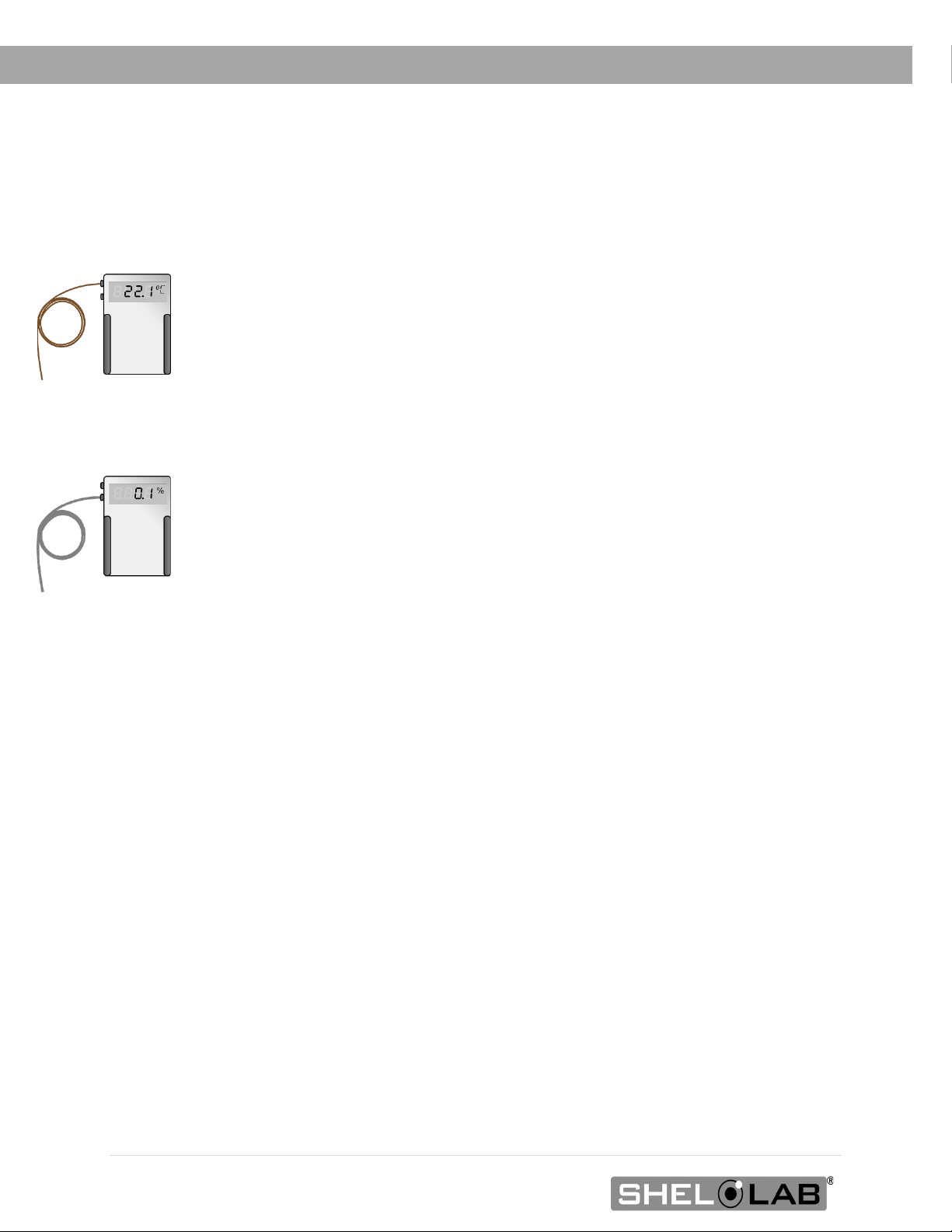
REFERENCE SENSOR DEVICES
Must be purchased separately
Reference sensor devices or a combined device are required for calibrating the
incubator temperature and CO2displays.
Reference devices must meet the following standards:
•Accurate to at least 0.1°C
•Accurate to at least 0.1% CO2
The devices should be regularly calibrated, preferably by a third party.
Temperature Probes
For temperature, use a digital device with a wire thermocouple probe that can be
introduced into the incubation chamber through the unit access port. Select a
thermocouple suitable for the application temperature you will be calibrating at.
CO2 Sampling
For best CO2accuracy, use a digital gas analyzer with sample tubing connecting to
the incubator CO2sample port. The barbed adapter gas fitting on the port connects
to 3/16-inch (4.76 mm) inner diameter (ID), 5/16-inch (7.94 mm) outside diameter
(OD) tubing.
Why Probes and Tubing?
Reference readings taken outside the chamber using wire temperature probes and
CO2sample tubing drawn through the sample port avoid chamber door openings.
Openings disrupt the chamber temperature and CO2 concentration level. Each
disruption requires a minimum 1-hour wait to allow the atmosphere to re-stabilize
before continuing.
No Alcohol or Mercury Thermometers
Alcohol thermometers do not have sufficient accuracy to conduct accurate
temperature calibrations. Never place a mercury thermometer in the incubation
chamber. Always use thermocouple probes.
CO
2
Reference
Temperature
Reference
11 | Page
RECEIVING YOUR UNIT
INSPECT THE SHIPMENT
•When a unit leaves the factory, safe delivery becomes the responsibility of the carrier.
•Damage sustained during transit is not covered by the manufacturing defect warranty.
•Save the shipping carton until you are certain that the unit and its accessories function
properly.
When you receive your unit, inspect it for concealed loss or damage to its interior and exterior. If you
find any damage to the unit, follow the carrier’s procedure for claiming damage or loss.
1. Carefully inspect the shipping carton for damage.
2. Report any damage to the carrier service that delivered the unit.
3. If the carton is not damaged, open the carton and remove the contents.
4. Inspect the unit for signs of damage. See the orientation depiction on the next page as a
reference.
5. The unit should come with an Installation and Operation Manual.
6. Verify that the correct number of accessory items has been included.
7. Carefully check all packaging for accessory items before discarding.
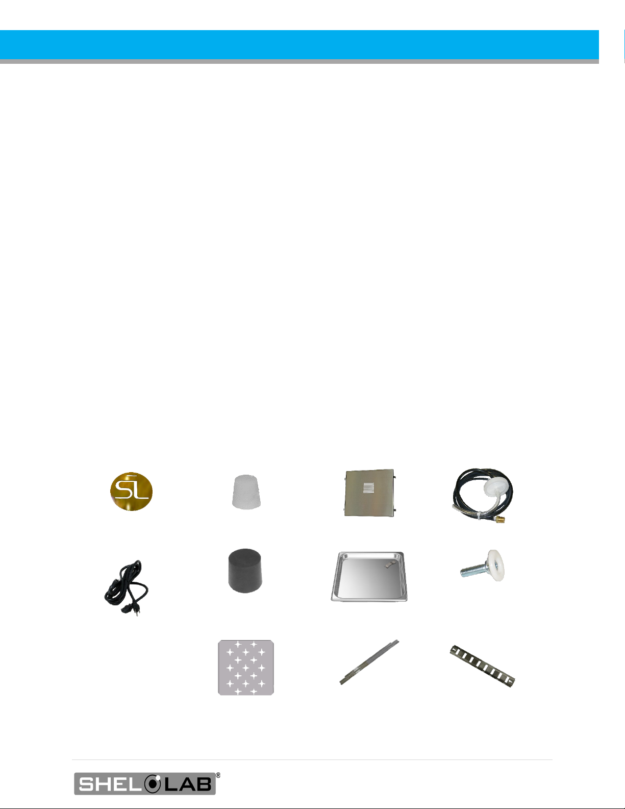
Included Accessories
1 Copper Pan Token
1 Access Port Stopper* 1 Ceiling Air Duct
1 CO2Tubing Kit
1 Power Cord
1 Fill Port Stopper*
1 Humidification Pan
4 Leveling Feet
3 Shelves
6 Shelf Slides
4 Shelf Standards
*The access and water fill stoppers ship installed in their respective ports on the unit.
12 | Page
RECEIVING
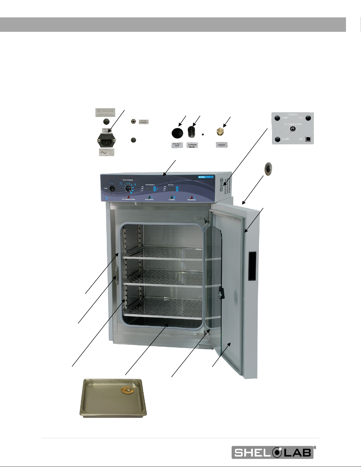
ORIENTATION PHOTO
SCO6WE
Chamber
Gasket
Door Latch
Viewing Door (Glass)
Chamber Door
Chamber Door
Handle
Access Port
Door Gasket
Control Panel
Back of Unit
Fuse in Cord Inlet
Back of Unit
Fill Port
Water Jacket Ports
Siphon Port
Anode Top
Shelf Standard Rail
Humidification Pan
Side of Unit
CO
2
Sample Port and USB Port
Side of Unit
CO
2
Gas In Port

13 | Page
RECEIVING
RECORD DATA PLATE INFORMATION
The data plate contains the unit model number, serial number, and part number. Customer Support
will need this information during any support call. Record it below for future reference.
•The data plate is located on the inside of the incubation chamber door in the top right corner.
Data Plate Information
MODEL NO:
SERIAL NO:
PART NO:

14 | Page
RECEIVING

15 | Page
INSTALLATION
INSTALLATION PROCEDURE CHECKLIST
For installing the unit in a new workspace location.
Pre-Installation
Verify a CO2gas supply source suitable for your application is
available and can be connected to the incubator, page 9.
Check that the required ambient conditions for the unit are met,
page 16.
Check that the spacing clearance requirements are met, page 16.
•Unit dimensions may be found on page 55.
Check that a suitable electrical outlet and power supply is present,
page 17.
Install the incubator in a suitable location
Review the lifting and handling instructions, page 18.
Install the unit leveling feet, page 18.
Install the incubator in its workspace location, page 19.
Set up the incubator for use
Clean and disinfect the unit and accessories, page 19.
Install the ceiling air duct in the incubation chamber, page 20.
Install the shelving, page 21.
Connect the incubator to the CO2gas supply source, page 22.
Verify that the silicone stopper is installed in the access port
inside the incubation chamber, page 23.
Fill the water jacket with 19 gallons (72 liters) of water, page 23.
16 | Page
INSTALLATION
REQUIRED AMBIENT CONDITIONS
These units are built for use indoors at room temperatures between 15°C and 30°C (59°F and 86°F), at
no greater than 80% Relative Humidity (at 25°C / 77°F The ambient temperature should not change by
2°C (3.6°F) or more during operation.
Operating outside these conditions may affect the incubator temperature performance.
When selecting a location to install the unit, consider all environmental conditions that can adversely
impact its temperature performance. These include:
•Proximity to ovens, autoclaves, and any device that produces significant radiant heat
•Heating and cooling vents or other sources of fast-moving air currents
•High-traffic areas
•Direct sunlight
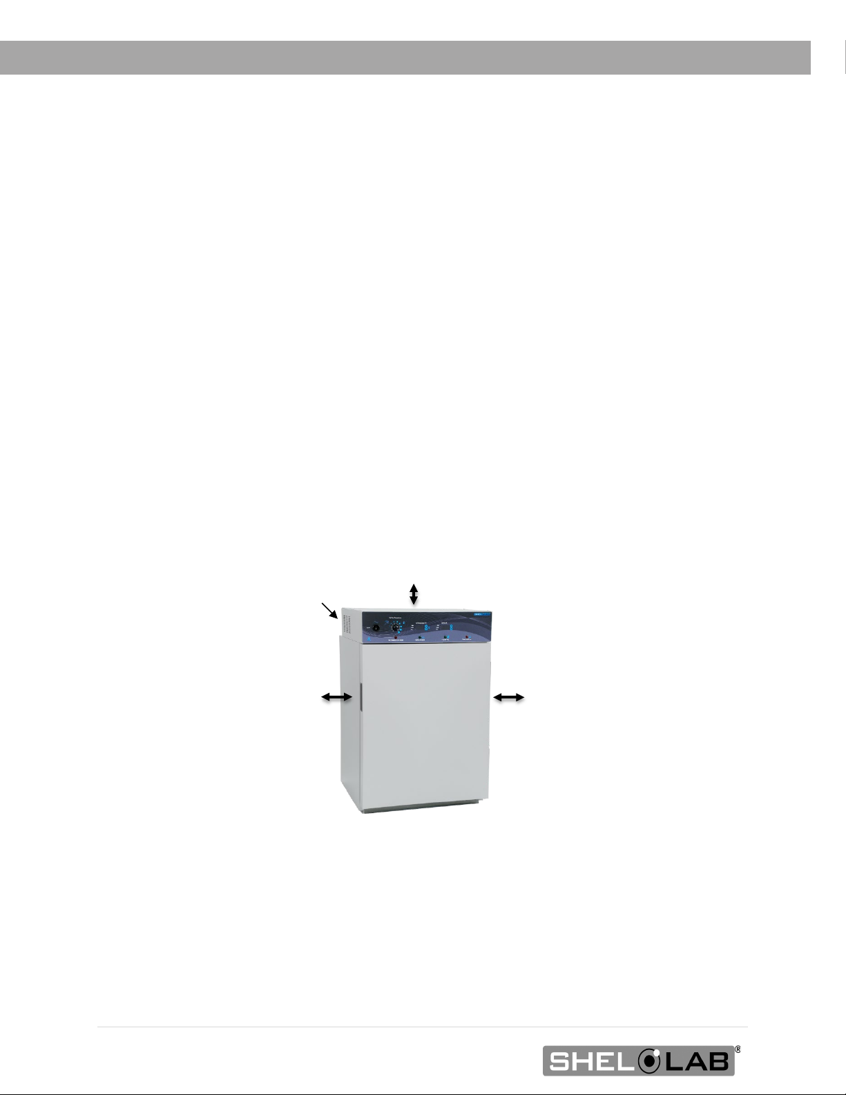
REQUIRED CLEARANCES
These clearances are required to provide air flows for ventilation and cooling.
4 inches (102 mm) of clearance is required on the sides and back.
2 inches (51 mm) of headspace clearance is required between the top of the unit and any overhead
partitions.
Power Cord
2” (51 mm)
4” (102 mm)
4” (102 mm)

17 | Page
INSTALLATION
POWER SOURCE REQUIREMENTS
When selecting a location for the unit, verify each of the following requirements is satisfied.
Power Source: The power source must match the voltage and amperage requirements listed on the
unit data plate. This unit is intended for 110 – 120 volt, 50/60 Hz applications at 6.0 amps.
•The wall power source must be protective earth grounded.
•The unit may be damaged if the supplied voltage varies by more than 10% from the data
plate rating.
•Use a separate circuit to prevent loss of the unit due to overloading or circuit failure.
•The recommended wall circuit breaker for this unit is 15 amps.
•The wall power source must conform to all national and local electrical codes.
Power Cord: The unit must be positioned so that all end-users can quickly unplug the cord in the
event of an emergency.
•The unit is provided with a 125-volt, 15 amp, 9ft 5 in (2.86m) NEMA 5-15P power cord.
Always use this cord or an identical replacement.
Fuse: The unit ships with a fuse installed in the power cord inlet.
•The fuse must be installed and intact for the unit to operate.
•Always find and fix the cause of a blown fuse prior to putting the unit back into operation.
•Fuse type:
o250V T10 Amp, 5x20mm
Standard
NEMA 5-15R
wall socket

18 | Page
INSTALLATION
LIFTING AND HANDLING
The unit is heavy. Use appropriate lifting devices that are sufficiently rated for these loads. Follow these
guidelines when lifting the unit.
•Lift the unit only from its bottom surface.
•Doors, handles, and knobs are not adequate for lifting or stabilization.
•Restrain the unit completely while lifting or transporting so it cannot tip.
•Remove all moving parts, such as shelves and trays, and lock doors in the closed position
during transfers to prevent shifting and damage.
LEVELING
Install the leveling feet in the 4 corner holes on the bottom of the unit. The unit must be level and
stable for safe operation.
Note: To prevent damage when moving the unit, turn all 4 leveling feet so that the leg of each foot
sits inside the unit.

19 | Page
INSTALLATION
INSTALL THE INCUBATOR
Install the unit in a workspace location that meets the criteria discussed in the previous entries of the
Installation section.
DEIONIZED AND DISTILLED WATER
Do not use deionized water to clean the unit, even if DI water is readily available in your laboratory.
•Use of deionized water may corrode metal surfaces and is not covered by the
manufacturing defect warranty.
•The manufacturer recommends the use of distilled water in the resistance range of 50K
Ohm/cm to 1M Ohm/cm, or a conductivity range of 20.0 uS/cm to 1.0 uS/cm, for cleaning
applications.
INSTALLATION -CLEAN AND DISINFECT
The manufacturer recommends cleaning the shelving, ceiling air duct, and chamber prior to
installation of the shelving and ceiling duct in the chamber.
•The unit was cleaned at the factory but may have been exposed to contaminants during
shipping.
•Remove all wrappings and coverings from shelving and the ceiling air duct prior to cleaning
and installation. Do not clean the shelving with deionized water.
•Please see the Cleaning and Disinfecting procedure on page 43 in the User Maintenance
chapter for information on how to clean and disinfect without damaging the unit.

20 | Page
INSTALLATION
INSTALL THE CHAMBER CEILING AIR DUCT
Note: Exercise caution to avoid striking the sensors and blower fan wheel on the chamber ceiling when
installing the duct.
Note: The incubator must be turned off and unplugged when carrying out this procedure.
Install the ceiling air duct to ensure the even flow of air throughout
the incubation chamber space. The incubator will not meet its
temperature uniformity specification without the air duct.
Perform the following steps to install the ceiling air duct.
Place the duct in the chamber.
•The back of the duct should be placed toward the rear of the
chamber.
•The mounting legs on the sides of the duct should be next to
the left and right chamber walls and point down toward the
chamber floor.
Move the air duct up to the top of the chamber.
Carefully seat the duct mounting legs in the shelf-
standard clips.
Back
Step 2
Front
Step 1
Step 3
Chamber Ceiling Air Duct
Back
Front
Table of contents
Other Shel lab Accessories manuals

Shel lab
Shel lab SCO5A User manual

Shel lab
Shel lab SCO5W User manual

Shel lab
Shel lab SCO6AD-2 User manual

Shel lab
Shel lab SCO6WE-2 User manual

Shel lab
Shel lab 5215 User manual

Shel lab
Shel lab SMI31-2 User manual

Shel lab
Shel lab SMI2 User manual

Shel lab
Shel lab SMI Series User manual

Shel lab
Shel lab SCO6AD User manual


