Shenzhen Guanhong Automation SZGH-CNC990TDb series User manual

-Shenzhen Guanhong Automation Co.,Ltd.- SZGH-CNC990TDb(c) Series
CONTENTS
Chapter 1 Preface................................................................................................................................................... 1
Chapter 2 System technical features.....................................................................................................................2
2.1 System constructions.......................................................................................................................................... 2
2.2 System technical parameter................................................................................................................................... 2
2.3 System function..................................................................................................................................................... 2
2.4 System operation condition................................................................................................................................... 3
Chapter 3 Operation explanation......................................................................................................................... 4
3.1 Panel layout and switch(Two types).......................................................................................................... 4
3.2 Keyboard description.............................................................................................................................................4
3.3 Manual Operation.................................................................................................................................................. 6
3.4 Auto operation......................................................................................................................................................12
3.5 Operate safety, prompt alarm...............................................................................................................................16
3.6 Parameters............................................................................................................................................................17
3.6.1 User parameter..................................................................................................................................................17
3.6.2 Speed parameter................................................................................................................................................19
3.6.3 Axis parameter.................................................................................................................................................. 24
3.6.4 Tool parameter.................................................................................................................................................. 30
3.6.5 Other parameter................................................................................................................................................ 30
3.6.6 Work coordinate parameter...............................................................................................................................36
3.6.7 Password........................................................................................................................................................... 38
3.7 Set parameter of tool redeem...............................................................................................................................38
3.8 Screw compensation............................................................................................................................................ 41
3.9 Input/output diagnosis......................................................................................................................................... 44
3.10 Operation of program........................................................................................................................................ 46
Chapter4 Programming....................................................................................................................................... 51
4.1 basic concepts...................................................................................................................................................... 51
4.2 Program instruction............................................................................................................................................. 52
4.3 Preparation functions...........................................................................................................................................55
(1) Rapid motion(G00).............................................................................................................................................. 55
(2) Line interpolation(G01)....................................................................................................................................... 56
(3) Arc interpolation(G02/G03).................................................................................................................................56
(4) Screw thread (G32).............................................................................................................................................. 57
(5) Circularity screw thread(G332/G333)................................................................................................................. 59
(6) Check skip(G31/G311)........................................................................................................................................ 59
(7) Finish machining loop (G70)...............................................................................................................................60
(8) Column thick loop (G71).....................................................................................................................................62
(9) End face thick loop(G72).....................................................................................................................................63
(10) Close cutting loop(G73).....................................................................................................................................64
(11) End face deep hole loop(G74)........................................................................................................................... 64
(12) Slot cutting loop(G75)....................................................................................................................................... 65
(13) Complex screw thread loop(G76)......................................................................................................................66
(14) Column or taper loop(G90)................................................................................................................................68

-Shenzhen Guanhong Automation Co.,Ltd.- SZGH-CNC990TDb(c) Series
(15) Screw thread loop (G92)....................................................................................................................................70
(16) Fixed cycle of tapping (G93)............................................................................................................................. 74
(17) End face loop(G94)............................................................................................................................................75
(18) Fix loop (G22,G800)..........................................................................................................................................77
(19) Back start point(G26,G261,G262,G263,G264).................................................................................................77
(20) Back to G25 point(G25,G61,G611/G612/G613/G614).....................................................................................77
(21) Return Reference (G28/G281/G282/G283/G284/G285/M800/ M881)............................................................78
(22) Setup workpiece coordinate system (G50)........................................................................................................79
(23) Part coordinate setup(G52),Setup tool coor(G184/G185).................................................................................79
(24) Constant speed cutting(G96/G97)..................................................................................................................... 80
(25) Feed mode(G98,G99).........................................................................................................................................81
(26) Pole coordinate program(G15/G16).................................................................................................................. 81
(27) Switch millimeter and inch(G20/G21).............................................................................................................. 82
(28) delay Instruction(G04)....................................................................................................................................... 82
(29) continue feed cutting(G60/G64)........................................................................................................................ 83
(30) Tool radius compensate(G40/G41/G42)............................................................................................................83
(31) Work coordinate(G53/G54/G55/G56/G57/G58/G59).......................................................................................85
(32) Radius compensation of tool C..........................................................................................................................85
(33) Automatical beveling (I) and smoothing(R)......................................................................................................89
G01(G00) Z R automatical smoothing, the coordinate in the next program segment must be G01(G00) Y........... 90
(34) Call sub-program (M97/M98/M99)...................................................................................................................90
(35) Conditional wait, jump instruction.................................................................................................................... 92
(36) T tool.................................................................................................................................................................. 92
(37) S , SS SP speed................................................................................................................................................92
(38) F feed speed........................................................................................................................................................93
(39) Macro program instruction(G65、G66、G67)........................................................................................... 93
(40) User-defined macro instruction(G120-G160,M880-M889)..............................................................................96
4.4 Synthetic instance for programming................................................................................................................... 97
4.5 Usage for grinder................................................................................................................................................. 99
Chapter 5 System installation and connection.................................................................................................100
5.1 System installation and connection................................................................................................................... 100
5.2 System installation dimension...........................................................................................................................100
5.3 System rear view................................................................................................................................................101
5.4 Interface Connection Graph...............................................................................................................................102
5.5 Installation Principle of Lathe........................................................................................................................ 114
5.6 Electrical appliance plate of lathe......................................................................................................................122
Chapter 6 System’s daily maintenance and repair..........................................................................................123
6.1 System’s maintain..............................................................................................................................................123
6.2 Ordinary trouble.................................................................................................................................................123


-Shenzhen Guanhong Automation Co.,Ltd.- SZGH-CNC990TDb(c) Series
1
Chapter 1 Preface
This CNC control system is one middle class flush type CNC control system, aiming
specially at lathe and grinding machine.
Based on modern computer technology, system move control core & PLC program running
technology, and stable unique real time control engine subsystem PTAI, this system ensures the
stabilization of operation. The use of high performance, low power consumption industrial grade
ARM microprocessor as core of hardware, large scale FPGA integrate circuit, multiple layer (4,6)
printed circuit, 32MB flash memory, 8 inch real color LCD which provides friendly man-machine
dialogue interface makes this system work to its best.
Attention for “Attention”:
1.“Attention”reminds operator must be Attention in the relative operation ,otherwise the
operation will fail or some action can not be effected.
2.“Special Attention”reminds operator must be Special Attention in the relative operation,
otherwise it may break down the machine or give rise to accident.
Special hint:
This system has function to backup parameters. After debugging machine, it can backup all
parameters of machine & system and PLC documents to computer. It is convenient not only for
mass debugging, but also for machine recovery to normal after changing system.
Attention :
When use this system for the first time, please read carefully all the
details of each chapter so as to make it work more efficiently.
The functions which are related with 3rd ,4th,5th axis of system
only exist in the controller that user order this functions.
3. The “Run” button on the panel of system can be used when debugging (No.9 parameter
in other parameter to set “Effective” “Invalid”), must plus an external “Run” button when fitting
system, otherwise may cause accident because of the life of button!!!So the system prohibits using
the button for many times, otherwise the consequences has nothing to do with my company.
4.Must be de-energized when connect/plug with ports.

-Shenzhen Guanhong Automation Co.,Ltd.- SZGH-CNC990TDb(c) Series
2
Chapter 2 System technical features
2.1 System constructions
32 bits high performance,high speed, low power consumption industrial grade ARM
microprocessor.
64MB memory.
32Mb user store room.
640x480 8 inch real color LCD Displayer.
Touch screen main and sub panel.
High anti-jamming switch power.
USB movable U disc copy interface.
RS232 interface.
Spindle servo speed control/spindle frequency convention speed control.
Manual pulse generator.
2.2 System technical parameter
controllable axes:X、Z、C/Y、A four axes.
linkage axes:Arc 2-3 axes, liner 2-4 axes.
pulse equivalent:X、Z、C/Y、A axes:0.001mm.
max speed:X、Z、C/Y、A:60000mm/min.
cutting speed:1-10000mm/min.
min input unit:0.001mm.
program size range:± 99999.999.
99 tools management.
controllable liner vertical type or revolving disc type tool changer.
program code:ISO-840 international standard.
program coordinate system definition:ISO-841.
chassis protection complies with regulation of IP43.
2.3 System function
2.3.1 Auto-diagnosis function
All around diagnosis of CPU, storer, LCD, I/O interface, parameter status, coordinates,
machining program etc. shall execute when the system starts or resets. In operation, it makes real
time diagnosis of power, spindle, limit and all I/O interface.
2.3.2 Compensation function
automatic backlash compensation.
tool radius automatic compensation.
tool radius automatic offset and sharp angle transition.
leading screw pitch error automatic compensation.
2.3.3 Abundant instruction system
scaling up/down instruction.
mirror machining instruction.
Multiple tool offset instruction.

-Shenzhen Guanhong Automation Co.,Ltd.- SZGH-CNC990TDb(c) Series
3
program cycle, jump, call and different program ending.
multiple positioning instruction:starting point,setting fixed point,etc.
Linear, circular,spiral line interpolation instruction.
program management instructions: program cycle, call, transfer and different program ending
method, etc.
6 workpiece coordinates system .
2.3.4 Chinese/English menu, full screen edition
Easy operation, convenient viewing.
2.3.5 Abundant debugging functions
it can point out clearly what errors of operation are and guide to correct them.
2.3.6 Program changing between CNC system and IBM/PC series compatible computer
it can conduct CAD/CAM/CAPP auxiliary programming by using Pc series compatible
computer's abundant software resources ,then transfer the CNC program into the system to
machining through(USB movable U disc copy port、RS232 port).Likewise it also can transfer
the program from system to PC through communication port.
2.4 System operation condition
2.4.1 Power supplying
AC 220V(+10%/-15%), Frequency 50Hz±2%. power:≤ 200W.
Attention:it must use isolation transformer to supply power,first input:380V
2.4.2 Climate condition
Operation condition:temperature 0~45℃,relative moisture 40-80%.
storage & transportation condition:temperature -40~55℃,relative moisture <93%(40℃).
atmosphere pressure:86-106kpa.
2.4.3 operation environment:
No excessive flour dust, no acid, no alkali gas and explosive gas, no strong electromagnetic
interference.

-Shenzhen Guanhong Automation Co.,Ltd.- SZGH-CNC990TDb(c) Series
4
Chapter 3 Operation explanation
When using the CNC system, just master the parameter of system, edit program, manual
operation, auto operation. Then you can operate the system easily. There are some details to
instruct hereinafter.
3.1 Panel layout and switch(Two types)
3.2 Keyboard description
3.2.1 Rate increase or decrease
(1) Rapid override(G)
There are six gears in rapid override form 5% to 100%, by adjusting the key of rapid override is
for the following instruction: G00,G26,G28,G611,G613, rapid feed fixed cycle, rapid manual feed.
(2) Feed override(F)

-Shenzhen Guanhong Automation Co.,Ltd.- SZGH-CNC990TDb(c) Series
5
There are sixteen gears in feed override from 0% to 150%, by adjusting the key of feed override
is for the following instruction:G01,G02,G03, the feed override of the fixed cycle and manual run
effectively.
(3) Spindle override(S)
There are sixteen gears in spindle override from 5% to 150%, by adjusting the key of spindle
override is for the speed of the first spindle.
3.2.2 Usage for intervention switch
switch introduction:
Switch
Functions
Emergency stop Driver and motor stop immediately, turns off the
spindle, coolant, waits for the rise of button, and initializes values
(1) The left: normal processing.
(2) The middle: manual to stop feeding, suspend the automatical
feeding. Return to the left to the normal status.
(3) The right: suspend automatic feeding. Return to the left to
the normal status. Spindle is out of control when running with
non-coordinate axis.
Buttons introduction:
Keyboards
Functions
Letter key
Number key
ABCSEFGHIJKLMNOPQRSTUVWXYZ123456789.- :for
program instructions, parameters’ edition; number keys are used for
inputting data and selecting sub-menu.
Edit key
“↑、↓、→、←、Del、PgUp、PgDn”for programming, direction keys can
be used for selecting menu.
Function key
“Esc” returning to upper level or stop a operation
“Enter” selecting sub-menu and changing a newline
“Del” delete program
“program”entering program edition
“parameter” entering parameter setting
“diagnosis” entering diagnosis I/o function
“manual” entering manual status
“handwheel” for starting or stopping handwheel function
“Tool” for confirming current tool ‘s position in machine
tool coordinates system.
“Redeem” for amending tool change errors
“Auto” entering automatic status
“MDI ” entering MDI function
“ ”selecting auto-coordinates/diagram machining
“ ”for single segment or constant work
“ ” for coordinates mode or diagram mode speedy simulating
“ ”for manual increment or constant work

-Shenzhen Guanhong Automation Co.,Ltd.- SZGH-CNC990TDb(c) Series
6
Control key
“ ”spindle cw, ccw rotation
“ ” coolant on/off
“ ”for the shift between electric tool carrier and gang tool carrier
“ ” for the shift between hand-driven continuous high speed and low
speed.
“ ” all axes return to datum point
“ ” for spindle chuck on/off
“ ” for thumbstall on/off
“ ”handwheel gear selection
“ ” adjusting spindle speed
“ ”adjusting feed speed
“ ”adjusting G00 speed
Feed key
+Y+A–Y -A
For X、Y、Z、A axes direction feed
3.3 Manual Operation
The system adjusts one-level menu operation, intuitive, convenient, shortcut, prompt
comprehensive information.Powering the system is to enter the main interface:
Press “Program”key enter program management area.it could edit,alter,diagnosis,delete,and
copy etc.
Press “Parameter”key enter parameter management area.it could refer,alter to every

-Shenzhen Guanhong Automation Co.,Ltd.- SZGH-CNC990TDb(c) Series
7
parameters.
In manual condition,the system could process workpiece.
3.3.1 The key of manual operation
(1) “F”: Taking mm/min as the unit to set the manual feed speed, the input range is from 1 to
30000mm/min. And the input method according to data input method in parameter.
(2) “ -Step”: Switching cycle between “manual continuous” and “manual increment”
(3)“S”: Set the speed of the first spindle. The range is from 0 to 99999, the max depends on
the No.36 parameter in speed parameter.
(4)“I”:Modify the increment in manual increment
(5)“ ”:Press once to increase or decrease 10% feed speed when the No.1 axis
parameter is 0, the range is from 0% to 150%,16 gears totally.
(6) “ ”: Press once to increase or decrease G00 or manual rapid override 20%.The
range is from 5% to 100%,16 gears totally.
(7)“ ”: Press once to increase or decrease the spindle override 10% when the
No.2 parameter in axis parameter is 0. The range is form 5% to 150%,16 gears totally.
(8)“ ”: To switch cycle “0.001” “0.01” “0.1”or “0.1” “0.01” “0.001” in the
handwheel function.
(9)“Diagnosis”: Enter the diagnosis of input or output.
(10)“Setup”:To set a value(G54-G59) in workpiece coordinate(G54-G59);Use “MDI” to
set G54-G59 in lathe coordinate(G53).
(11)“Auto”: Select automatic mode.
(12)“Manual”: Select manual mode.
(13)Spindle controlled: ” Controlling spindle on
clockwise, counterclockwise, stop, correspond to instructions M03,M04,M05. When No.56
parameter in the axis parameter is “8”then press “spindle on counterclockwise” means
counterclockwise inching turning.
(14)“Cooling”: Coolant on or off correspond to instructions M08,M09.
(15)“Chuck”: Chuck tightens or loose correspond to instructions M10, M11.
(16)“Manual speed controlled”: Press “1” “2” “3” “4” “5” “6” “7” “8” “9” to set feed
override “F30” “F60” “F120” “F250” “F500” “F1000” “F1500” “F2000” “F2500” “F3000”.
(17) “Tailstock”: Tailstock tighten or loose correspond to instructions M79,M78.
1) manual main axle condition:
Press the principal axis veer,display M03.
Press the principal axis reverse,display M04.

-Shenzhen Guanhong Automation Co.,Ltd.- SZGH-CNC990TDb(c) Series
8
Press the principal axis stop,display M05.At this condition,users can press
the key to turn off or turn on.
Press M03 turn on point for while.
Press the coolant to turn on or turn off.
Press SP chuck to turn on or turn off.
Press in choosing the position cutting tool.
Press thumb stall to turn on or turn off.
2) Adjust the feed speed: The feed speed percentage can be controlled by the wave band
switch or the key ,the percentage increases or decreases 10%.The scope is 0 -150%,16
grades in all.
3) Control the principal axis speed: The main axle speed percentage can be controlled by the
wave band switch or the key ,the percentage increases or decreases 10%.The scope is 0
-150%,16 grades in all.
4) presses "stops": Stops the manual operation.
5) presses "F", there’s a dialog box used to alter the manual feed speed.That is convenient for
cutting by single axis.
6) presses "S",alter the principle axis’s revolving speed.
7) presses "T", choosing the position cutting tool.
(18) “Switch manual continuous or increment”: Press to manual continuous or
increment, it displays I=XXXX.XXX when it is manual increment.
(19) “Back to datum point”: Press and X or Z, the X or Z axis goes back to zero
point automatically; Press “0”X axis firstly and then Z axis; Press “Esc” to cancel the construction.
The speed controlled by P31, P33in Speed parameter, the direction is determined by P28 in Axis
parameter.
(20) “Tool carrier controlled”: Press to change next tool automatically if it is gang tool
carrier; After changing next tool it will be stop if it is electric tool carrier; Which tool has changed
is going to be redeem. Press “T” and number to change tool directly

-Shenzhen Guanhong Automation Co.,Ltd.- SZGH-CNC990TDb(c) Series
9
(21) “Coordinates feed”: Press “↑ ↓ ← →”correspond to feed A axis and Z axis’s positive or
negative direction.
(22) “Switch speed”: Press to switch the speed to system speed which is changed by
No.1 No.2 parameter in speed parameter when it is in coordinate feed, loosen it that will be the
previous speed. If set the speed higher than the speed in parameter, it will be the set speed to feed.
(23) “Switch coordinates’ display”: Press “PgUp” or “PgDn” to switch the display which
correspond to “relative” “absolute” “machine”.
(24) “Partno clear”: Press Del and Enter.
(25) User-defined “K1”: Turn on/off Y24
(26) User-defined “K2”: Turn on/off Y25
(27) User-defined “K3”: Turn on/off Y26
(28) “Incremental coordinate”: Press “Setup” to fix or set 0 after select “relative” coordinate.
Attention: Lath coordinate clear: Press “E” in parameter and then press “Enter”.
3.3.2 Manual continuous
Continuous operation is to press the time as the basis, Press to feed, up to stop feeding. Making
sure the axis and using “↑ ↓ ← →” to feed, the speed of feed is determined by display on the
interface(F) times the rate.
When continuous starting, press “ -Rapid” to switch the speed to P1,P2 in Speed
parameter. If set the speed higher than the speed in parameter, the feed speed will be P1,P2 in
Speed parameter times rapid override.
In order to facilitate the user single axis cutting in the manual function, setting the manual
speed in manual status. Press “F” and input the speed.
When the hard limit point beyond positive and negative feed running axis two direction at, stop
the feed and prompt to feed reverse direction.(the same as hereinafter)
The manual maximum speed is limited by P3 in Speed parameter, when setting the speed is
higher than the value of parameter, then will be P3 in Speed parameter.
When P38=8 in other paramter, “ ” is change into a switch, press once to turn on (no
more to always press), press again to turn off.
3.3.3 Manual increment
This operation is to set the value of increment as the basis, press “↑ ↓ ← →” once to run a
value of increment. It will prompts “I=0010.000” in manual increment represent for the value of
increment is 10mm, press “I” to revise and Enter.
The speed is the speed on display(F) times the rate.
3.3.4 Back to lathe’s datum point (reference point/Home/zero point)
There are two ways to back to datum point in this system, not only the switch for datum point,
but also can set floating point, the methods as follows:
Switch for datum point: Back to datum point operation is to feed every axis to lathe’s datum
point position in turn. When the parameter of feeding axis which back to datum point is 0, the axis

-Shenzhen Guanhong Automation Co.,Ltd.- SZGH-CNC990TDb(c) Series
10
of coordinate detects zero point and return to the pulsing signal of “Zero”, the data of lathe’s
coordinate will be 0 automatically.
Switch on the power supply of the system, release alarm and the button of emergency after the
CNC is power off, the need to back to datum point to set lathe’s coordinate correctly.
Instruction:
1. The system requires for backing to zero point every time when it is power on, the requirement
can be set by P26 in Axis parameter, it can be prompt or force;
2. The way and type of detecting signal can be set by P27 in Axis parameter, so detect the switch of
datum point is effective, also detect the Z pulsing signal of electrical motor after detecting the
switch of datum point (precision higher), detect forward or reverse for Z pulsing signal of electrical
motor.
3. The direction for backing to datum point can be set by P28 in Axis parameter, D2 D4 correspond
to X Z axis, 0 is forward, 1 is reverse.
4. The sequence of X Z back to datum point can be set by P28 in Axis parameter, X is first when
D8 is 0, Z is first when D8 is 1.
5. The type of the switch for datum point can be set by P29 in Axis parameter, D0 D2 correspond to
X Z axis,0 is always on, 1 is always off.
6. The max length of detecting Z pulse of electrical motor can be set by P30,P31 in Axis parameter,
the value must less than the pulse of electrical motor run a cycle.
7. The shifting distance after backing to datum point can be set by P32,P33 in Axis parameter, rapid
move coordinate to the value of parameter after backing to homing. No switch for Home: To set
floating point to make sure, turn on corresponding function of floating point by P23 in Axis
parameter, setting P24,P25 to make sure X axis’ and Z axis’ floating point, zero point of lathe.
The steps to set floating point as follows:
1. Setting the No.23 parameter in axis parameter to set the axis which is starting up floating point.
For example: Turn X axis on is “00001000”. (Z axis is “00100000” turn both of them on is
00101000.)
2. Moving X axis to designated position so that set floating point.
3. Press “Parameter”, “Axis parameter” and select No.24 parameter, “Enter”, popup a dialog box of
X axis’ floating point coordinate. Import the value of setting lathe coordinate.
If it is 0, the lathe coordinate of X axis now is zero point of X axis. The lathe backs to this
position every time when backing to zero point.
If it is 15, the current lathe coordinate of X axis is 15.000, the distance to lathe’s datum point is
15mm.
The method to set floating point of Z axis is the same as the above to set X axis.
Operation for backing to zero point:
At the manual condition, press “ -return”and select X Y Z A B axis to back to zero
point in dialog box. Set the No.28 parameter in axis parameter to “1” to make Z axis bake to zero
point first. At the absolute and relative coordinate condition, the cycle will turn to green in front
when backing to zero point successfully, defeat otherwise.
If stop in the process, press “Stop” or “Reset” to stop backing to zero point.

-Shenzhen Guanhong Automation Co.,Ltd.- SZGH-CNC990TDb(c) Series
11
Special Attention: Every time to power up the system must back to zero point to make sure the
accuracy of lathe process. The system power off unusually or in an accident, it must back to zero point,
otherwise could cause trouble.
3.3.5 Handwheel(Manual pulse generator)
Two types: hand held and panel, No.1 parameter in other parameter to set.
Hand held: Press “handwheel” and operate the switch of axis selection to select an axis, operate
the axis and switch of handwheel override to adjust the gear.
Instruction
The handwheel is mainly used for “Tool”, the speed and the handwheel feed of one measure
is related to rotate the handwheel fast or low. The speed is not too fast best when the system
cooperate with stepping motor.
Handwheel pulse generator speed to be lower than 200r/min(The handwheel to 100 pulse a
cycle), the Handwheel acceleration is controlled by No.17 parameter in speed parameter(the bigger
the faster). The maximum speed is controlled by No.20(X axis) No.21(Z axis).
Handwheel is of no effect in auto-coordinates diagram machining, it only works in working
coordinates.
3.3.6 Alignment Tool(Tool)
Because no tool is the same when using multiple tools machining so need to identify them
previous the value of the redemption, that is to carry out redeeming. Tooling is actually move the
tool to the workpiece surface at this point, the point's actual measurement of values import directly
into the system the system calculates the deviation and save to the corresponding tool offset
register automatically.
Press “Tool” ,then choose “X” or “Z” and “Enter” to select axis. There are two methods:
Plan A(suggest)
(1) Clamped workpiece, select appropriate spindle speed and feed speed, start spindle.
(2)Select the tool to “Tool”, for example: T0202
(3)Using manual continuous to cut a bit of cylinder or bore on workpiece.
(4)Z axis exits(X axis can’t move), stop spindle.
(5) Measure the diameter of workpiece(cylinder or bore).
(6)Press “Tool”, then “X”, “Enter” and import the above value of measurement into dialog box,
press “Enter” to confirm.
(7)Use the same method to cut end surface of workpiece.
(8)Measure the end surface of workpiece and spindle chuck (Z=0) into the distance.
(9)Press “Tool”, then “Z”, “Enter” and import the above value of measurement into dialog box,
press “Enter” to confirm.
The second tool is already done(T02).Repeat (1) ——(9) to make others tools get done.
Plan B
(1) Clamped workpiece, select appropriate spindle speed and feed speed, start spindle.
(2) Select the tool to “Tool”, for example: T0202
(3) Using manual continuous to cut a bit of cylinder or bore on workpiece.
(4)Press “Tool”, the system will appear a dialog box.
(5)X axis and Z axis both exit, stop spindle.

-Shenzhen Guanhong Automation Co.,Ltd.- SZGH-CNC990TDb(c) Series
12
(6) Measure the diameter of workpiece(cylinder or bore).
(7)Press “X” and import the above value of measurement into dialog box, press “Enter” to confirm.
(8) Use the same method to cut end surface of workpiece. Stop feeding.
(9) Press “Tool”, the system will appear a dialog box.
(10) X axis and Z axis both exit, stop spindle.
(11) Measure the end surface of workpiece and spindle chuck (Z=0) into the distance.
(12)Press “Z” and import the above value of measurement into dialog box, press “Enter” to
confirm.
The second tool is already done(T02).Repeat (1) ——(12) to make others tools get done.
The difference between two methods:
Method A (recommend) Method B
(1) Make sure the “Tool” axis couldn’t exit. (1) The axis can exit.
(2) The tool must touch workpiece. (2)The tool mustn’t touch workpiece.
(3) Use “Z” axis’ direction to “Tool” (3)Use “X” axis’ direction to “Tool”.
In the above process, the import value’s and lathe coordinate value’s difference will be saved to
the corresponding cutter compensation by system automatically. So the inaccuracy of setting tools
can be modified correctly by corresponding cutter.
System to each tool independently of each other, each has its own coordinate system, so each
tool can “Tool” anytime and the tool is destroyed in the process is only the tool.
Instruction
1. When a group of tool to be used for two or more parts processing requires the working
coordinate to achieve the overall shifting tool group. So, make sure the value of workpiece
coordinate before setting tools. Methods of operation are as follows:
(1)Select a tool.
(2) Press “F8” to select corresponding coordinates (54-59).
(3) Using manual continuous to cut a bit of cylinder or bore on workpiece.
(4) Z axis exits(X axis can’t move), stop spindle.
(5) Measure the diameter of workpiece(cylinder or bore).
(6) Press “F7”, “X” and “Enter”, import the value of measure, press “Enter”.
(7) Use the same method to cut end surface of workpiece.
(8) Measure the end surface of workpiece and spindle chuck (Z=0) into the distance.
(9) Press “F7”, “Z” and import the value of measure, press “Enter”.
The import value’s and Tool coordinate value’s difference will be saved to the corresponding
parameter by system automatically, corresponding workpiece coordinate is been set now. It’s done
after finishing setting tools as the above. It’s done that the code in first line to execute selection of
the corresponding coordinate.
2. Just set one of the tools right after the lathe crashing or loss of step, every tool is okay. The
method: In the G53 status, in the above operations,change “Press ‘Tool’ key” to “Press
‘Set’ key”.
3.4 Auto operation
Auto refers to processing the editing program of workpiece. This system can start at arbitrary
point, and also can start at arbitrary line or with arbitrary tool. Starting arbitrary line or with

-Shenzhen Guanhong Automation Co.,Ltd.- SZGH-CNC990TDb(c) Series
13
arbitrary tool must use absolute coordinate to edit the program. Auto operation can’t move the
manual coordinate.
Running program selection: In the program interface, press “↑ ↓” to move the cursor to a
program which is going to be carry out, press “C”key to select the program to carry out
automatically.
Switch the display of coordinate: Press “F1-F3” to switch the display which correspond to
“relative” “absolute” “machine”.
3.4.1 Automatical Processing Mode
“Single/continuous”: Press “ ” to switch cycle.
“Continuous”: The program continue to execute every program segment(program line) to end or
the instruction of stop to stop.
“Single ”: The program just execute one program line and end, wait another operation or press
“Run” again to execute one next program line.
“Coordinate/Graphic”: Press “ -Graphic” to switch cycle.
“Automatically coordinate”: The axis of coordinate will display with value.
“Automatically Graphic”: The axis of coordinate will display with a figure. There are two kinds
of figure, horizontal lathe and slant-bed lathe, No.3 parameter in tool parameter to control.
“-Simulate”: The program is speedy simulate, the axis of coordinate can’t move.
3.4.2 Processing at arbitrary program line or with arbitrary tool
A. The actual line to run
At the automatical process condition, press “—” to popup a dialog box, import a number of
line, press “Enter” to confirm, the line will be the line to run.
Attention:
1. The line is the actual line in the program, not the “N” stand for the line. The system process to the
line you import with a speed which is set by No.5 parameter in speed parameter(G01/G02/G03), then
process the program normally.
2. The line of default is the line of suspend the program last time, to facilitate user’s operations.
3. At the interface of coordinate to use “N” to search line and press “Reset” to back to the beginning of
program.
B. The marking line to run
The system has a function to run at the marking line. At automatical process condition, press
“N” to popup a dialog box to import the marking line, press “Enter” to confirm. Press “Run” to
process program at the line you import(mark).
Attention:
The line is not the actual line, is the “N” stand for the line. The system process to the line you import
with a speed which is set by No.5 parameter in speed parameter(G01/G02/G03), then process the program
normally.
C. The someone tool to run

-Shenzhen Guanhong Automation Co.,Ltd.- SZGH-CNC990TDb(c) Series
14
The system has a function to run at some tool. At automatical process condition, press “G”
and the number of tool to run(only the number of tool, not the number of compensation; Like: 0304,
just import “03”), press “Enter” to confirm. Press “Run” to process program at the tool you import.
Attention: The system process to the line you import with a speed which is set by No.5 parameter in
speed parameter(G01/G02/G03), then process the program normally.
3.4.3 Start program
Press “Auto” to switch to automatical mode to process program, two methods as follows.
(1) Press “Run”key.
(2) Switch on the Run button of external signal.
3.4.4 Stop processing program
Five methods as follows to stop:
(1) The instruction of program M00, M01, M02, M30, M20.
(2) Press “ ” to run a current line and stop.
(3) Intervention switch in the middle or right.
(4) Switch on the Halt button of external signal.
(5) Press “Reset” to stop all the actions of program.(Like spindle, tools and others)
3.4.5 Real-time control in automatical process
(1) Intervention switch: For suspend feed coordinate and stop spindle. Left, middle, right 3 gears
totally.
Left: Feeding coordinate and spindle is not limited.
Middle: Stop feeding, spindle is not limited.
Right: Stop feeding and spindle.
Stop here means suspend, turn left the switch to continue process; Press “Reset” to exit
automatical process and stop processing, the program line is going to back to the first of the
processing program.
At the manual mode condition, spindle is not limited by intervention switch, only by the button.
(2)“ ” :Press once to increase or decrease 10% feed speed when the No.1 axis
parameter is 0, the range is from 0% to 150%,16 gears totally; When the No.1 axis parameter is 1,
external band switch takes in control, Adjust the speed of process arbitrarily in the process
according to the different situation.
(3) “ ”: Press once to increase or decrease G00 or manual rapid override 20%.The
range is from 5% to 100%,16 gears totally. Adjust the rapid override arbitrarily according to the
different situation.
(4) “ ”: Press once to increase or decrease the spindle override 10% when the No.2
parameter in axis parameter is 0. The range is form 5% to 150%,16 gears totally. When the No.1

-Shenzhen Guanhong Automation Co.,Ltd.- SZGH-CNC990TDb(c) Series
15
axis parameter is 1, external band switch takes in control, Adjust the speed of spindle arbitrarily in
the process according to the different situation.
(5) Stop in the process: At the continuous mode in process condition, press “ ” to stop
running after executing a current program line, wait for operating.
(6) Suspend in the process: Turn the intervention switch right or middle and switch on external
stop signal of Halt, the processing program will stop; Press “Reset” to exit automatical process
mode and the program line is going to back to the first of the processing program.
(7) Keep feeding: When the process is suspending, press “Manual” to keep feeding automatically,
also can adjust the coordinate, press “Auto” and “Run” to run to the point of suspend automatically
to end.
(8) Exit process: Press “Reset” when processing, suspending or keep feeding.
3.4.6 The operation mode of MDI
At the manual or automatical coordinate conditions, press “MDI” to get into the processing
mode of MDI. Processing a program line that you import in “MDI”, press “Esc” to give up and exit
when importing, press “Run” to carry out the program line that you import.
3.4.7 The operation mode of Handwheel
Press “Handwheel” at automatical mode, the program of turn handwheel is processing
automatically, the speed is related to the speed of “F”, feed override and turn handwheel fast or
slow. This mode is for trying to process in running program usually.
attention: The acceleration, deceleration and maximum speed of running handwheel are controlled by
P17,P18,P19,P20,P21,P43 parameter in Speed parameter and P23 in User parameter, use the acquiescent
acceleration, deceleration and the speed of G00 when the parameter is set to be invalid.
3.4.8 The function of DNC
The storage space of user is 32Mbit in this system, use DNC to process when the processing
program is greater than 32M or the remainder storage space. Switch on RS232 or USB to realize
the function of DNC in this system.
A.Instruction for RS232-DNC
1. Use the dedicated communication line to connect the computer and the system to set the
corresponding communication interface and speed by the system.
2. Use the dedicated communication software of this system by computer to set the
corresponding communication interface and speed. Press “Send CNC program file”, select
the program file to process linked, enter the status of sending program file.
3. To enter the interface of program file in NC system, press "L" to enter the status of linked
process, now the upper right corner of the display interface is "RS232--DNC", press “Run”
to running carry out linked process in the automatical status.
4. Turn “Intervention switch” to middle or right to stop the running system in the process of
linked process, press “Stop” or “Reset” to exit the status of linked.
attention: 1. The baud rate is related to operational environment when using serial port to send files.
2. The communication cable can’t more than 10 meters length.
3. Only the dedicated communication software of this system can send program in User’s computer. To set

-Shenzhen Guanhong Automation Co.,Ltd.- SZGH-CNC990TDb(c) Series
16
the sending speed of PC as the NC, defeat otherwise.
B. Instruction of USB-DNC
USB-DNC is realized by U-disk, switch on U-disk and system, select program to execute in
U-disk.
Press “F6” to open U-disk in program interface, select corresponding program to press “F7” to
execute program, press “Auto” to get into automatical mode and press “Run” to process the
program.
attention: 1. Don’t unplug U-disk in the process of USB-DNC, otherwise failure.
2. Back to the system program interface from U-disk interface after finish USB-DNC.
3. After selecting the program, it is best to press “P” to compile once to make sure the program is right
before executing program of USB-DNC.
3.5 Operate safety, prompt alarm
3.5.1 Emergency stop
Press “ ” when emergency accidents happening, the system will stop all the actions of lathe
and shows “Emergency stop” on screen. Wait for the button up. M67 imports effective signal when
P29 in other parameter to be set effectively.
Press “ ” in the processing or lathe is moving, system coordinate and lathe’s position may
change, make sure the system coordinate again before processing, it is best to homing and make
coordinate position same to lathe’s position.
The button can be external which is controlled by No.27 parameter in other parameter to set it
always open or close.
3.5.2 Reset system
Press “Reset” to stop current operation in anytime when the system is running, especially stop
all the actions of lathe(spindle, tools and so on) in automatical or manual mode, but the coordinate
won’t lose, so needn’t to back to zero point.
3.5.3 Alarm
The screen shows error information and twinkles when the lathe alarm, the program is stop
running, the coordinate stop moving, check the reason for alarm and clear troubles to run again.
The signal M67 is effective when P29 in other parameter is “1”.
(1) Positive limitation of X/Z axis:X/Z axis is in the limitatin of positive position.
(2) Negative limitation of X/Z axis:X/Z axis is in the limitatin of negative position.
(3)Spindle and Inverter alarm:alarm signal of lathe’s inverter is effective. (ALM1)
(4) No.0 alarm: The alarm signal of lathe’s spindle is effective.(ALM2)
(5) X and Z axis’ driver alarm: Alarm signal of servo drivers is effective. (ALM). Press “B” to
import INTH signal to reset the servo drivers in diagnosis mode.
(6) No.5 alarm for door switch: The alarm signal of M12(door switch) is effective.
(7) +5V undervoltage: Supply voltage is low, +5V of the system is low.
This manual suits for next models
1
Table of contents
Popular Control System manuals by other brands
Marani
Marani LPP260A Quick user guide
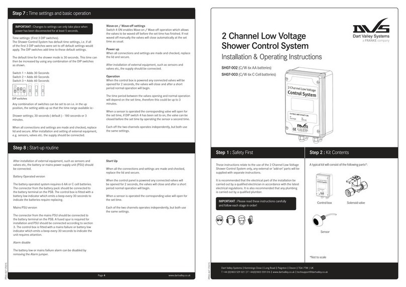
Franke
Franke DVS SH07-002 Installation & operating instructions

Duro Dyne
Duro Dyne DuroZone SMZ-AC quick start guide
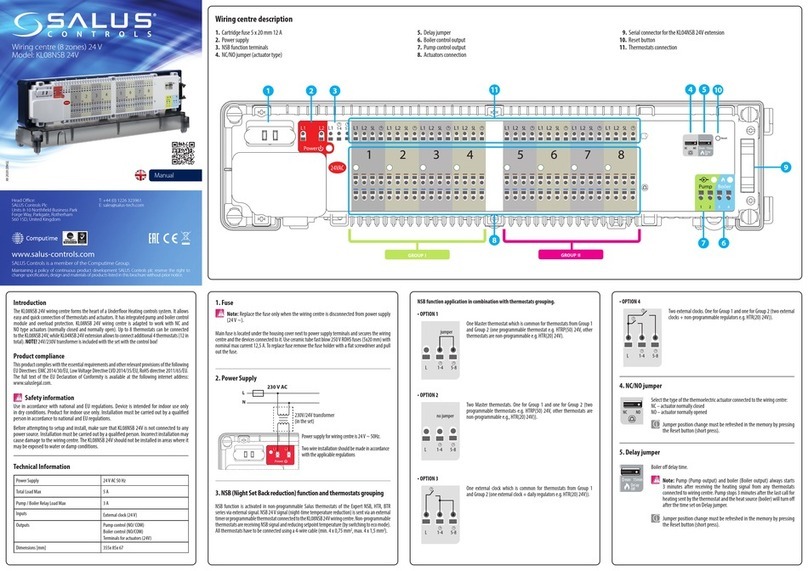
Salus
Salus KL08NSB 24V manual
Next Wave CNC
Next Wave CNC SHARK RS1000 PRO Quick start manual
Thermon
Thermon TraceNet TCM2 Installation, Start-Up, Operating and Maintenance Guide

