Sherline Products WETTROTH 8100 User manual

SHERLINE Mill Digital Readout
P/N 8100 (Inch)
Digital Readouts in the modern machine shop
Digital readouts are popular on full-size shop mills because they make the life of a machinist
much simpler. They make it easier to accurately set or change the table position and eliminate
errors caused by misreading handwheel increments or losing track of multiple rotations. Now
that same convenience is available on tabletop size machines with the availability of a D.R.O.
(Digital ReadOut) for Sherline mills. The kit can be installed on any Sherline mill, regardless of
age. Two-axis kits will also soon be available for Sherline lathes. The compact electronics
package and clever backlash compensation feature were designed by John Wettroth.
On expensive industrial DRO's, a sensor reads a highly accurate external scale. On Sherline's
DRO, the sensor reads rotation of the leadscrew. Because of the accuracy of Sherline's precision
rolled leadscrew threads and the short travels on a machine of this size, this system makes it
possible to provide a DRO with sufficient accuracy while maintaining a price appropriate for a
machine of this size and cost.

The Sherline unit is very easy to use. Remember that the directions of movement of the mill are
referred to as the X-axis (table side-to-side), Y-axis (table in and out) and Z-axis (spindle up and
down). The readout of any axis can be set to zero at any time with the push of a button. From
there as you move the handwheels you can read the table position to three decimal places on the
digital readout. It is not necessary to keep track of the number of handwheel rotations to figure
the stopping point on larger dimensions. This will be especially appreciated when cranking in
"negative" amounts. Backlash can be compensated for by setting it into the unit's electronic
memory in increments of .0005". As a bonus, the package also includes a sensor that reads out
spindle RPM at all times. Three handwheel/encoder assemblies are included with the mill kit.
(The lathe kit includes two.) The length of the connector cables and direction of exit is the same
on all units, so it doesn't matter which is used for which axis.
Installing the D.R.O. components on your Sherline mill
The following instructions describe the steps required to remove the existing handwheels and
thrust collars and replace them with the D.R.O. encoder/handwheel units. It is suggested that you
remove the headstock and motor assembly from the mill to make it easier to install the D.R.O.
components.
1. Move the table all the way to the left. This will help center the leadscrew in the collar and
keep it from binding. (See figure 2.)
2. Move the table all the way to the front toward the operator.
3. Raise the headstock all the way up to the to the top of its travel.
4. Using a 3/32" hex wrench, remove all three handwheels by loosening their set screws and
sliding them off their leadscrews. (If your mill has resettable "zero" handwheels, loosen
the collar locking knob and rotate the collar until the hole lines up with the set screw.
Then use the 3/32" hex wrench to loosen the set screw and remove the entire
handwheel/collar unit.)
5. Using a 3/32" hex wrench, remove the 5-40 screws holding the thrust collars on the X-
and Y-axis leadscrews. Remove the collars.
6. Clean each grooved thrust collar with a solvent like acetone or lacquer thinner to remove
any oil from the surface. (You will later lock them in place in relation to the plastic
housing with "instant glue" and it will not stick to an oily collar.) Using the existing
screws, install new grooved thrust collars on the X- and Y-axes, making sure the
leadscrew is centered in the collar. Make sure the screws are secure, but do not over-
tighten. If a shim washer was present on your existing leadscrew, reinstall it as it was
before.

FIGURE 1-Installing the new thrust collar and existing washer on the X- and Y-axes
FIGURE 2-Makng sure the leadscrew is centered
7. Install a new handwheel and encoder ring on the X- and Y-axes. The encoder ring has
been factory installed on the handwheel for easier assembly. Note that the X and Y
handwheels are similar except on the X-axis, the numbers on the handwheel face away
from the handwheel. On the Y-axis they face toward the handwheel. Make sure the
shoulder at the end of the leadscrew thread is seated against the thrust collar and the
handwheel is pushed in tightly to remove end play before tightening the set screw. On the
X-axis, push the table AWAY from the handwheel while pushing the handwheel onto the
leadscrew shaft. On the Y-axis, hold the table (not the base) with one hand and push the
handwheel onto the shaft with the other. Rotate the handwheel so that the set screw
tightens on a new part of the shaft. If you don't, it will tend to pick up it's old indentation
making it difficult to tighten it in a new position.
FIGURE 3-Detail of the encoder housing showing direction of installation
See Figure 3 for orientation of the encoder housing. The thicker shoulder inside the
encoder should be facing toward the thrust collar. It is easier to tighten the screws if you
install the units upside down with the screws coming down from the top. Place the two
halves of the shell over the thrust collar and over the encoder ring and install the four #2

x 3/8" self-tapping screws. Draw the screws down until they seat snugly, but DO NOT
OVER-TIGHTEN or you can strip the threads! Once tightened into position, the unit can
be rotated around until the screws and cable are on the bottom. When finished, the cable
from the X-axis encoder should come off to the rear, and the cable from the Y-axis
encoder should come off to the right.
*NOTE: The unit should be tight enough so that it doesn't move accidentally once
positioned. If too loose, a spot of "instant glue" can be used to hold the housing in place
on the collar. Another method would be to remove the housing shell and sand the mating
surfaces on a piece of sandpaper on a flat surface until they grip the collar tightly enough.
FIGURE 4-Installing the encoder unit over the thrust collar. The unit is installed upside
down to make it easier to put in the screws. It can then be rotated into position.
FIGURE 5-Rotating the unit into its proper position. (Note: Handwheel/encoder unit not
shown for clarity.)

8. Using a 1/8" hex wrench, remove the flat head screw that holds the Z-axis thrust collar to
the column. Remove the collar by lifting it up and off the Z-axis leadscrew. If the spacer
washer sticks to the bottom of it, remove it and reinstall it on the leadscrew shaft. Then
remove the ball bearing thrust and two washers from the collar and reinstall them in the
new Z-axis thrust collar in the same order. (See Figure 6 below.) Install the new collar on
the leadscrew shaft and secure it to the bed with the flat head screw.
FIGURE 6-Order of washers and bearing in Z-axis thrust collar.
9. Install the larger Z-axis handwheel and encoder unit onto the Z-axis leadscrew. Lift up on
the saddle assembly until the washer and shoulder of the leadscrew are all the way up
against the bottom of the collar.Then push down on the handwheel and tighten its set
screw, being sure to tighten it against a new spot on the shaft. Install the pickup housing
over the handwheel unit as shown in Figures 4 and 5. When finished, the cable should
exit toward the left when viewed from the front.
Installing the RPM sensor
1. Reinstall the headstock/motor/speed control onto the mill.
2. Apply the 2-1/2" round decal to the pulley. A little liquid window cleaner on the pulley
allows the vinyl decal to be repositioned and bubbles squeezed out before it sticks. Once
the liquid is squeezed out and dries, the decal will stick fine.
3. Locate the RPM sensor by holding it in the position shown in Figure 4. Mark the center
of the hole on the plastic belt housing and drill a 1/16" hole. Fasten the sensor to the belt
housing using the self-tapping screw provided. (Do not over-tighten or you can strip the
threads.) A plastic tie-wrap is provided to secure the sensor lead to the motor's power
cord to keep it out of the way.

FIGURE 7-Mounting the sensor to the belt housing
NOTE: If you have a mill with an older AC/DC motor that does not have a plastic belt guard, the
RPM sensor can be mounted in the proper position over the pulley by attaching it to the motor
mounting bracket. Locate and mark where the hole should be drilled. Remove the motor and drill
a hole through the bracket. You can use a self-tapping sheet metal screw or a bolt and nut
through the hole or you can tap the hole to match the thread of the bolt you use.
Hooking up the connecting cables
Plug the cable connector from each encoder unit into is respective port on the display unit. The
telephone type cable connectors go in with the locking tab facing up when the unit is lying on its
back. The RPM sensor cable goes into the port marked "Tach In".
Plug the power adapter into the bottom hole marked "DC In", and plug the transformer into a
115VAC (60 Hz.) source. Check to make sure all three axes are functioning. Turn on the motor
and check to see that the RPM indicator is functioning.
Initializing your display for inch or metric leadscrews
When you press the "Power" button to turn your system on, the upper right corner of the display
will read either "inch" or "metric" mode. Normally, the DRO will be set up properly when you
receive it, but there is always a possibility it could be set wrong. To set or change the system of
measurement your unit displays, follow these steps:
1. With the power off, unplug the power cable from the display unit.

2. INCH-Hold down both the "Power" button and the "X" axis button while you plug the
power cord back into the display unit. After the display comes up, release the buttons.
The display should now read in inch dimensions.
3. METRIC-To initialize your display unit to read metric dimensions, hold down the
"Power" and "Y" buttons while plugging the power cord back into the display unit. Once
initialized, the unit will always read in your chosen system of measurement each time it is
turned on unless you change it.
NOTICE! The Display Does Not Convert Dimensions from Inch to Metric!
The DRO reads rotary handwheel movement and converts it to a linear dimension based on a
formula assuming a certain leadscrew thread pitch. The DRO must be set to agree with the
leadscrews installed on your machine to provide accurate measurements.
The only difference between the inch and metric DRO kits is the number of divisions engraved
into the handwheels. The electronics package is the same for either and can be set to read in
either measurement system depending on the leadscrews of the machine on which it is installed.
Setting the backlash compensation values
To set backlash compensation for each axis, you must first measure to determine what the
backlash is. Use a dial indicator to determine how far the handwheel on each axis rotates before
the table starts to move. (If this amount is excessive, see your instruction manual for instructions
on setting backlash. It should ideally be in the .003" to .005" range.) Once the amount is
determined, the backlash is compensated for by setting it into the display unit's memory. To do
so, complete the following steps for each axis:
1. Turn the handwheel for each axis one full turn. This assures that the software starts the
backlash compensation at the proper initial point.
2. Hold down the "Power" button for longer than a second until the display changes.
3. Now you can set in the backlash for each axis by pushing the button for that axis. Each
time the button is depressed, .0005" (or .01 mm on metric units) is added to the reading.
Set in the amount of backlash you measured previously for each axis. Amounts up to
.015" (.50 mm) can be set. (Note: You cannot cycle backwards to a lower amount. If you
go past your desired amount, you must continue pushing the button until the reading
passes .015" (.50 mm) and returns to zero. Then start over.)
4. Once the backlash for all three axes is set, briefly push the "Power" button again to return
the display to its normal reading. The backlash setting can be checked or changed at any
time by holding the power button until the display changes and resetting the amount.
Once set, backlash settings are held in a special memory chip even if the unit is turned off
and unplugged. They remain until you change them.
Adjusting the Z-axis handwheel screw
To adjust tension on the screw, first remove all Z-axis backlash in the conventional manner by
lifting the motor/speed control unit by hand while tightening the handwheel set screw on a
"fresh" quadrant of the leadscrew to avoid picking up any previous indentations. Once adjusted,
tighten the new center screw only until it is "finger tight". Use a very small amount of Loc-tite®
on the end of the screw to keep it in place. (Do not coat the threads or the screw may become
impossible to remove.) Overtightening the screw will cause the handwheel to become hard to
turn. The purpose of the screw is not to adjust backlash, but rather to keep it from increasing
once it is properly adjusted. Do not try to use the screw to pull out additional backlash. The small
5-40 threads are not strong enough for this task.
A few more tips
When in use, shield the unit from chips so they don't accumulate around the telephone jack
connections on the side. Do not use an air hose clean off the unit.
A metal stand is now included with your DRO so you can stand the unit up on your workbench.
This makes it easier to read while you work. If you wish to secure the box to the stand, a piece of
double-sided foam tape is a good method.
Reversing the direction of the reading on the X-axis
The X-axis readout is designed to read negative numbers when the handwheel is turned in the
clockwise direction and positive when turned counter-clockwise. Should you wish to change
your readout so that it uses a standard x-y plot, you can do so by switching two of the four wires
coming from the encoder for the X-axis.
To do so, unplug the X-axis cable from the readout box. Remove the four screws that secure the
lower housing to the upper housing and then remove the encoder halves from the handwheel. On
the bottom of the half with the encoder is a cover plate secured by three screws. Remove these
screws and the cover plate. This will expose the soldered connections for the four wires coming
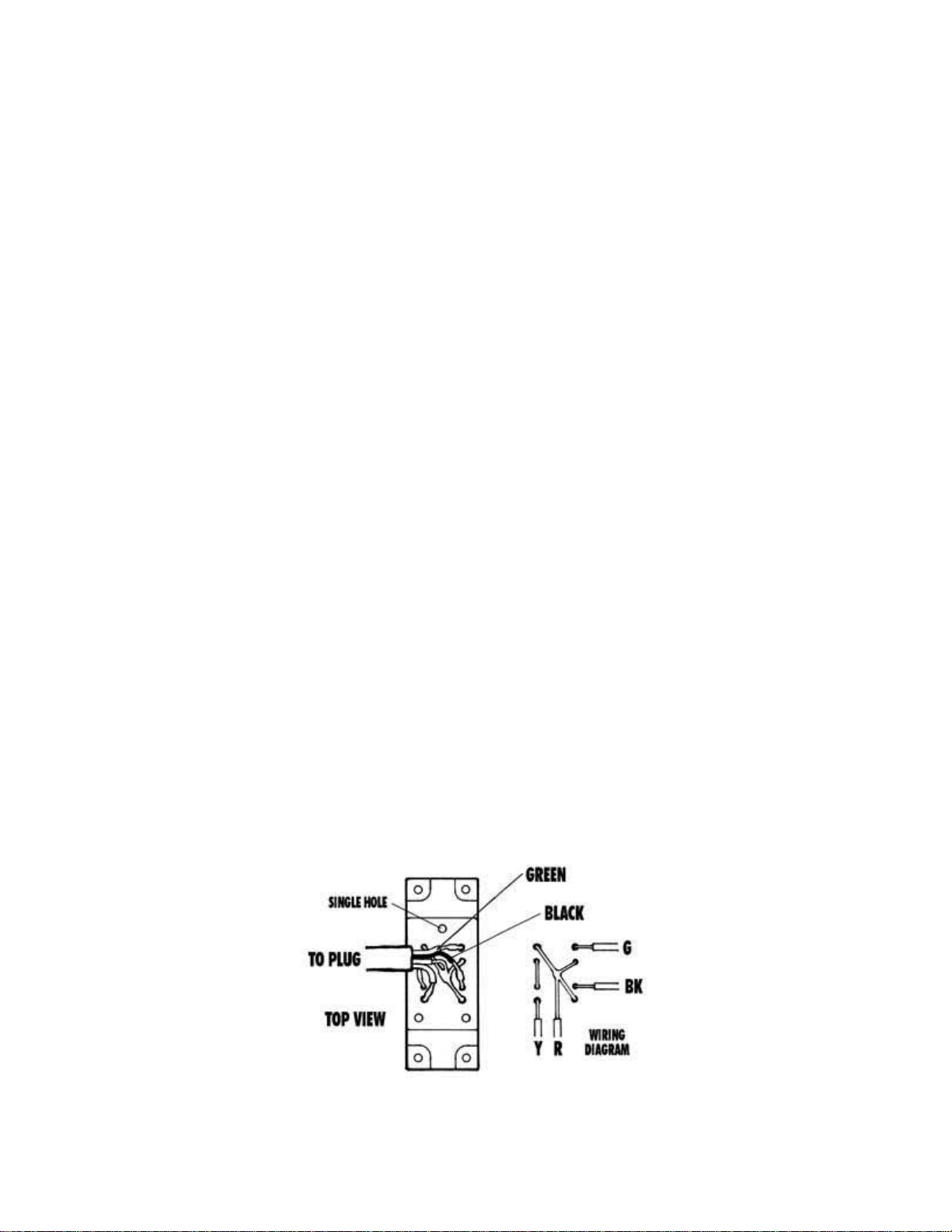
from the encoder. To reverse the direction of the readout, unsolder the green and black wires.
Reverse their position and re-solder to the encoder leads. Reinstall in reverse order. The diagram
below shows the factory locations of the wires before the swap is made.

Encoder housing seen from outside with cap removed. Wires are shown in order as they come
from the factory. (Click on diagram to view a larger version.)
NOTE: The wires and solder joints are small and delicate. If you don't have a suitable soldering
iron and a little expertise along these lines you may return your encoder housing to the factory
and we will make the change for you at no charge. Call first for a return authorization number
and instructions on how to return your housing.
A photo of the X-axis encoder housing with wires as they are attached at the factory. To reverse
the direction of the reading, unsolder and swap the green and black wires and then re-solder and
reassemble. (Click on photo to view larger image.)
Getting the most out of your DRO
When using a machine equipped with a digital readout, I find it is best to use either the readout
or the handwheels, but not both. If the displayed accuracy of .0005" (.01mm) is satisfactory for
the job you are doing, use just the digital readout and disregard the handwheel settings. In cases
where you might want to interpolate to a higher degree of accuracy, the markings on the
handwheels will allow you to do this.
An example of this would be where you have located the center of a bored hole and then changed
the table position. To return the spindle exactly to the hole's center again using the digital readout
could leave you a few ten-thousandths off, which may not be acceptable. In this case, you should
write down your handwheel settings and direction the handwheel was last turned before moving
from the desired location. This will allow you to return to the same spot with great accuracy. The
handwheel marks are .001" or .01mm apart. By reading the space between the marks on the

handwheel and interpolating your position, you can achieve a high degree of accuracy. Knowing
your machine is an important part of achieving this kind of accuracy, and as you get more
familiar with your machine, your accuracy will continue to improve.
Sherline's DRO brings modern machine shop technology down to tabletop size and makes your
Sherline tools easier and more fun to use. I think you will find the digital readout to be a great
addition to your Sherline machine shop.
-Joe Martin, President and Owner
DRO Frequently Asked Questions
Answers from developer John Wettroth
CLICK HERE for a page of answers to the most common technical questions received on the
DRO system. There are also circuit diagrams and pin-out diagrams that may be of help to the
more advanced user.

PARTS LISTING
P/N NO
REQ DESCRIPTION
81010 1 Digital readout box and electronics (complete)
81100 3 Encoder housing w/ encoder wheel and cable
81110 3 Upper encoder housing cap
81300 2 X-axis and Y-axis thrust collars
81310 3 Encoder gear only (comes pressed onto handwheel)
81350 1 Z-axis thrust collar
81320 1 2" X-axis handwheel w/out gear (Numbers face AWAY FROM handwheel)
81330 1 2" Y-axis handwheel w/out gear (Numbers face TOWARD handwheel)
81340 1 2.5" Z-axis handwheel w/out gear (Larger size handwheel)
81500 1 Tachometer encoder w/ cable
81510 1 Tachometer pickup decal
81280 12 #2 x 3/8" Self-tapping screws (DRO housing to upper cap)
40440 1 #2 x 1/4" Self-tapping screw (holds tach housing to belt cover housing)
81050 1 115VAC Power supply/transformer
81150 1 Metal stand for display box
81080 1 Plastic tie wrap
81270 9 2-56 x 3/8" pan head Phillips screw (lower cap to DRO housing)
81200 4 4-40 x 1/4" pan head Phillips screw (Faceplate to spacer on electronics)
81260 4 6-32 x 1/4" pan head Phillips screw (Faceplate plus electronics to box)
41030 1 Z-axis handwheel support screw (Not shown)
Other manuals for WETTROTH 8100
2
Table of contents
Other Sherline Products Industrial Equipment manuals


