Sherwin-Williams ProComp 3800 User manual

309248
Rev. A
TI0875
System 4900
ProComptShown
OWNER’S MANUAL
INSTRUCTIONS
This manual contains important
warnings and information.
READ AND KEEP FOR REFERENCE.
System 3800 and 4900 ProCompt
120V AC 50/60 Hz
System 3800 ProComptwith Three-Stage Turbine
Model 826002
6 psi (41 kPa, 0.4 bar) Maximum Working Pressure
System 4900 ProComptwith Four-Stage Turbine
Model 826003
8 psi (55 kPa, 0.5 bar) Maximum Working Pressure
Model descriptions are in Turbine
Components Table on page 4.
Related Manuals
HVLP–Turbine Gun 309205. . . . . . . . . . . . . . . . . . . . . . .
The SHERWIN–WILLIAMS COMPANY, CLEVELAND, OHIO 44115
ECOPYRIGHT 2000, GRACO INC.
2 309248
Table of Contents
Warnings 2. . . . . . . . . . . . . . . . . . . . . . . . . . . . . . . . . . . . .
General Information 4. . . . . . . . . . . . . . . . . . . . . . . . . . . .
Component Identification and Function 5. . . . . . . . . . . .
Setup 6. . . . . . . . . . . . . . . . . . . . . . . . . . . . . . . . . . . . . . . . .
Shutdown 10. . . . . . . . . . . . . . . . . . . . . . . . . . . . . . . . . . . .
Maintenance 11. . . . . . . . . . . . . . . . . . . . . . . . . . . . . . . . . .
Troubleshooting 12. . . . . . . . . . . . . . . . . . . . . . . . . . . . . . .
Repair 14. . . . . . . . . . . . . . . . . . . . . . . . . . . . . . . . . . . . . . .
Parts Drawing 18. . . . . . . . . . . . . . . . . . . . . . . . . . . . . . . . .
Parts List 19. . . . . . . . . . . . . . . . . . . . . . . . . . . . . . . . . . . . .
Accessories 20. . . . . . . . . . . . . . . . . . . . . . . . . . . . . . . . . .
Specifications 21. . . . . . . . . . . . . . . . . . . . . . . . . . . . . . . . .
Sherwin–Williams Standard Warranty 22. . . . . . . . . . . .
Sherwin–Williams Phone Number 22. . . . . . . . . . . . . . .
Symbols
Warning Symbol
WARNING
This symbol alerts you to the possibility of serious
injury or death if you do not follow the instructions.
Caution Symbol
CAUTION
This symbol alerts you to the possibility of damage to
or destruction of equipment if you do not follow the
instructions.
WARNING
FIRE AND EXPLOSION HAZARD
Improper grounding, poor ventilation, open flames, or sparks can cause a hazardous condition and
result in a fire or explosion and serious injury.
DGround the equipment. See Grounding on page 6.
DIf there is any static sparking or you feel an electric shock while using this equipment, stop spray-
ing immediately. Do not use the equipment until you identify and correct the problem.
DProvide fresh air ventilation to avoid the buildup of flammable fumes from solvents or the fluid
being sprayed.
DWhen flammable liquid is sprayed or used for flushing or cleaning the equipment, the turbine must
be placed at least 20 feet (6.1 m) away from areas where hazardous concentrations of flammable
vapors are likely to occur.
DUse additional air hose if necessary to ensure that the turbine is operated in a clean, dry, well-ven-
tilated area.
DNever place the turbine inside a spray booth! Use this equipment outdoors or in extremely well-
ventilated areas.
DKeep the spray area free of debris, including solvent, rags, and gasoline.
DElectrically disconnect all equipment in the spray area.
DExtinguish all open flames or pilot lights in the spray area.
DDo not smoke in the spray area.
DDo not turn on or off any light switch in the spray area while operating or if fumes are present.
DDo not operate a gasoline engine in the spray area.

309248 3
WARNING
INSTRUCTIONS
EQUIPMENT MISUSE HAZARD
Equipment misuse can cause the equipment to rupture or malfunction and result in serious injury.
DThis equipment is for professional use only.
DRead all instruction manuals, tags, and labels before you operate the equipment.
DUse the equipment only for its intended purpose. If you are not sure, call your distributor.
DDo not alter or modify this equipment. Use only genuine Graco parts.
DCheck equipment daily. Repair or replace worn or damaged parts immediately.
DDo not exceed the maximum working pressure of the lowest-rated system component.
System 3800 ProComptturbine has a working pressure of 6 psi (0.4 bar, 41 kPa).
System 4900 ProComptturbine has a working pressure of 8 psi (0.5 bar, 55 kPa).
DUse fluids and solvents that are compatible with the equipment wetted parts. See Specifications
on page 21 for wetted parts information.
DDo not use hoses to pull equipment.
DRoute hoses away from traffic areas, sharp edges, moving parts, and hot surfaces. Do not expose
Graco hoses to temperatures above 82_C (180_F) or below –40_C (–40_F).
DWear hearing protection when operating this equipment.
DDo not lift pressurized equipment.
DComply with all applicable local, state, and national fire, electrical, and safety regulations.
DDo not point the gun at anyone or at any part of the body.
DDo not put your hand or fingers over the gun fluid nozzle.
DDo not stop or deflect leaks with your hand, body, glove, or rag.
DDo not “blow back”fluid; this is not an air spray system.
DFollow the Pressure Relief Procedure on page 10 if the fluid nozzle clogs and before you clean,
check, or service the equipment.
DTighten all fluid connections before you operate the equipment.
DCheck the hoses, tubes, and couplings daily. Replace worn or damaged parts immediately.
TOXIC FLUID HAZARD
Hazardous fluid or toxic fumes can cause serious injury or death if splashed in the eyes or on the skin,
inhaled, or swallowed.
DKnow the specific hazards of the fluid you are using.
DStore hazardous fluid in an approved container. Dispose of hazardous fluid according to all local,
state, and national guidelines.
DAlways wear protective eyewear, gloves, clothing and respirator as recommended by the fluid and
solvent manufacturer.
DDo not use 1,1,1-trichloroethane, methylene chloride, other halogenated hydrocarbon solvents, or
fluids containing such solvents in the turbine spray system, which contains aluminum and/or galva-
nized-coated parts. Such use could result in a serious chemical reaction, with the possibility of
explosion, which could cause death, serious injury, and/or substantial property damage.

4 309248
General Information
System ProCompt
The System 3800 ProComptand the System 4900
ProComptturbines, compressor, and spray guns can
spray most coatings or finishes currently being used
for automotive refinish, industrial, aerospace, marine,
wood, plastic, and architectural applications.
To produce high-quality paint finishes, the spray gun
typically utilizes inbound air pressure of 6 psi (0.4 bar,
41 kPa) for the System 3800 ProComptand 8 psi
(0.5 bar, 55 kPa) for the System 4900 ProCompt. A
cone of air, produced by the gun, carries and directs
the paint from the gun to the surface, minimizing
overspray and increasing transfer efficiency. This
enables painters to comply with new clean air laws that
are designed to reduce VOC (volatile organic com-
pounds) emissions, eases paint application by requir-
ing fewer paint passes to obtain coverage, and saves
on both material and clean-up time.
See HVLP–Turbine Gun manual 309205 for more
information on the operation and use of the turbine
spray gun.
Unpacking Turbine
Unpack the System ProComptfrom the shipping
carton, and inspect for any possible shipping damage.
If there is any damage, call your distributor.
System ProComptConfigurations
The System ProComptcomes in the following basic
configurations:
DSystem 3800 ProComptthree-stage turbine
sprayer
DSystem 4900 ProComptfour-stage turbine spray-
er
System 3800 and 4900 ProComptTurbine Components Table
System Model 2–qt Remote
Pressure Pot
30-ft (9 m) Turbine
Air Hose
30-ft (9 m) Com-
pressor Air Hose
Gun /
Fluid Set
Extra/Fluid
Sets
System 3800
ProCompt
826002 244357 241413
240071
244118 non-
bleeder style
pressure–fed gun
with 244124 (#3)
244125 (#4)
244126 (#5)
System 4900
ProCompt
826003 244357 241413
240071
244118 non-
bleeder style
pressure–fed gun
with 244124 (#3)
244123 (#2)
244125 (#4)
244126 (#5)
244127 (#6)

309248 5
Component Identification and Function
B
E
G
A
D
C
H
F
Fig. 1
J
K
L
M
TI0876
ATurbine air outlet Connection for turbine air supply to HVLP Turbine Gun (System 4900
ProComptunits include quick connector)
BTurbine power switch ON/OFF switch for sprayer turbine
CStorage compartment Provides storage for fluid set components
DTurbine handle Folds flat for minimum storage space
ETurbine cover Houses air filter and provides dual air flow to motor and turbine
FAir filters (pre-filter and main) Provide filtered air for turbine spray gun and turbine motor
GTwo-speed switch Allows two-speed operation of turbine sprayer motor (used on System
4900 ProComptunits)
HAir filter indicator light Indicates air filter performance and maintenance
JConnector and power cord Provides power for turbine sprayer (power cord provided with turbine)
KResettable circuit breaker Provides protection for turbine motor
LCompressor air outlet Connection for compressor air supply to 2–quart remote pressure pot
MCompressor power switch On/Off switch for compressor

6 309248
Setup
Grounding
WARNING
Improper installation or alteration of the grounding
plug will result in a risk of electric shock, fire, or
explosion that could cause serious injury or death.
This equipment requires a 120V AC, 60 Hz, 15A circuit
with a grounding receptacle. See Fig. 2.
Fig. 2
grounding prong
grounded outlets
Extension cord must be 3-wire, 12 AWG, 50 ft (15 m)
or shorter.
Do not alter the ground prong or use an adapter.
Setup/Use Options
System ProCompthas a variety of user options. See
Fig. 3.
DSee HVLP–Turbine Gun manual 309205 for in-
formation on turbine spray gun setup and operation.
Prepare the Fluid
DAlways strain the fluid before you spray; this
includes color, reducer, and hardeners if used.
DWhen using a turbine spray system, use a slow-
er drying reducer or thinner to compensate for the
faster drying time caused by the warm air of the
turbine. Do not over reduce.
CAUTION
The performance of the turbine sprayer varies with
the viscosity of the material and the length of the
hose. Keep the hose short to prevent pressure drop.
Paint Reduction —Automotive Type Finishes
Reduce and catalyze all paint to manufacturer’s speci-
fications. To compensate for the faster drying time of
turbine systems, use a reducer that is one step slower
than what is used for conventional air spray.
Paint Reduction —Industrial or Domestic
Coatings
Reduce and catalyze all paint to manufacturer’s speci-
fications. If no reductions are given, first thoroughly
mix the fluid to be sprayed. Then gradually mix in the
proper reducer, testing the fluid until you have the
correct spraying consistency.
To test the consistency, remove the stir stick from the
thinned paint. When the paint stream running off the
stir stick breaks into droplets, the first few drops should
be about one second apart.
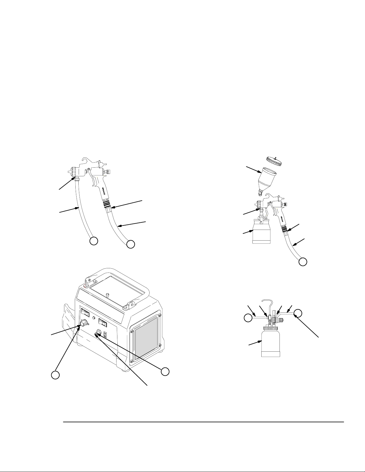
Z
C
A
Fig. 3 04958
K
B
X
A
G
Y
G
C
X
E
F
Y
HJ
E
D
D
cup-over option
(see manual 309205)
cup setup for spray gun
to
compressor
2-quart remote pressure pot
System 4900 ProCompt
remote pressure pot setup for spray gun
TI0875
L
X
Z
309248 7
Setup
Connect the Fluid and Air Supply
See Fig. 3
DThe compressor provides the air supply for the
remote pressure pot.
DThe circled letters in Fig. 3 indicate hose line con-
nections.
1. Connect gun air supply hose (A) between turbine
air outlet (B) and gun air inlet (C). DO NOT use
wrench to tighten connections; hand tighten only.
The System 4900 ProComptturbine uses a quick
connector at outlet (B). A wrench is not required
for hose connection.
2. If using a spray gun cup (D):
Connect the cup to the gun fluid inlet (E).
If using accessory remote pressure pot (F): Con-
nect fluid supply hose (G) between remote pres-
sure pot fluid outlet (H) and gun fluid inlet (E).
Connect pressure pot air hose (J) between pres-
sure pot air regulator inlet (K) and the compressor
air outlet (L).
Connect to Electric Supply
Plug turbine power cord into grounded outlet.
NOTE: Extension cord must be 3-wire, 12 AWG, 50 ft
(15 m) or shorter.
8 309248
Setup
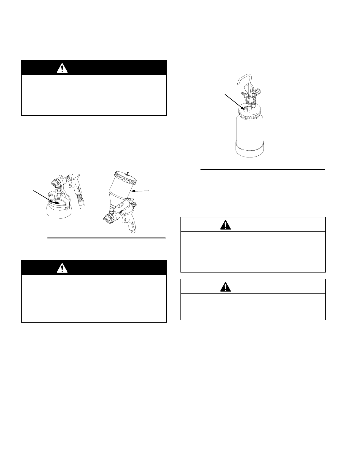
Fill the Cup or Remote Pressure Pot
Spray Gun Cup
WARNING
The spray gun cup is pressurized by the gun’s air
supply. To reduce the risk of serious injury from
pressurized fluid or accidental spray from the gun,
always turn off the air supply to the gun before you
remove the spray gun cup.
Only fill the cup 3/4 full to help keep the air pressure
tube clean, then install the cover. The under-cup cover
has a latch (H) to secure it to the cup. The over-cup (J)
has threads that keep the lid in place when tightened in
place on the cup.
Fig. 4
02845
HJ
Accessory Remote Pressure Pot
WARNING
The accessory remote pressure pots remain pres-
surized until pressure is manually relieved. To
reduce the risk of serious injury from pressurized
fluid or accidental spray from the gun, always
relieve pressure in the pressure pot before you
loosen or remove the cover.
1. Relieve remote pressure pot pressure as follows
(see Fig. 5):
a. Turn off air supply to pressure pot.
b. Turn out pressure relief knob (113) one turn.
Wait until pressure is completely relieved
before you remove cover. Close knob.
Fig. 5
113
2 quart
02882A
2. Remove pressure pot cover and fill. Secure cover.
NOTE: Lightly coat the cover threads with petroleum
jelly.
CAUTION
If the 2-quart remote pressure pot is accidentally
tipped over or held at too great of an angle, fluid may
leak into the air regulator and cause damage. Take
precautions to avoid this. If fluid does get into the
regulator, clean it immediately.
CAUTION
Do not tighten the pressure pot cover more than
hand-tight. Excessive tightening may damage the
cover gasket.
NOTE: Always spray with the least amount of pot
pressure required to provide the desired spray pattern
and rate of application, typically 10 psi. Spraying at
pot pressures higher than necessary wastes paint and
can result in an orange peel finish.

309248 9
Setup
Prepare Surface to be Sprayed
To get proper adhesion, make sure surface is com-
pletely clean.
Operating Turbine
WARNING
Sparks can be expected in the normal operation of
the turbine motor. These sparks can ignite fumes
from flammable liquids, dust particles, and other
flammable substances in the spray area. This can
cause serious injury and property damage. Be sure
to follow the precautions below:
DWhen flammable liquid is sprayed or used for
flushing or cleaning equipment, the turbine must
be placed at least 20 feet (6.1 m) away from
areas where hazardous concentrations of
flammable vapors are likely to occur.
DUse additional air hose if necessary to ensure
that the turbine is operated in a clean, dry, well
ventilated area.
DNever place the turbine inside a spray booth!
Use this equipment outdoors or in extremely
well ventilated areas.
DAvoid all ignition sources such as: static elec-
tricity from plastic drop cloths, open flames like
pilot lights, hot objects like cigarettes, arcs from
connecting or disconnecting power cords, and
turning light switches on and off. Extinguish or
remove all sources of ignition.
1. Turn turbine ON a few minutes before spraying to
allow warm-up.
NOTE: When the turbine is not in use for an extended
period of time, turn it off. The turbine does not shut off
automatically.
2. Be sure turbine filter is clean before operating. See
page 11 to check and clean filter.
NOTE: To adjust the spray gun pattern see the turbine
gun manual.
System ProComptCompressor Cold
Weather Operation
The System ProComptuses a diaphragm compres-
sor. A new diaphragm may be stiff in cold weather. If
cold enough, the diaphragm is too stiff to allow the
compressor motor to start (the unit hums). If this
occurs, follow these steps:
1. Turn compressor OFF. Turn turbine ON and allow
to warm up for a few minutes.
2. Turn compressor ON. If compressor does not
start proceed to step 3.
3. Turn turbine and compressor OFF.
4. Unplug turbine from power source.
5. Loosen four thumbscrews (16), remove filter
retainer (15), prefilter (22), and main filter (21).
6. Hand spin cooling fan on compressor for a few
revolutions.
7. Reinstall filters and filter retainer.
8. Plug in turbine.
9. Turn turbine and compressor ON. If necessary,
repeat steps 3–9 above.

10 309248
Shutdown
Pressure Relief Procedure
WARNING
PRESSURIZED EQUIPMENT HAZARD
The equipment stays pressurized until pressure is
manually relieved. To reduce the risk of a serious
injury from pressurized fluid, accidental spray from
the gun, or splashing fluid, follow the Pressure
Relief Procedure whenever you
DAre instructed to relieve the pressure
DStop spraying
DCheck or service any of the system equipment
DInstall or clean the fluid nozzles
1. Turn off air supply to gun.
2. Turn off turbine sprayer.
WARNING
The turbine hose outlet may be hot. Carefully check
the hose end before you remove the hose.
3. If using remote pressure pot, relieve pressure by
following the pressure relief procedure on page 8.
NOTE: Elevate spray gun and pull trigger. This will
allow fluid in fluid hose to drain back into remote
pressure pot.
4. If using a spray gun cup:
Unlatch cup cover; loosen or remove cup from
cover to relieve cup pressure.
5. Clean spray gun and cup as instructed in the
HVLP–Turbine Gun manual 309205.

309248 11
Maintenance
Daily
The turbine systems are lifetime lubricated. The only
maintenance required is filter cleaning and replace-
ment.
The turbine filter must be clean at all times to provide
sufficient air flow to cool motor and atomize the fluid.
Check turbine pre-filter (22) daily for cleanliness.
Check the main filter (21) weekly, minimum. Clean as
necessary.
NOTE: To check filter, turn on turbine and place piece
of paper against pre-filter. If air intake holds paper in
place, filter is okay.
The System 3800 and 4900 ProComptsprayers have
an air filter indicator light on the front panel. If the filter
is good the light is out. If the filter is clogged or has low
airflow the light will come on as in Fig. 6 below.
Fig. 6 8049A
To clean filter:
1. Turn off and unplug turbine.
2. Loosen four thumbscrews (16), remove filter
retainer (15) and pre-filter (22). See Fig. 7.
3. Remove main filter (21) and clean by using one of
the following three methods:
DTap filter gently on flat surface, dirty side
down.
CAUTION
To prevent damage to filter, do not use compressed
air on a wet filter.
DDirect compressed air (100 psi [7 bar, 70 kPa]
maximum) through filter panel in the opposite
direction of arrows on side of filter (from the
clean side to the dirty side).
DSoak filter for 15 minutes in water and mild
detergent. Rinse filter until clean. Air dry. Do
not use compressed air on damp or wet filter.
WARNING
To avoid damage to the turbine and possible elec-
tric shock, never install a damp filter in the turbine.
CAUTION
To keep out dirt, do not operate the turbine sprayer
without both filters installed.
Fig. 7
16
21
22
15
20
1
TI0877
Weekly
Check hose for cracks, leaks, and holes. Replace if
necessary.
Annually or Every 600 Hours, Whichever
Comes First
Replace motor brushes 600 hours after turbine sprayer
operation. If brushes are not replaced, motor failure
will occur.
NOTE: It is recommended that an authorized service
center perform the motor brush replacement procedure
on page 16.

12 309248
Troubleshooting
PROBLEM CAUSE SOLUTION
No fluid delivery No material, no remote
container pressurization, hose
or pickup tube clogged
Check container for material.
Check for leaks at the container gasket (2-quart
pressure pot cover. Tighten cover if loose.
Check for air flow from male quick-disconnect at
compressor outlet (should be approx. 1/4 CFM).
Turn pressure regulator clockwise. Look for pressure
on gauge. (If no pressure on gauge, check air line and
fittings).
Check hole in 2-quart pressure pot cover at needle
valve. Clean if necessary.
Check for obstructions.
Check if fluid pickup tube is unplugged. Tighten.
Blow out and clear material hose.
Compressor not
starting
Cold weather operation See System ProComptCompressor Cold Weather
Operation on page 9.
Turbine not starting No power Check outlet for power. Cycle red rocker switch.
Check that correct IEC (modular) cord is used and
plugged in.
Check circuit breaker(38). Push to reset.
Poor atomization Dirty filter Clean filter.
Extension cord too long Extension cord must be 3-wire, 12 AWG, 50 ft (15 m)
or shorter.
Hose too long Replace with shorter hose. See Accessories page 20
for shorter hose and Part No.
Circuit breaker trips Filter clogged Clean filter and replace as necessary.
High ambient temperature Move turbine to cooler area.
Excessive brush wear Remove cover and turbine, and check for free motor
rotation and for brush wear. Replace motor brushes if
necessary.
Excessive current draw Return to authorized service center.

309248 13
Notes

14 309248
Repair
WARNING
Turn off turbine and unplug power for the following
procedures.
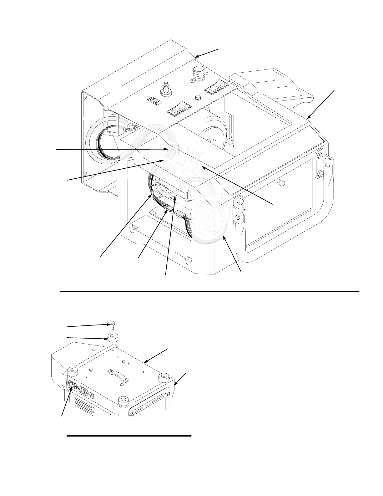
Turbine Sprayer Disassembly (unless
otherwise indicated, refer to Fig. 8 and
Fig. 9).
1. If necessary, clean and replace filter according to
maintenance procedure on page 11.
2. Loosen the four thumbscrews (16), remove the
filter retainer (15) prefilter (22) and main filter (21).
See Parts Drawing on page 18.
3. Disconnect the air hose (84 ) from the “out”side of
the compressor (64 ).
4. Disconnect the compressor wiring harness (a)
from the compressor (64 )
5. Remove the four cap screws (27) and bumpers
(7).
6. Place the turbine on it’s back. Carefully separate
the turbine cover (1) from the turbine baseplate (2)
while guiding the compressor air hose (84) and
wiring harness (a) through the air passage (b) in
turbine cover (1). Place the turbine baseplate
upright on a work surface.
7. Repair or replace items as required.
8. After completing servicing place turbine baseplate
(2) on its back.
9. Slide turbine cover (1) onto turbine baseplate
approximately 1–2”(to get it started).
10. Reaching between the turbine cover (1) and base-
plate (2) carefully guide the compressor air hose
(84) and wiring harness (a) through air passage (b)
through the compressor mounts (c) in the turbine
cover (1).
11. Gently pull the free ends of the compressor air
hose (84) and wiring harness (a) with your other
hand to take up the slack.
12. Maintain tension on the compressor air hose (84)
and wiring harness and slide the turbine cover (1)
fully onto the turbine base plate.
13. Replace four capscrews (27) and bumpers (7).
14. Reconnect compressor air hose (84) and wiring
harness (a).
CAUTION: Keep excess tubing and wiring clear of
compressor cooling fan (d) by securing to compressor
mount (c) with wire tie.
15. Reassemble filter, filter retainer, and prefilter.
309248 15
Repair
Fig. 8 TI0911
64
d
a
84
b
c
e
1
2
7949A
Fig. 9
27
7
1
2
A
Power Cord Replacement
Replace power cord by unplugging from IEC connector
(A). Install new cord. See Fig. 9

16 309248
Repair
Motor Brush Replacement
NOTE: It is recommended that this procedure be
performed by an authorized service center.
1. Use Turbine Sprayer Disassembly procedure on
page 14 to take turbine apart. Use Turbine/Motor
Replacement on page 16 to replace turbine.
2. Remove plastic fan cover.
3. Remove brushes. Check commutator for exces-
sive wear.
Note: Do not install new brushes in a turbine in which
the commutator has been damaged by the brush
holders. A motor with this type of damage cannot be
repaired.
4. Install new motor brushes using reverse order.
Keep lead wires from all rotating parts and motor
frame.
CAUTION
Do not run the motor with the air inlet or outlet
sealed off.
5. Reassemble turbine.
6. Run motor 30 to 45 minutes at half-rated voltage
to seat motor brushes.
Note: If half-rated voltage is not available, run repaired
unit in series with another turbine for 30 to 45 minutes.
Turbine/Motor Replacement
The System 3800 and System 4900 Turbines each use
a different turbine/motor. See the Turbine/Motor Re-
placement Kits in the Parts List on page 19 for a
listing of replacement kit parts.
See Parts Drawing on page 18.
1. Use Turbine Sprayer Disassembly procedure on
page 14 to take turbine apart.
2. Remove turbine gasket (25).
3. Remove 3 screws (6).
4. Remove plate (82) and 3 spacers (83).
5. Remove turbine motor wires from spade connec-
tors.
6. Rotate turbine (24) from outlet fitting (18) and lift
up from turbine spacers (23).
7. Install new turbine gaskets (25 and 41).
8. Reassemble turbine.
9. Connect ground wire to turbine housing as re-
quired.
10. Reconnect wires according to applicable turbine.
See Fig. 10, or Fig. 11 schematics.
Fig. 10
System 3800 ProCompt
Fig. 11
System 4900 ProCompt

309248 17
Notes

18 309248
Parts Drawing
28
27
10
12
13
14
1
25
82
24
19
18
446
47
5
32, 40
42
39
36
37
4
34
33
31
6
27
7
68
67
38
65
41
23
83
6
29
81
26
6
20
21
22
15
64
26
27
6
74
72
16, 17
86
85
87
84

309248 19
Parts List
Ref
No. Part No. Description Qty
Ref
No. Part No. Description Qty
1 276674 COVER, turbine 1
2 192775 BASE PLATE, turbine
(System 3800) 1
192774 BASE PLATE, turbine
(System 4900) 1
3 192786 PLATE, retaining 1
4 106084 SCREW, pan hd 4
5 192787 DUCT, turbine 1
6 112117 SCREW, cap, hx hd 8
7 113817 BUMPER 4
10 114064 PLUG, inlet 1
11 114065 PLUG, inlet, female 1
12 114410 SCREW, pan hd, torx 6
13 244166 LID, tool box 1
14 197054 FOAM PAD, tool box 1
15 197057 RETAINER, filter 1
16 192895 SCREW, captive 4
17 158486 O-RING 4
18 192779 FITTING, outlet 1
19 156698 O-RING, buna–n1
20 192789 GASKET, filter 2
21 240273 FILTER, main, paper 1
22†240274 FILTER, pre 1
23 192780 SPACER, turbine 3
24* 240270 TURBINE KIT, 3 stage; 120 volts
(System 3800) 1
241122 TURBINE KIT, 4 stage; 120 volts
(System 4900) 1
25 193059 GASKET, turbine (System 3800) 1
192788 GASKET, turbine (System 4900) 1
26 192784 BRACKET, handle 2
27 114531 SCREW, cap, hx hd 8
28 113414 NUT, lock 2
29 192785 HANDLE, turbine 1
31 114658 SWITCH, rocker (System 4900) 1
32 114279 SENSOR, pressure 1
34 114293 SWITCH, rocker, red 1
36 111593 SCREW, grounding 1
37 102063 WASHER, lock, external tooth 1
38 114403 BREAKER, circuit; 15A, 120V 1
39 192905 PLATE, deflector 1
40 193059 GASKET, sensor 1
41 192845 GASKET, duct 1
42 192846 GASKET, duct 1
46 114287 FITTING, barbed 1
47 192810 HOSE, air 1
50 244118 GUN, HVLP (not shown) 1
51 241413 HOSE, air, 30 ft (not shown) 1
52 240071 HOSE, compressor, air, 30 ft
(not shown) 1
53 103473 STRAP, tie (not shown) 1
54 244125 FLUID SET, #3 (System 3800)
(not shown) 1
244123 FLUID SET #2 (System 4900)
(not shown) 1
64 244231 COMPRESSOR kit, 120V 1
65 114302 CORD SET, 15 ft 120V 1
65 241998 CORD SET, 10 ft (System 3800) 1
240281 CORD SET, 15 ft (System 4900) 1
67Y193095 LABEL, danger 1
68Y193096 LABEL, warning 1
69 193126 LABEL, caution 1
75 244122 #2/4/5/6 ACCESSORY KIT
(System 4900) Not shown 1
81 114538 SCREW, mach, pan hd 2
82 194094 PLATE, turbine 1
83 SPACER, turbine
194096 System 3800 3
194097 System 4900 3
84 197284 TUBE, air 1
85 197153 FITTING, valve, barb 1
86 244135 VALVE, duckbill 1
87 101936 NUT, jam 1
†Pre-filters are available in 5 packs. Order Part No.
240274.
* Turbine Brush Kits are also available. Order part
number240546
YExtra danger and warning labels are available
for free.

20 309248
Accessories
2-Quart (1.9 liter) Pressure Pot 244357
50 psi (345 kPa, 3.5 bar) Maximum Inlet Air Pressure
2-quart (1.9 liter) capacity, aluminum cup.
Includes air pressure regulator, gauge, pressure relief
valve, and rigid hook handle.
WARNING
Do not use 1,1,1-trichloroethane, methylene chlo-
ride, other halogenated hydrocarbon solvents, or
fluids containing such solvents in the turbine spray
system, which contains aluminum and/or galva-
nized-coated parts. Such use could result in a
serious chemical reaction, with the possibility of
explosion, which could cause death, serious injury,
and/or substantial property damage.
102
103
101
112
02951A
123
122
121
119
118
114
120
124
126
127
*109
128
109
(Handle is
shipped loose,
inside of 2-qt
container.)
Ref.
No. Part No. Description Qty.
101 M70672 PRESSURE GAUGE Kit 1
102 M70727 SAFETY VALVE 1
103 104815 PRESSURE REGULATOR 1
109 M71144 POT, 2 quart (1.9 liter), aluminum 1
112 M71425 GASKET KIT, polyethylene (5 pak) 1
114 M70725 FITTING 1
118 169969 QUICK DISCONNECT, male 1
119 M71491 HOSE, fluid; 60 in. long; 1/4 in. ID 1
120 240063 HOSE, air; 54 in. (1.37 m) long 1
121 M70854 HOSE CLAMP 1
122 110440 FITTING. tee 1
123 189557 RESTRICTOR 1
124 M70399 QUICK DISCONNECT, male 1
127 M70402 QUICK DISCONNECT 1
128 M72842 FITTING, air pressure stem 1
DSee HVLP Fine Finish Systems brochure
300564 for all accessories.
DNon-Silicone Lubricant 111265 (4 oz) is available
for fluid seals and wear areas.
NOTES:
This manual suits for next models
3
Table of contents
Other Sherwin-Williams Paint Sprayer manuals

Sherwin-Williams
Sherwin-Williams SUPERNOVA 820-002 User manual

Sherwin-Williams
Sherwin-Williams ULTIMATE 824-030 User manual

Sherwin-Williams
Sherwin-Williams 820169 D Series User manual

Sherwin-Williams
Sherwin-Williams ULTIMATE NOVA 1000 User manual

Sherwin-Williams
Sherwin-Williams 820-169 Series B User manual

Sherwin-Williams
Sherwin-Williams NOVAspx 824-012 User manual

Sherwin-Williams
Sherwin-Williams PT2500 User manual

Sherwin-Williams
Sherwin-Williams ULTIMATE Plus+ 1000 User manual

Sherwin-Williams
Sherwin-Williams 820-001 User manual

Sherwin-Williams
Sherwin-Williams 820-206 User manual


