Sherwin-Williams ULTIMATE NOVA 1000 User manual
820"
Rev.
B
SUPERSEDES
Rw.A
Thii
manualcontainsimportantWarnings
and
Insuuctions.
Read
the
rnanua! and
keep
it
for
rsference.
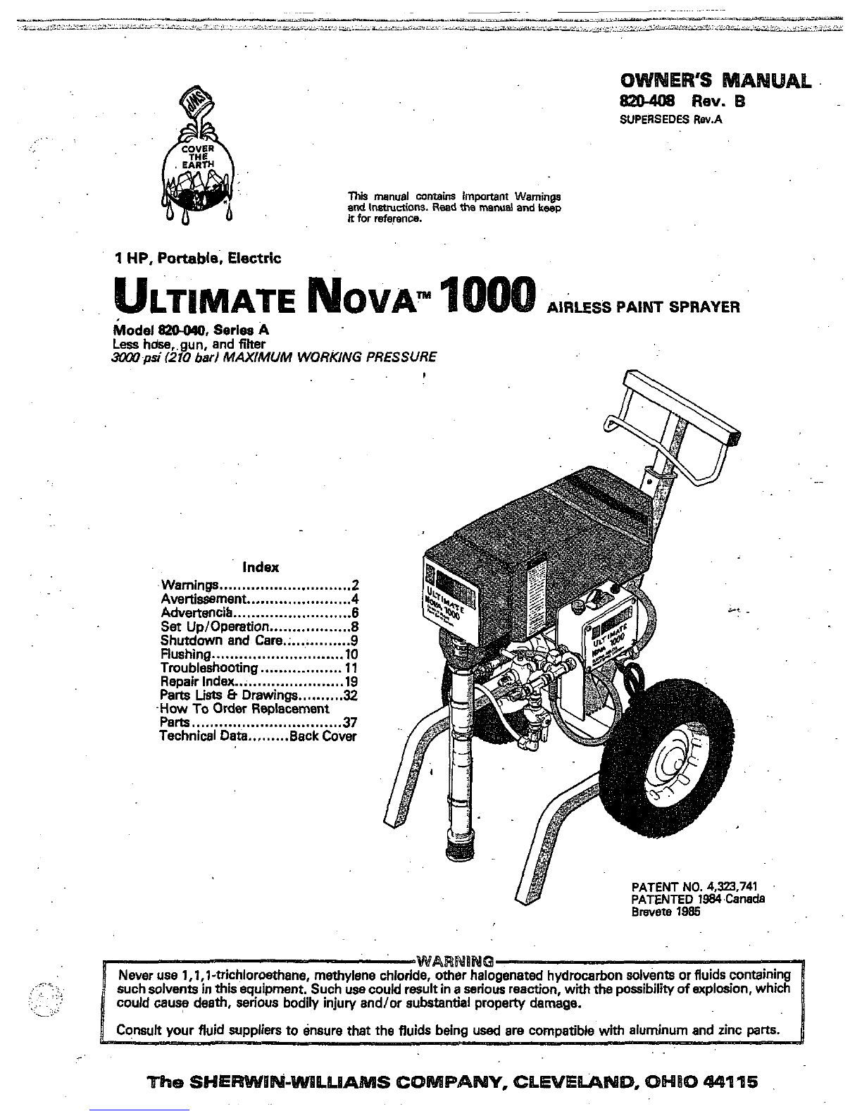
1
HP, Portable, Electric
..
LTIMATE
AIRLESS
PAINT
SPRAYER
Model
W,
Series
A
Less
hdse,.gun. and filter
SzW
psi
(210
bad
MAXIMUM
WORKING PRESSURE
Index
.Warnings...
.........................
.2
Avertissarnent
.......................
4
Advertencih
.........................
.6
Set
UptOperation
..................
8
Rushing
.............................
10
Tmubleshooting
..................
11
Repair index
.......................
.lS
-How
To
Order
Replacement
Parts
Lists
8
Drawings
32
Shutdown and Care.;
.............
9
..........
Parts
................................
.37
Technical
Data
.........
Back Cover
PATENT NO.
4,323,741
PATENTED
1984,Canada
Brevete
1985
_.*.
i
.I
,,
.
:,
....
....
,:.
.A
-
..
Consult your fluid suppliers
to
ensure that the fluids being
used
are compatible with aluminum and zinc
parts.
%IS
equlpment%nerates very highfluidpressure. Sprayfrom
thegun,leaksorrupturedcomponents
can
inject fluid
through yourskinand into your body and
cause
extremely
serious bodily injury,includingthe need for amputation. Also,
fluid injectedorsplashed into the
eyes
can
cause'serious
damage.
NEVER
poim
the
spray
gun
at anyone
or
at
any paq
of
the
body.
NEVER
put hand or fingers over the spray tip.
NEVER
try
to "blow back" paint; this is NOT an air spray system.
nerd
Safe
ALWAYS have thetip guard in place.on thespray
gun
when
spraying.
beforecleaning or removing
the
spray tip orservicingany
ALWAYS follow
the
Pressure Relief Procedure,
below,
systemequipment.
NNER
try
to
stop or deflect leakswith your hand or body.
before each
use.
Be
sureaquipmentsafetydevicesareoperatingproperly
?!
TB
edi
I
rmtmetnt
any
UI
amears
to
Denetrate vour skin.
aet
B
sJe
JI
gun
s%*E2Zare operating prop& before
each
use.
Do
not remove or modifv anv
Dan
of
the
wn:
this
ra
G
n
8af
can
cause
a
malfunction and result'in
&Nous
bodilykju.ry.
Safety
Latch
the
gun
safety latchin the closed or
"safe"
position. making
'Whenever youstop spraying, even for
a
moment, always
set
the
gun
inoperative. Failure
to
set
thesafety latchcan resultin
accidental triggering of the gun.
Diffuser'
Te
gun
diffuser breaks up spray and reduces
the
risk of injec-
hon
when the tip
is
not installed.Checkdiffuseroperation
regularly.Followthe Pressure
Relief
Procedure, below,
then
remove the spray tip. Aim the
gun
into
a
metalpail,
pmsure. trigger thegun.
If
thefluid emitted
is
not
diffused in-
holding the
gun
firmly to the pail. Using the
lowest
possible
to an irregular stream, replace the diffuser immediately.
nip
Guard.
ALWAYS have the tip guard in place~onthe spray
gun
while
spraying. The tip guard alerts youto the injection hazard and
helps prevent accidentally placing your fingers or anypanof
your body dose
to
the spray tip.
a
Ti
Safe81
e&&
cautio when cleaning or changing spray tips.
If
thespray tip clogs whilespraying, engage thegunsafety latch
immediately.ALWAYS follow the Pressure
Relief
Pro-
cedure
and
then removethe spray tip toclean
it.
NEVER
wipe
off
build-up around the spraytip
until
pressure
is
fully relieved and the gun
sa+ty
latchis engaged.
e
thegun safetylatch.
(51
Hold
prensura.
(61
Engage
the
gun
If
YOU
suspect
that the
spray
tip
or
hose
is
completely dogged,
or
that
pressure
has
not
been
fully relieved
after
following
the
Steps above.
VERY
SLOWLY loosen
the
tipguard retainingnutor hose end coupling and relieve pressure gradually,then
loosen
completely.
Now
dear the tip or hose.
pi
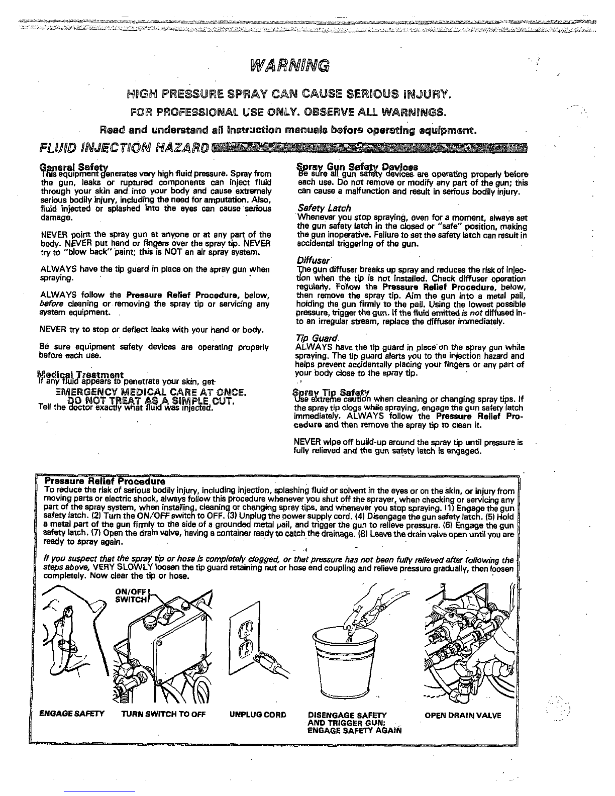
ENGAGE
SAFETY
TURN
SWITCH
TO
OFF
UMPLUG
CORD
DISENGAGE
SAFEW
AND
TRIGGER GUN;
ENGAGE
SAFEW
AGAI~~
OPEN
DRAIN
VALVE
..
GEtPed
$Pf&Y
Anymisuse of the sprayequipmentoraccessories,such
as
overpressurizing, modifying parts, using incompatible
.
.,
chemicals end fluids, or usingworn ordamagedparts,can
cause them to ruptureand result in injection or other serious
..
bodilyinjury,fire.explosionorpropertydamage.
could cause
it
to malfunction.
NEVER alter or modify any part of this equipment; doing
so
worn or damaged
parts
immediately.
CHECK
all
sprayequipmentregularlyandrepairorreplace
Read
andfollow thefluidand solvent manufacturer's literature
regardingthe
use
of protectiveclothingand equipment.
$WEm
h@SSMU@
Thb
sprayercandevelop
3aW
psi
(210
b8rJ
MAXJMUM
accessoriesarerated to withstand the maximum working
WORKING
PR€SSURE
Be
sure that all
spray
equipment and
pressure
of
thissprayer. DO NOT exceedthe maximum work-
system.
ingpressure of anycomponentoraccessoryused in the
Wuid
Compatibility
BE SUREthat
all
fluids and solvents used are chemically com-
patible
with
the wetted parts showninthe Technical Data
on
the backcover.Alwaysread the fluid andsolvent manufac-
turer's
literature before usina themin this spraver.
h
Static electricity
is
created by the high velocity flow of fluid
throughthe pump and hose. If every partof the spray equip-
ment is not properly grounded, sparking myoccur, and the
when plugginginor unplugging
a
power supply cord. Sparks
systemmaybecomehazardous.Sparkingmayalsooccur
dust panicles and other flammable wbstances;whether you
can ignite fumes from solvents endthe fluid being sprayed,
are spraying indoors or outdoors, and.cancause
a
fire or
ex-
plosionandseriousbodily injury and property damage.
Always plug the sprayer inM an outlet
at
leest
20
feet
I6
ml
away from
the
sprayer and the spray area. Do not plug in or
unplug any powersupplycords inthespray area when there
is
any chance of ignitingfumes
still
in the air.
while using this equipment, STOP SPRAYING IMMEDI-
If
you experience any static sparking oreven
a
slight shock
ATELY.Check the entiresystem for positive grounding. Do
not
us8
thesystem againuntilthe problem has been identified
and corrected.
Grounding
To
reduce
the risk
of
staticsparking, groundthe sprayer and
all
other spmy equipment used or located
in
the sprayarea.
CHECK yourlocalelectrical defor detailed groundingin-
structiom foryour area and type of equipment. BE SURE to
ground
all
of this spray equipment:
1.
Sprayer: plugthepowersupplycord,orextensioncord,
each equippedwithan undamaged three-orona ulug.into
-
..
tension cords must have three wires and be rated for
15
a
properly grounded outlet.
Do
not
use
anadapter.ex-
amps.
HighPressurefluid in the hoses
can
be
very d~KIerous.
If
the
2,
F/ujdhoses:
use
only
groundedhoses with
a
maximum
of
hose develops a leak, split or rupturedue
to
any kindof wear.
damageormisuse, thehighpressuresprayemitted from
it
tan
5M)
feet
I150
ml combinedhoselength toensureground-
causaan iniectioniniurvorotherseriousbodilviniurvornrc-ingcontinuity.Refer to
Hose
Grounding Contlnulty.
perty
dam&
.
,~~~
3.
Sorev
nun:
obtainoroundinothrouahconnection to
a
ALL
FLUID
HOSES
MUSTHAVE SPRINGGUARDS1The pioper6grounded fhidhe-and spkyer.
springguardshelp protectthe hosefrom
kinks
orbends
at
or
4.
obieecr
being
sprayed:
according
to
local
code.
close to the couplingwhich can result in hose rupture.
TIGHTEN
811
fluid connections murelybeforeeach use, High
5.
A//
so1V&7r
Pat7swhenflushing,according to local
pressure fluid candislodge
a
loose coupling
or
allow high code. Useonly metalpails,which
are
conductive. Do not
pressure sprayto
be
emitted from the coupling. placethe pail on
a
non-conductive
surface,
such as paper
or cardboard, which interruptsthe grounding continuity.
NEVER
use
a
damaged hose. Before each use. checkthe en-
tirehoseforcuts,leaks,abrasion, bulgingcover,ordamageor
&
To
m8intah
groundins
COntinuiV
Whenflushing
OrdkV-
exist, replace the hose immediately. DONOT try to recouple
movementof the hose.couplings.If anyoftheseconditionsingpressure,always hold
a
metalpart of thegunfirmly
to
the side of
a
groundedmetalpail, then trigger the gun.
highpressurehoseormend
it
with tape oranyotherdevice. A
~~Ms&p
s,fey
repaired hose cannot contain the high pressure fluid.
HANDLE
AND
ROUTE
HOSES
CAREFULLY
.D~
not
pull
o~
.
byfo!owing
.the
specificflushingproceduregiven
on
page
10
Reducethe
risk
of injectioninjury, staticsparking, or splashing
hasas
toequipment.
Do
not
use
fluids
o;
which
ofthismanual. Follow
the
Pressure Rellef Procedure on
are not compatible with the inner tubeandcover ofthe hose.
''
and
the
'pray
tip
before
flu*in6"
Hold
a
metal
(82°C) or below
-4OOF
I4!'C).
DO
NOT
expose
G~~~
hose
temperinures
above 1m-F pa*of thegunfirmly to the side of
a
m-1
pail anduse the
lowest
possiblefluid pressure duringflustiing.
Hose
G~~nding
Continuity
~~~~~~
PARTS
HAZARD
Proper hosegroundingcontinuity
is
essentialto maintaining
a
air and fluid hoses
at
least
once
a
week. Ifyourhosedoes not
~ .
body parts. KEEPCLEAR of moving parts when starting or
groundedspraysystem.Checktheelectricalresistanceof your Movingpans can pincii oramputate.yourfingersorother
have a tag
on
it
which specifiesthemaximumelectrical operating the sprayer.Unplug
the
sprayer,and follow
.the
mau'rnum resistance limits. Use
a
resistance meter in the ap- tingaccidentally.
resiaence, contact the hosesupplierormanufacturer for the PressureRelief Procedure
on
page
2
toprevent
it
from star-
propriate range for your hose to check the resistance.
If
the
resistanceexceeds the recommendedlimits,replace
it
im-
mediately. An ungroundedor poorly groundedhose can make
yoursystemhazardous;Alsoread
FIRE
OR
EXPLOSION
HAZARD.
.
....
.I
...
..i
.,
..
.
..:
IMPORTANT
ticutariy the General Standards, Part 1910, and the Construction Standards,
Part
1926-should be consulted.
United States Government safety standardshave been adopted undertheOccupational Safetyand HealthAct.
Thee
standards-par.
Coutsignes
g6n6ralm
de
securite
pulv4risti par
le
pistoiet
ou
iefluidesous pression pmvenant de
Cet
appareii produit un fluida
B
trh
haute pression.
LB
fluide
fuiies
ou
de ruptures peutpBnhrsous ia peau ou
B
I'intBrieur
du corpset entraher des blessurestdsgraves, voir
mBme
une
sant ou entrant dans.
les
yauxpautaussientrainerdes
amputation. MCma sans
We
sous
pression. ie fluide Bclabous-
blessures graves.
NE
JAMAIS pointer
ie
pistoietvars quelqu'un ou vers une par-
tie
quelconque du corps.
NE
JAMAIS menre
ia
main
ou
les
doigts sur I'ajutage du pulvdrisateur.
NE
JAMAIS essayarde
meumatique.
"refouiar"
ia
peinture.
Cet
appareil Nest PAS uncompresseur
TOUJOURSgarder
la
protectionda I'ajutage en piace sur
le
pistolatpendant
la
puivbrisation.
TOUJOURS observer la March
B
Suivre pour DBtendre la
Pression donnbaplusloin. .avant de nettoyer ou d'aniaver
que sur una partie de I'appareil.
I'ajutage du puivdrisataur,oud'effactueruntravailquaicon-
NE
JAMAIS essayerd'arrCtar oude dbvierles fuites avec
la
main
ou
ie corps.
Avant chaque utilisation, bian s'assurer que ies dispositifs de
sBcuritB fonctionnent correctement.
Boins
~mBdic~X
En
cas de pbnbtratlon de fluide sous
la
peau:
DEMANDER
IMMEDIATEMAENIT
DES
SQIMS
MEDICAUX
D'URQERICE.
Dire axacternent au medecin qual type
ae
iiquida
a
Bt6
inject&
UME
SIMPLE
CQUPURE.
Dispositifs
de
sbcurit6
du
pistolet
de &curit6 du pistoietfonctionnent corractament:Nepas
Avant chaque utiiisation, bien s'assure que tous ies dispositifs
enlevar
ni
modifier une partiaquelconque du pistoiet: ceci
ris-
queraitd'antrainerunmauvais fonctionnement
et
des
blessures graves:
NE
PAS
memm
cm~
BLESSURE
COW"
A chaque fois que I'on s'arr6ta de puhrdriser, mCme
s'il
s'agit
Verrou
de sdcuritd
d'un courtinstant,toujoursmettre
le
verroude skuritb du
empschar ie pistolat de fonctionnar. Si la varrou deSeCuritB
pistoletsur
la
position"fermbe" ou"sBcurit6"
l"safe"1
pour
n'est pas rnis,
le
pistolatpeut
se
dkiencher accidanteiiement.
Diffuser
Le diffusaur du pistolet
seti
B
diviser lejet
et
B
r&uire
les
ris-
quesd'injectionaccidantellequandI'ajutagen'estpasen
place.VBrifier
le
fonctionnament du diffuseur r6guiihramant.
Marche
B
Suivre pour DBtendre la Pression donn6eplus
Pour cettevBrification,dhtendre
la
pressionanobservant
ia
+ns
un
seau en mhi,
en
le
maintenant fermementwntre
le
loin puis enlever I'ajutage du pulvBrisateur. Pointer
ie
pistolet
seau.Puis,en utiiisant ia pression
la
plus faible possible, ap-
puyer
sur
la
gachette du pistolet. Si le fluida projet4
n'estpas
diffuse sous
forme
de jet irrdguiier. remplacer immediatement
le
diffusaur.
TOUJOURS maintenir laprotectionde I'ajutage an place sur
le
Rotection de I'ajutage
pistolet du pulvbrisateur pendant
la
puldrisation.
La
protec-
tion de I'ajutage attire I'attention sur ias risques d'injection
et
contribue
B
Bviter que lasdoigts ouune partie quelconque du
I'ajutage du pulv6risateur.
corpsnepasseaccidenteilement
B
proKimit6immediatede
@Mk6PISs'WN
bmsiqnes
de
a6curit6
concwnmt
1'@,4tagB
du
Faire extr&nemant attention
B
I'occasion du nettoyage ou du
rempiacementdesajutagesdupulv6risateur: Si I'ajutage
se
verroudesBcurit6dupistolat.TOUJOURS bian Observer
la
bouchependant
ia
pulv6risation.
mettre
imrn4diaternant
ie
Marche
B
Suivre pour DBtendrela Pression puis enlever
I'ajutage du pulvdrisateur pour ie nettoyer.
NE
JAMAISassuyer ce qui
s'est
accumulhautourde I'ajutage
jupulvbrisateuravantque
la
pression
ne
soit
completement
tombee
et
qua le vermu de&curite du pistolat ne
soit
engag6.
ies blessures-par injection de fluide ou cell@ causeeS pard'kla boussant
ou par 6lectrocytion,toujounbien observer cena marche
B
suNre
B
cha-
emplacement des ajutages
et
d'una manihre gBnBrale
B
chaque
an&.
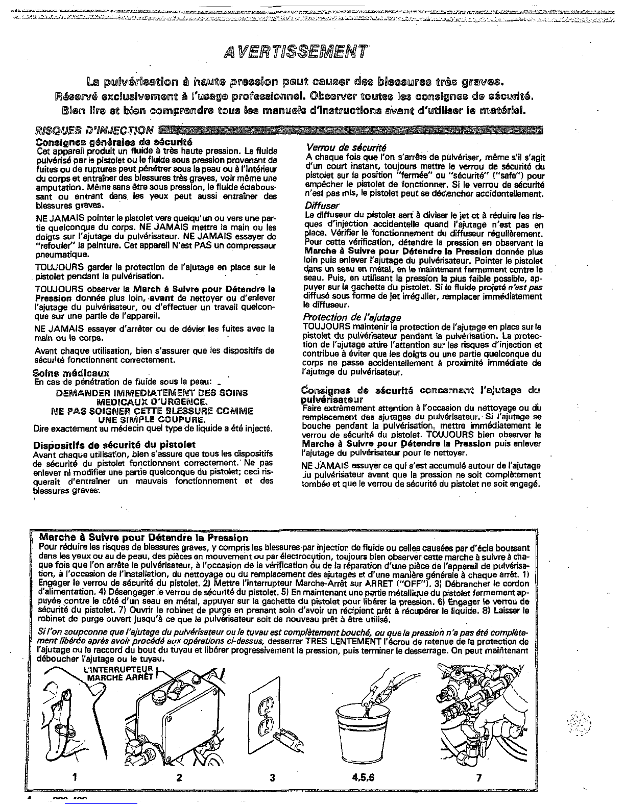
11
la
vdrification oude
la
r6paration d'unepikade I'appareil de puivbrisa-
nterrupteur Marche-Arrit sur ARRET
("OFF").
31
DBbrancherle cordon
pistolet.
51
En maintenant une partie metalliqua du pistolet fermement ap-
r
le gachettedu pistoietpour iibBrer la pression.
6)
Engager leverrou de
ur soit de nouveau pr8t
B
&re
utilis6.
prenant Soin d'avoir un recipient prdt
B
r6cup6rer ie liquide.
81
Laisser la
Sil'onsoupconneque
menr
Jib&e
apr& emir
I'ajutage ou
ie
raccordd
3
4.5.6
7
R!SWfES
EN
CAS
DE
~AU~~n$E
UUULUSAUOON
DU
MAUERjEk
Cmsignes
g6n6uales
$0
sQcuritpB
Toute utiiisation,anormale de I'appareil de pulvBrisation ou des
Puessi
n
aaessoires
domrne,
per example, ia mise sous une pression
Ce
pulvfrisateur peut produire unePRESSION
MAXIMUM
DE
excessive.Ies modificationsdepieces,I'utilisationde produits Bl6mentsduPulv6risateUr
et
ses
accessoiressontconcuspour
TRAVAIL
210
bar
f3cX7V
Ib/po.2).
Sassurerque tous
les
chimiqum et dematieresincompatibles
et
I'utilisation de rbister
B
la
pressionmaximum detravail dece pulvbrisateur.
pi& udesou abim6es peut causer des dBg8ts
B
I'appareil ou
des ruptures de piket entrainer une injection deliquideou NE PAS d6passer
la
pression maximum de travail d'aucun dss
46ments ou accewires
utili&
avec cet appareil.
d'autresblessures drieuses, un incendie,uneexplosionou
bm
slet
cAi~ni~~
88
cou
d'autrm
d6gAts.
BlEN!'A&URERqueTous
fes
corpfdessolvantsutilishs
NE JAMAIS alt6rer ou mod#ier une piece de cet appareil; ceci sont chimiquement compatibles avec
les
Parties mouillbas
in-
risquerait d'enuainer
son
mauvais fonctionnement. diqubes dans ies
"Donn6es
techniques", au
dos
de
la
couver-
VERIFIER r6gulihrementtout I'appareil de pulv6risation et
ses
du
fabricant desfluides
a
utilisb
avant
de
Sfen
servir
ture. Toujours lire soigneusement
18s
documents
et
brochures
6quipements
et
r6parer ou remplacerimmddiatement
Ies
dans
~
pulvBrisateur,
,
pihsus& ou abim6es.
MEWRES
DE
SEWROUE
CONCERNANU
LE$
TUYAUX
FBEXIBLES
Le
fluide
B
hautepressioncirculantdans
les
tuyauxpeut&repar tout autrem'oyen.
trk
dmgereux.
En
cas defuitesur letuyau, mame minuscule,
de fissure,dbchirureourupture
B
la
suitedeI'usure,ded6gats
MANIPULER
LES
TUYAUX
ET
fluide sous pression.
oud'unernauvaise utilisation,
les
projectionsde fluide haute
.
CHOISIR
solGNEUsEMENT
LEUR
Ne
pas
d6placer
PreFSion qui en proviennentpauvententrainerdesbl-ur-
le
fluide
en
rent
sur
le
Ne
ws
utiliser
defluides
ou
de
gravespar pendtratbnsous
la
pew
oupar contactt.ainSique
qui
ne
pas
compatibles
aYBC
I~enVeloppe~in.
des d6ghmat6riels.
TOUS
LES
TUYAUX
FLEXIBLES
'DOIWENT AVOlR
DES
destempdraturessuphrieures
B
82°C(169°F)ouinfbrieures
B
!
tBrieureou endrieure dutuyau.NEPASexpcser
le
tuyau
B
RESSORTS SPIRALE
DE
PROTECTIONI
Lesspiralesde
4'C
(4°F).
boucles ou de nosuds sur
18s
tuyaux quipourraient entrainer
la
'
Une
benne
cont,nu#
Je
la
JTa
wrre
&
tuyeux
protection contniuent
B
biter
la
formation depliures,de
Gonainuiite
dQ,la,
,a,ter
dss
vu
8ux
SERRERFERMEMENTtousIes racmrdsavantchaqueutilisz-vaporisation.VBrifiez
ia
rkistance 6iectriquedevos Waux
h
rupturedu tuyau
B
I'endroitduraccordou
B
sonvoisinag6.essentiellepourmaintenir
la
mise
B
laterredeI'ensamblede
tion. Le fluide souspression peutfairesauterunraccord
desserr6 ouproduireunjet
B
haute pression s'6chappant par
le
fluides
et
B
air, a.u moins une fois par semaine. Sivotre tuyau
raccord.quemaximum,prenez contact avecle foumimur detuyaux
ne comporte pes d'etiquene qui prBcise
ia
rbistance Blectri-
NE
JAMA~S
utiliser un tuvau endommagb. Avant chaw Utiliser
un
metre
de
r6sistence
de
la
gammeappropride
pour
ou la fabricant pour avoir
les
limitesde Aistance maximum.
coupur-. fuitm. abrasions.boursouflur= de renveloppdou
limiteS
recornmand6es,
remplacez
le
tuyau
immwiaternent.
utiliiation, verifierentihrementchaquetuyaupourdeceler
les
~tretuyau
et
v6rifiaz
dshnce,
si
ceile-G
dBpasse
ies
route
am
dBt6riorationoujeudesraccords. Si I'on constate
Un
tuyau
san~
Fisc
a
terre
ou
avec
une
la
twre
incor.
rune de
cas
detBriorations,
iJ
fautremplacer le tuvauim-
reae
peut
dm
~sques
pour
VOtre
systeme.
,jsez
mbdiatement. NEPASessayerderefaire
le
raccordd'un tuyau
LES
RISQUES
D,INCENDIE
ou
DzmPLOSION
ci-dwus,
haute pressionnide rbparer le tuyau avec duNbanadhbifou
RISQUES
~1~~~~~~E
OU
WEXPLO$lON
De I'6lectricitB statique
est
produitepar le passage du f1uide.B
grande vitesse dans
la
pompe
et
dans
ies
tuyaux. Sitoutes
Ies
2.
Tuyaux flexibles: Afin d'assurer
la
continuit6 de
la
mise
B
la
pikes de I'appamil de pulv6risation ne sont pas convenable term, n'utiliser que des tuyaux comportant une mise
B
la terre
etavantunelongueurmaximumcornbin&de
1%
m
ment reli6es
B
la
masse ou
a
la
terre, des Mrncelles peuvent se
produire
et
I'appareilrisque &&re dangereux.Des hinceiles tinuit6ducircuit de mlse
B
la
terre des tuyaux".
(1500pieds).Sereporter6galementauparagraphs
"Con-
Peuvent balement seProduire
i
I'occasiondubranchemem
3.
mstolet:
~~~li~~~
la
&
la
terre
en
le
raccordant
un
sontsuffisantespourallumerles vapeun de wlvants
et
le
oududbbranchemantducordond'alimentation.LesBtincelies
tuvau
fle~ble
et
+,
un
pulv6risateurdeja
convena~ment
reli&
fluidepulvdris6,
les
finesparticulesdepoussihreainsique
B
ia
terre.
d'autres substances inflammables, quend on pulv6rise
B
I'in-
t6rieur ou
B
I'extBrieur. et elles oeuvent causer un incendie ou
4.
Objets, mat.4rid
ou
surfacesrecevant
la
puldrisation:
observer
le
code ou les dalementations
locales.
..
..
..
..
...
..
..
~.
uneexplosion.
ainsi
quedesblessures gra~ketdes db@ts
trouvant
B
au moins
6
m
(20
piedslde I'appareil
et
de I'endroit
matbriels. Toujoun brencher
le
pulvdrisateur dans une prise
se
oh
se
fait
la
pulv6risation. Ne pas brancher ou d6brancher un
cordon
d'alimentation quei qu'il
soit
dans
la
zone
oh
se fait
la
pulv6risation quand
il
y
a
lemolndrerisquequedesvapeurs
encore prbsentes dans I'air prennent feu.
ressentez lamoindredbcharge, ARRETR IMMEDIATEMENT
S'il
se produit des 6tincelles d'6lectricitB statique, ou si vous
LA
PULVERISATION. VBrifiez aue
le
sWheentier
est
bien
mis
B
la terre. Ne vous servezpaidu syaiheavant que
le
pro-
bldme soit identifie
et
corrigd.
fiWh
la
tWPe
QU
&
la
lllaS88
Pour r6duire iesrkquesde productiond'Btincelles d'BlectricitB
statique,
le
pulvbrisateureitous
les
6quipementsutilidsou
se
tmuvent dans
la
zone de pulvbrisation doivent&re relis
B
la
termou
B
la
masse. Pour connaitre le detail des instructions de
mise
B
la
terredans
la
rdgion et
le
type
particulier d'Bquipe
ment, CONSULTER le code ou
les
rdglementations Blectriques
tion suivants sont bien rell6s
B
la
terre:
locales.
S'ASSURER que tous Ies 6quipements de pulvbrisa-
rallongequidoivent &reBquipBs d'une prise
B
3
fiches en bon
1.Pulvdrisateur:Brancher
le
cordond'alimentation
ou
la
&at,
.dam uneprisede murant convenablementmise
B
la
terre. Ne pasutiliserd'adaptateur. Toutes
les
rallongesdoivent
avoir
3
fils
et &re pr6vues pour 15 amp8res.
5.
Tousles
saaux
de
solvantsutilis& pour
le
rincage: observer
mdtalliques conducteurs de I'Blectricite.Ne pas mettre leseau
le code ou ies rbglemenmtions locales.N'uMserque des
seaux
sur une surface non conductricecomme.sur du papier ou du
carton
carcela interrompreit
ia
continuit6
le
lemise laterre.
6.
Pour
conserver la continuit.4 de
la
mise
B
la
terre quand on
rince le
mat6riaI
ou
quand on
lib*
la
pression, toujours
contre
le
cbt4 d'unseau en
m.4td
puis appuyer sur
la
d6tente
maintenir une partle metaliique dupistoietfermement appuy6e
du pisfolet.
ou d'autres parties du corps.
SE
TENlR
A
L'ECART des pieces
Les pieces en mouvement peuventpincerou couper
185
doi
enmouvamentpendant
la
miseen route
et
la
marchedu
pulv6risateur.Pour Bviter un d6marrageaccidentel,,debran-
cher
le
pulvBrisateur
et
IibBrer
la
pression avant d'effectuer des
MPORTAWT
arations.
&B
adoptBes en vertu de
la
Loi sur
la
SBcurit6 et
la
Sam6 au
Lees
nomes de s6curitB du Gouvernement des Ems-Unisont
Travail.
Ces
normes
et,
particulidrement, ia Section 1910des
Normes
GBn6rales ainsi que
la
Section 1926 des Normes de la
Construction, doivent atre consult&.
Rnswm
DUS
AUX
PECES
EM
~~~~~~~~~
..
Fun43E5
Seeguridad
general
Este
equipogeneraunfluidoaunapresi6nmuy
alta.
0
rociado delapistola.
10s
escapesdefluido
o
roturasde
los
wmponentes pueden inyectar fluido
en
la piel
y
el
cuerpo
y
causar lesiones earemadamente graves, incluyendo a veces
la
necesidad de amputaci6n. Tambih.
el
fluidoinyectado
o
salpicado
en
10s
ojos
puede causar graves daflos.
NUNCAapuntarlapistolahaciaalguien
o
algunapartedel
quilla. NUNCA tratar de "hacer retornar la pintura";
este
NO
cuerpo. NUNCA colocar la mano
o
10s
dedos encima de
la
b-
es
un
sistema de rociado de aire.
SIEMPRE tenercolocado
el
protectordelaboquillaenla
pistola mientras
se
est6
pulverizando.
SlEMPREseguir elprocedimiento dedescarga depresi6n.
servicio a cualiquier equipo del sistema.
dado
m&
abjo.
antes
de limpiar
o
Sacar
la
boquilla
o
de dar
NUNCA tratar de parar
0
desviar los'escapes con la mano
o
ei
cuerpo.
edn
funcionando bien antes de cada uso.
Asegurarquetodos
10s
aparatosdeseguridaddel.equip0
Tratamiento
mddico
Si pareciera que un.poco de fluido.penar6 la piel, conseguir
TRATAMllENTO MEDICO
DE
UROENCIA
DE
INMEDIATO.
NO
TRATAR
LA
HERIDA
@DM0
UPJ
SIMPLE
CORTE.
Deciralmedicoexactamentecua fluido fue.
Aparatos
de seiuridad de
Ira
pi5tOl~3
pulverized&
Asegurar que todos
ios
aparatosprotectoresdelapistola
estsn
funcionandobienantesdecadauso. No scar
ni
modificarninaunaoiezadelaoistola Dues oodrla causar
el
malfuncionamlento
be
la misma
con
iasconsiguientes [miones
personalas.
Pestillodeseguridad
Cada vez que
se
deje de pulverizar, aunque
sa8
por
un
breve
momento.siemprecolocarel pest" deseguridaden
la
posici6n"cerrada".
Io
quedejala pistolainoperante. El
no
hacedo puede llevar
al
disparo imprevisto de la pistola.
Difusor
8
difusor de la pistola dispersa el chorro pulverizado
y
reduce
el
riesgo de inyeccidncuando
no
est6
instaiadalaboquilla.
el
procedimientode descaigadepresi6n. dado rnhsabajo.
Revisar con reguiaridad
e1
funcionamiento del difusor. Seguir
mat6lico.sosteni4ndolabien firm contra
61.
Utilizando
ia
y
despub sacarlaboquilla.Apuntarlapistola
a
unbalde
emitido
no
sale disperso
en
un
chorro irregular, reemplazar
de
presi6n
m6s
bajoposible,disparar ia pistola. Si
el
fluido
inmediato
el
difusor.
Rotactor de la boquilla
pistola mientras
se
est6
pulvenzando. Este protector llama
ia
SIEMPREtener
e1
protector
de
laboquillacolocado
en
la
atenci6n contra el peiigro de inyecci6n
y
ayuda a prevenir
la
colocaci6n accidental de
10s
dedos
o
cualquier otra partedel
cuerpo cerca de la boquilla.
Sagupidad
de
la
bcqullla
pulverizadcra
Tenermuchocuidado
al
limpiar
o
cambiarlasboquillas.
Si
pestiilo
de
la
pistoladeinmediato.SIEMPREseguir
el
pio-
llegara
a
obstruirse mientras est6 pulverizando; enganchar
el
quilla para limpiarla.
cedimiento de descarga de presl6n
y
despub Sacar
la
bo-
NUNCA limpiar
la
acumuiacibn
de
pintura alrededor
de
la
bo-
quiilaantes
i13
quesehayadescargado por cornpleto
la
..esidn
y
el
pmillo
est6
enganchado.
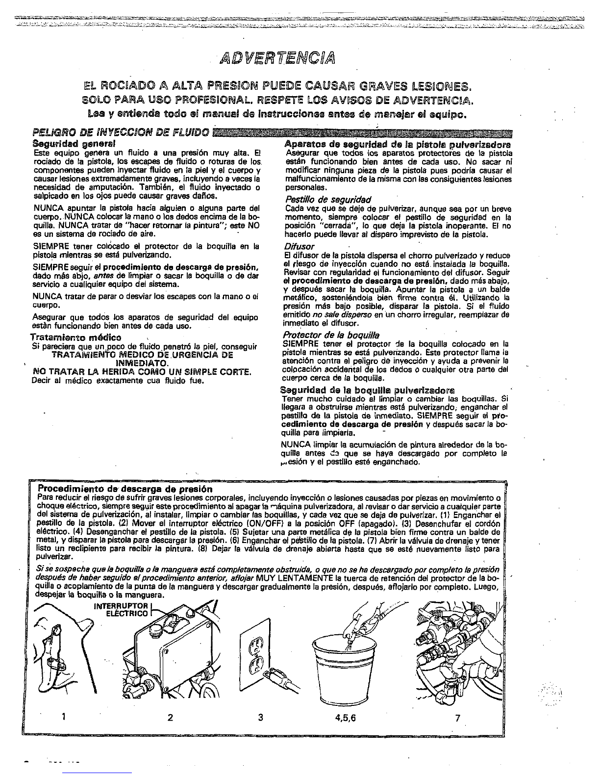
Procedimiento dedescarga de
presi6n
choqueel6ctriw, Siempreseguir esteprocadimiento al apagarla T6quina pulverizadora,
al
revisar
o
dar servicio a cualquier parte
Para reducir el riesgo desufrir graves iesiones corporales, incluyendo inyecci6n
o
lesiones causadasporpiezas
en
movimiento
o
del sistema de pulverizaci6n.
al
instalar, limpiar
o
cambiar Ias boquillas,
y
cada vez que
se
deja de pulverizar.
11)
Enganchar
e1
elhrico.
(4)
Desenganchar
el
pesu'llo
de
la pistola.
15)
Sujetar una parte mdlicade la pistola bien firme contra
un
balde de
Pestillodelapistola.
(21
Mover
e1
intenuptorelbctrico
ION/OFF)
a
laposicibn
OFF
(apagadol.
I31
Desenchufar
el
cord6n
metal,
y
disparar la pistola para descargar la presi6n.
161
Enganchar
e1
perstilio de lapistola.
17)
Abrir la vhlvula de drenaje
y
tener
pulverizar.
list0
un
reclipientepararecibirlapintura.
18)
Dejarlav6lvuladedrenajeabiertahastaque
se
est6nuevamente iisto para
SiSesospacha
que
la
boquila
o
la
mnguera estd
qutlla
o
acoplamiento de la pun- de la man
despuhs de haber seguidoelprocedimiento
despajar la boquilla
o
la manguera.
,..
. .
.. ..
.. .
'
.
:.
.,
..
..~.
"ERRUPTOR
2

PELhGRO
POR
MAL
US0
DEL
EQUPO
segws~ded
gpwasal
Cualquler mal
us0
de(
equipo pulverizador
o
10s
accesorios. tal
como ~brepresurizaci6n.modificaci6nde piezb,
UM
de
matenales
y
pmductos quimicosincompatibles,
o
utiliuaci6n
y
causenlainyecci6ndefluido
u
otraslesionescorporales
graves, incendio, explosi6n
o
daiion a
la
propiedad.
NUNCA alterar
o
modficar ninguna pieza de este equipo; el
hacerlo podria causar una averia.
REVISAR con regularidad el equipo pulverizador
y
reparar
o
reemplazar de inmediato las piezas daiiadas
o
desgastadas.
PwiOn
del
sietema
Esta
pulverizadora puede desarmllar
210
barlas
WM
psi) de
PRESION
DE
TRABAJOMAXIMA.Asegurarquetodoel
equip0 pulverizador
y
sus
accesorios tienen la capacidad para
aguantar ia presi6n maxima de trabajo de esta pulverizadora.
NOexcederla presi6n maximade trabajodeningrlncom-
ponente
o
acmoriode mesistema.
Cornpatibilldad
de
Fluid0
ASEGURARque todos
10s
fluidos
y
saiventesusadosson
en.la hoja de datos tbcnicos en la contratapa. Siempre lee las
quimicamente compatibles con
las
piezasmojadas ilustradas
instruccionesdelfabricantedelfiuido
y
sulvente antdde
usarlos
m
esta pulverizadora.
El
fluido
que pasa a aka presidn por18s mangueras puede ser
muy
peligroso. Sien la manguera se desarrolla unescape
pe-
desgaste. daiio
o
maitrato,
el
chorro a aka presi6n emitido por
queiio.unarotura
o
rajaduradebidoacualquier tip0 de
alli
puede causar una lesi6n por inyecci6n
u
otraslesionscor-
porales graves
o
deiion a la propiedad.
lTODAS
US
MAMGUERAS PARA FLUIDOSTIENEN
QUE TENER GUARDAS
DE
RESORTEI Estas protegen las
tos
o
cerca de ellos,
10s
que podrian traducirseen roturas de le
mangueras contra dobleces
0
retoreeduras en
10s
acopiamien-
manguera.
Antes de usarlas, APRETAR bien firmes todas las conexiones.
o
dejar que por
bt
escape un chorro a aka presi6n.
Elfluido
a
alta presi6n puede desalojar
un
acoplamiento sueito
NUNCAusarunamangueraque
e&
daflada.Siempre.
revisarlaen buscade cortaduras,escapes, abrasih, cubierta
abultada,
o
acoplamientos sueltos
o
datiados. Sillegara a en-
contrarse cualquiera de mascondiciones,reemplazar dein-
mediato la manguera. NO intentar reacoplar una manguera de
aha presibn
o
enmendarla con cinta adhesiva u otro material
Ruido a akapresi6n.
similar.Una manguera que ha sido remendada no aguante el
MANEJAR
Y
PASARCUIDADOSAMENTELAS
MANGUERAS.Notirardelasmanguerasparamoverel
equipo.
No
usarfluidos
o
solventesquaSean incompatibles
con ei tubo interno
y
la
cubierta dela manguera. NO exponer
4'C
(-4O'F).
lasmanguerasatemperaturassobre 82°C
(180OF)
o
bajo
Continuidad
de[
EIPCM~FO
ola.puesta
8
tierpa
de
la
manguara
esencialparamantenerconectadoatierraelsistema
La continuidaddelcircuit0depuestaatierraapropiado
es
pulverizador.
Es
indispensablerevisarlaresistencia elktrica
vsz a
la
semana. Si la manguera no tiene una etiqueta en la
maxima de Ias mangueras de aire
y
de fluidopar
lo
menos una
cual se especifica le resistencia eltktrica maxima, ponerse en
contact0 con el proveedor
o
fabricante de la manguera para la
resistencia en lagama apropiada para comprobar la resisten-
informaci6n sobre
10s
limites de resistencia. Usar un metro de
mediato.
Es
muy arriesgado tener una manguera sin puesta
a
cia; si excede 10s limitesrecomandados,reemplazarlade in-
tierra o'conla puesta a tierra en malas condiciones. Leer tam-
bi6n la informaci6n sobre RIESGO DE INCENDIO
0
EXPLO-
.~.
depiezasdaiiadas
o
desgastadas,puedehacenqueserompan
SEGUR!DAD
EN
EL
us0
DE
BAS
~~~~U~~~S
. ...
SION.
ds
amba.
..
.i
:
PBBGW6
DE
8NCENDlO
8
EXPLO$lOM
El
flub a
alta
velocidaddelRuidoal .pasar
por
labomba
y
mangueracreaelectricidadest6tica.Sitodas 18s panesdel
equipopulverizador no tienenbuena tierra.puedenocurrir
chispas, convirtiendoai sistemaen algopeligmso. Tambibn,
d6nel6ctrico. €staschispas puedeninflamar
los
vaporesde
pueden producirse chispas a1 enchufar
o
desenchufar
el
cor-
10s
solventes
y
ei chorro de fluido puiverizado, panicuies de
polvo
y
otrassustancias infiamabies,
sea
alaire libre
o
bajo
techo;
Io
que podria causar una explosidn
o
incandio
y
graves
Iesiones corporales
y
dafios
a
la propiedad. Enchufar siempre
la pulverizadora a
un
tomacorriente quese encuentre a por io
rociar. No enchufar
o
desenchufar ningrln cord611 elbctrico en
menos
6
m
(20
pies)delamhquina
y
dd
Area
que
88
va
a
posibilidadde que queden vapor- inflamables en el aire.
ellugardondeseest6rociandocuandotodaviaexista
ia
Si se observa alguna chispa esthtica,
o
se siente
el
mas
leve
choqueelbctrico. APAGAR DE INMEDIATOLA
PULVERIZADORA. Revisar todo el sistema en busca de con-
exi6n
a
tierra positiva. No usarnuevamenteelsistemahasta
haber ubicado
y
corregido el problema.
Para reducir el riesgo de chispas esthticas. conectar a tierra la
se encuentre en el iugar que se va a rociar. CONSULTAR el
pulverizadora
y
todo el otro equipo de pulverizar que se use
o
c6digo elbctrico de la localidadpara las instrucciones sobre
IBS
conexionesatierraexigidasparalazona
y
tip0 deequipo.
pulverizador:
ASEGURARdeconectara tierratodo esteequipo
1.
Pulverizadora: enchufar el cord6n elbctrico,
o
cable exten-
sor, cada uno con unenchuf de tres patas en buen estado,
a
un tomacorriente con puesta a tierra apropiado. No usar un
adaptador. Totos
10s
cables extensores tienen que tener tres
hilos
y
una capacidad de
15
amperios.
,
2.
Mangueraspara
fluidos:
usarsolamentemanguerascon
puestaatierradeuna longitud combinadade
150
m
tambiknalphrrafosobre continuidad a tierrade.la
(500
pies), para asegurar buena continuidad
a
tierra. Referirse
3.
pistola:hacerlapuesta
a
ti.erraconecthndola
a
una
manguera.
manguera de fluido
y
puiverizadora bien conectadas
a
tiena.
4.
Objeto
que
$e estd rociando: de conformidad con el cddigo
local.
5.
Todos
10s
baldes de solvente usados durante el lavado, de
meta4 que,sesnconductivos.
No
coiocarelbaldeenuna
conformidedconelc6digolocal.Usarsolamentebeldes.de
superficienoconductiva,comopapei
o
cartbn,queinter-
rumpe
la
continuidad
a
tierra.
6.
Para
mentener la continuidada tierra duranre
el
lavado
o
descarga de presidn, siempre apoyar una parte metelica de la
pistoiabien firme contra eicostadodelbeldedemetal,
despuk apretar el gatillo.
Syqldaq
.durante
el
Ba\rgd~
R
uclr el rlesgo de lesiones por inyeccibn, chispas elbctricas
o
salpicaduras.siguiendoelprocedimientodelavado
especffico dado en la phgina
10
de este manual. Seguir
81
pro-
cedlmlento dedescarga de prasi6nen
ia
phgina
6,
v
quitar
la boquilla rociadora antes
de
law. Apoyar una pane metblica
de la pistola bien firme contra ei costadode un balde de metal
y
usar
la
presi6n
mhs
baja posible de fluido durante el !avado.
Pu@sta
61
tierm
Las
piezas en mowmiento pueden pinchar
o
amputar dedos
u
otraspartesdelcuerpo.MANTENERSEALEJADOdelas
piezasen movimientodurante elarranque
o
funcionamiento
de la pulverizadora. Desenchufar la pulverizadora
y
descargar
arranque inesperadamente.
la presi6n antes de revisarla
o
darle servicio, para impedir que
IMPORTANT
Se han adoptado las normas de seguridad del gobierno de
10s
Estados Unidos de Noneambrica bajo el Acta de Seguridad
y
especial Ias Generales, Parte
1910;
y
las Normas de Construc-
SaludOcupacionai.Deberhn consultam
estas
normas,en
ci6n.Pane
1926.

Connect Hose end.
Gun
Connect
at
least
50
.ft
(15
m)
hose
to
thefluid outlet
of
thepressurecontrol. See
Fig
1.
Connect
a
spray
gun
to
the other end
of
the hose. Don't use thread sealant, and
don't install thespray
tip
yet!
For
two
gun hookup, remove the plastic cap plugfrom
the secondary hose
ball
valve and connect
an
accessory
hoseand spray gun.
See
Fig
1.
CAUTION
To
avoiddamaging the pressurecontrol, which
may
result
in
poor equipmentperformanceand
componentdamage, follow these precautions:
1.
Always
use
at
least
50
f-t
(15
m)
of
nylon
spray hose.
2.
Never
use
ewire
braidhose as
it
istoo rigidto
act as apulsationdampener.
3:
Never installany shutoff device beVe6n the
fluid outlet of the pressure control and the
first
50
ft
(15
m) of spray hose.
4.
Alwaysuse the main fluid outlet for one-gun
operation. Never plug this outlet.
II
Fill
Packing
NutlWdt
Cup
Pour throat seal liquid, supplied with the sprayer, into
wet-cupfilled'to helpprotect and prolong thelife
of
the
thepacking nut/wet-cup until
it
is
1/3
full.
Keep
the
pump throat packings. See Fig
2.
Check Electrical Service
Be
sure
theelectrical service
is
120
V,
60
HzAc,
perly grounded.
15
amp (minimum) andthat.the outlet
you
use is pro-
Use
an
extension cordwhich has3wires
of
minimum
12
gaugesize, rated for
15
Amps, andamaximum
of
150
h
(45
m) long. Longer lengths may affect sprayer
performance.
Be surethe ON/OFFswitchisOFF. Plug
the
power sup-
Plug
In
Sprayer
20
ft
(6
rn)
away from thespray area to reduce the
ply cordinto
a
grounded electricaloutletthat is
at
least
chance of
a
spark igniting the spray vapors.
See
Fig
3.
Do
notremovethe thirdprong
of
thepower supplycord
plug, which is the grounding prong,and do not use an
adapter.
Flushthe Pump
flush the pump to remove he
No.
10
motor oil which
was
left
in to protect pump
parts
after
factory testing.
Refar to page
10
for
WHEN
and
HOW
to flush.
Prepare
the
Paint
Prepare the paint according.to themanufacturer's
formed,and stirthe paint to
dissolve
hardpigments.
recommendations.Removeanyskin
that
mayhave
Strain the paint through
a
finenylon meshbag
[available
at
mostpaintdealers) toremove particlesthat
could clog the spray tip. This is probably themost im-
portant step toward trouble-free spray painting.
SECONDARY
Fig
2
Fig
3
..
;.:
.
:,::
,
1,
.
.
,
.
..
,
.; ...
... ... .
..
..
,
. ....
,
.

Priming theSprayer
Close the main drainvalve and the secondary ball valve.
See
Fig
2.
Plug
in
the sprayer. Don't install thespray tip
in
the gun yet1
-
-.
Placethesuctiontubeintothe paintcontainer.Turnthe
..
lowerthe pressure setting. SeeFig
3.
Disengagethe
pressure control knob allthe way counterclockwise to
gun
safety
latch.
grounded metal pail, and trigger the gun into the pail.
Hold
a
metalpartof the gunfirmly against the sideof
a
increase the pressure setting until thesprayer
starts.
Hold thetrigger open, turn
the
sprayer
ON,
and slowly
ed
outofthesystem, andthepaint
ROWS
freely fromthe
Refer
to
Fig
4.
Keepthe guntriggereduntil
all
air isforc-
gun. Release the trigger
and
engage the safety latch.
/
....
...
~
.
.
..._
.
..
.._.
METALTO
METL
CONTACT BETWEEN
GUN AND CONTAINER
Fig
4
MOTE:
If
the paint ishard to prime,openthedrain
valve. When fluid comes from the valve,
close
it.
Then disengagethe gun safety latch
and follow the paragraph above.
Check
all
fluid connections for leaks. If any are found,
follow
the
PressureReliefProcedureWarnlng on
page
2
or
11,
beforetighteningconnections,
Be
sure the gun safety latch
is
engaged. Install the tip
Install
the
Spray Tlp and TipGuard
andtipguardas instructedin the separate gun ortip
iv-
struction manual.
Adjusting
the Spray Pattern
spray
from
the gun is completely atomized. To avoid
ex-
Increase the pressure adjusting knob setting just until
andextendthe
lie
ofthe sprayer, always use thelowest
cessive overspray and fogging, andtodecreasetipwear
possible pressure neededto get thedesired
results.
If
more coverage is needed,
use
a
larger tip rather than
increasingthe pressure.
Test the spray pattern. To adjust the direction of the
spray pattern, engage the gun safety latch and loosen
horizontalfor
a
horizontalpattern or vertical for
a
ver-
tical pattern. Then tighten the retaining nut.
.~
theretainingnut.Positionthe tip
so
the grooveis
I
.:;
,,
..~
',?
..,
..
:.
.. .
,.
. ...
:
..i.
.
..
'L..s
____
._....
~,,~..~.
,..,
~~
,,...
~,,,
...*i,~~,"~-,.L.
.....
._.
.ll.,..,)
...~~-~~~~!~,~~"~
".LX&&
......................................................
~
'.~.
..~~
.-.-
1_..L
~~~~~ ~ ~
,_","-mid
-..,,
Cleaning a Clogged Tip
DO NOT
try
to "blow back" paint; this
is
NOT
an
Follow the instructions given
in
yourseparategunor
spray tip instructionmanual for cleaning a spray tip.
SHUTDOWN
AND
CARE
Check the packing nut/wet-cup
daily.
First
follow the
Pressure
Rellef
ProcedureWarningon page
2
or
11.
timestohelp preventfluidbuildupon thepistonrodand
Keep the wet-cup
113
full
of throat seal liquid
at
all
prematurepackingwear.Thepacking nut shouldbe
tight enough
to
stop leakage, but no tighter. Over-
tightening maycause binding andexcessivepacking
wear.
Use
a screwdriver and
light
hammer toadjust
the
nut.
See
Fig
5.
enadjustingthe packingnut, be carefulnot
to
nickthe cylinder threadswhich may beprotruding
above the bearing housing.Nickstothese threads
maystripthe threadsinthe bearing housing when
the displacement pump is removed
or
installed.
Fig
5
Flush the sprayer
at
the endof each work day and
fill
it
freezing.
See
"Flushing Guidelines" on page
10.
withmineral spirits
to
help prevent pump corrosionand
ious 'sprayer damage.
pints for
the
final
flush,
ave the mineral spiritsin
For very shortshutoff periods, leave thesuction tubein
thepaint, follow the Pressure
Relief
Procedure
:
Warning, and clean the spray
tip.
Coil the hose and hang
it
on the hose rack whenstoring
thesprayer, evenfor overnight,
to
help
protectthe hose
from kinking, abrasion, coupling.darnage, etc.

When to Flush
1.
New Sprayer. YournewUltimateNovaTM
lo00
Sprayerwas factow. tested
in
No.
10
motor oil
which was
left
in
to protectpump parts.
Before
using
wafer-base palnt,flush
with
mineral
spirits, followed by
soapy
water, and then a clean
water flush.
Before
uslng
oibbase palnt, flushwithmineral
spirits
only.
2.
Changing Colors. flush
with
a compatible solvent
such
as
mineralspiritsor water.
3.
Changingfrom water-base to oll-basepaint.
flush withsoapy.water, then mineral spirits.
5.
Storage.
Water-base
paint
flush with water, then mineral
spiritsand leavethepump, hose andgun filled
with
mineralspirits. Shutoff and unplug the sprayer,
open the drain valve to relieve pressure and leave
open.
Oll-bese paint: flush
with
mineral spirits. Shutoff
andunplugthe sprayer,open thedrain valve to
relieve pressure and
leave
open.
Before
using
water-base
paint,
flush out mineral
spirits
with
soapy water andthenacleanwater
6.
Stenupafter storage.
Rt
mh
4.
Changing from oil-base
to
water-basepaint. When using
011-base
paint,
flush out the mineral
Flushwith mineral spirits, followedbysoapy water,
then
a
aean water flush. spirits
with
the material to besprayedand the
sprayer is readyto use.
..I"...
How
to
Flush
1.
Engage the gunsafetylatch, turn the ON/OFF
switch to OFF,release the gun
safety,
trigger the
gun to relieve pressure, engagethe gun safety and
open the drain valve.
2.
Pour one-half gallon
(2
liters)
of compatible solvent
into
a
bare metal pail. Put the suctiolrtube in the
pail.
3.
4.
5.
6.
7.
Close the drain valve.
Remove the spray tip
from
the gun.
Point the spray gun into a metalwastecontainer
and
with a
mepl
part
of
the gun
firmly
touchingthe
metal
container,squeeze the gun trigger.
'See
and splashing. With the guntriggered, turn the
Fig
6.
Thk
procedure helpsawoid
stetlc
sparking
ONIOFF
switch
to
ON
and
slowly
turn the pressure
starts.
Keep the gun triggered until clean solvent
adjusting knob clockwise
lust
untll
the sprayer
engage the gun safety latch.
comes
from
thenozzle.Release
tha
triggerand
Check
all
fluid
connections for leaks.
If
anyleak,
first turnthe ON/OFFswitch to OFF, then open the
drain valve slowly
to
relievepressure.
Now
tighten
fig
6
the connections, start the sprayer, and recheck the
connectionsfor leaks;
1
fromthe ho&.bo nG-let
thspump.
run
dry
ior
sprayeragain.
pump
packingslThenturn
ON/OFF
switchtoOFF
more
then
30
seconds
to
avoid damaging the
9.
If
you
flushed
with
mineralspiritsandaregoing to
and engage the gun saftey. use
a
water-base paint, flush with soapy waterfol-
lowed
by
a
clean water flush. Then repeat Step
1.
.,
. .....
..
. ...
I
~.
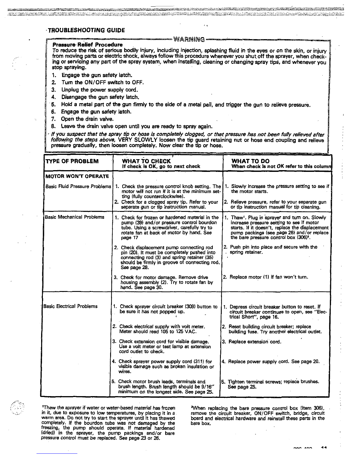
,TROUBLESHOOTING
GUIDE
~.
~~~~U~~
-
...
1.
Engage the gunsafetylatch.
2.
Turn
the
ONIOFF
switchto
OFF.
3.
Unplug
the
powersupplycord.
4.
Disengagethegunsafetylatch.
5.
Hold
a
metal
part
of
the
gun
firmly
to
the
side
of
a
metalpail, and trigger the
gun
to relievepressure.
6.
Engagethegunsafetylatch.
8.
Leave the drain
valve
openuntilyou
are
readytosprayagain.
BasicMechanicalProblems
1.
Check for fmzenor hadened material in the
1.
Thaw'.Plug in sprayerand turn on.Slowi)
pump
(39)
and/or pressurecontrolbourdonincreasepressure setting
to
see
if
motor
tube. Using
a
screwdriver, carefully try to
rotate fan
at
back
of
motor by hand. See
stam.
If
it
doesn't, replace the displacemei
page
77
the
barepressure controlbox
(306)'.
pump packings (see page
26)
andlor replac
2.
Checkdisplacement pumpconnecting rod
2.
Push
pin into placeandsecure with
the
connecting md
(3)
and spring retainer
135)
'
pin
1201.
It
must be completelypushed into
-
springretainer.
should
be
firmly
in
grmw
of
connecting rod.
See page
28.
3.
Cheok for motor damage. Remove driw
2.
Replace motor
(1)
if
fan
won't turn.
housing assembly
(2).
Try to rotate fan by
hand.
See
uaae
30.
lsicElectricalProblems
1.
Checksprayer circuitbreaker 1309'buttonto
1.
Depress circuit breaker buttonto reset. If
besure
it
has not poppedup. ciicuit breaker continuesto open,
see
"Elec
3
tricalShort",page
16.
2.
Checkelectricalsupply with volt meter.
2.
Reset
building circuit breaker;replace
Metershouldread
105
to
125
VAC. building
fuse.
Try
anotherelectricaloutlet.
3.
Checkextensioncord for visibledamage.
3.
Replaceaxtension cord.
Use
a
volt meter or test lamp
at
extension
cord outletto check.
4.
Ch,ecksprayerpower supplycord
(31
1)
for
4.
Replacepower supply cord.
See
page
20.
wlble damage such
as
broken insulation or
wires.
5.
Check motorbrush
leads,
terminalsand
5.
Tightenterminalscrews; replaw brushes.
brushlength.Brushlengthshouldbe
9/16"
See
page
25.
minimum onthe longest side.
Sea
page
25.
..:;
..
..
. . ..
,.
.
'~~
,.
'Thaw thesprayer
if
water orwater-basedmaterialhas frozen Wenreplacingthebare presure contml box litem
306).
."
in
it,
duetoexposure to low temperatures,byplacing
it
in
a
warm
area.
Do
not
try to start the sprayeruntil
it
has
thawed remove the circuit breaker,
ON/OFF
switch,bridge.circuit
board and electrical hardware and reinstall these parts in the
completely.
If
the bourdontubewas not damaged by the
freezing. thepumpshould operate. If materialhardened bare box.
pressure control must be replaced.
See
page
23
or
26.
(dried)
in
thesprayer, thepumppackings and/or bare
"
.^..
..
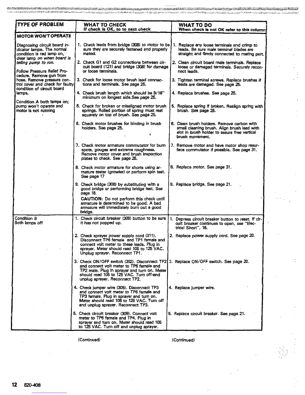
HOTOR
WONTOPERATE
Iiagnosingcircuit board
in-
Iicator lamps. The normal
andition is red lamp on,
$ear lamp
on
when
board
I
elling
pump
to
run.
:allow
Pressure Relief
Pro-
ndure. Remove gun from
lose. Remove pressure cor
rol
cover and check for fat
ondition
of
circuit board
mps.
:ondtion
A both lamps
On;
lump won't operate and
mor
is
not
running
Dndition
8
fh lamps
off
refer
to
*is colu~
sure they aresecurelyjastenedand properl)
mated.
1.
Checkleads from bridae
13081
to motor
to
be
1.
Replaceany
loose
terminals and crimp to
I
leads.Besuremaleterminalbladesare
straightand firmly connected to matingpa
2.
Check
G1
and
62
connections between cir-
or
loose
terminals.
cuit board
1121)
and bridge
1308)
for damagl
3.Check for loose motor brush lead wnnec-
tions
and terminals. See page
25.
4.
Check brush length which should
be
9/16"
minimum on longestside.Sea page
25.
5.
Check for broken or misaligned motor brush
squarely on top of brush. See page
25.
springs.
Rolled
portion
of
spring must
rest
6.
Check motor brush& for binding in brush
holders. See page
25.
I
7.
Check moior armature commutator for burn
spots, gouges and extreme roughness.
plates to check. See page
25.
Remove motor cover and brush inspenion
3.
Check motor armature for shorts using ar-
mature tester (growler) or perform spin test.
See page
17
good bridge or performing bridge
test.
See
page
18.
CAUTION:
Do
not
perform this check until
armature
is
determined to be good. A bad
armature will immediately bum out
a
good
bridge.
I.
Check circuit breaker
(309)
buttonto be sure
it
has not popped up.
3.
Check bridge
(308)
by substituting with
a
!.
ChecA sprayer power supply cord (31
1).
DisconnectTP6femaleandTP1femaleand
sprayer. Meter should read
105
to
125
VAC.
connect volt meterto these leads. Plug in
Unplugsprayer.Reconnect
TPl.
.
Check
ON/OFF
switch
13MI.
DisconnectTP2
~ ~~ ~
and connectvolt meter to TP6 female and
should read
105
to
125
VAC.Turin offand
TP2
male. Plug insprayer and turn on. Meter
,
~~~.
unplug sprayer. Reconnect TPZ.
.
Check jumper wire
1305).
DisconnectTP3
and connect volt meter to TP6 female and
TP3 female. Plug
In
sprayer and turn on.
and unplug sprayer. Reconnect TP3.
Meter should read
106
to
125
VAC. Turn
off
meter to TP6 female and TP4. Plug
in
Check circuit breaker
(309).
Connect volt
sprayer and turn on. Meter should read
105
to
125
VAC. Turn
off
andunoiuosoraver.
1
i
2.
Clean circuit boardmale terminals.Replacl
loose or damaged terminals. Securely reco
nect leads.
3. Tighten terminal
screws.
Replacebrushes
i
leads are damaged.
Sea
page
25.
4.
Replacebrushes.
Sea
page
25.
5.
Replace spring
if
broken. Realign spring
wi
brush. Seepage
25.
6.
Clean brush hoiders.Removecarbon
with
slot in brush holderto assure free vertical
SWall
cleaning brush..Alignbrush lead with
brush movement.
7.
Remove motor and have motor shop resur-
face commutator
if
possible. See page 31.
8.
Replace motor. Seepage31.
3.
Replacebridge.Seepage
21.
I.
Depress circuitbreaker bunon to reset.
If
cil
cuit breaker continuesto
open,
see
"Elec-
tricalShort",
16.
?.
Replace power supply cord.
See
page
20.
I.
Replace
ON/OFF
switch.
See
page
20.
..
..
Replace jumper wire.
.
Replace circuit breaker.
See
page
21.
Continued) (Continued)
.::
!
..
.. .
.,
..
:ontiition
B
Continued)
ondition
C
'nplug sprayed
ed
lamp
on,
clear lamp
oi
WHAT
TO
CHECK
If
check
is
OK,
go
to
next
check
6.
Check motor thermal cutout switch.
female. Plug in and turn
on
sprayer. Meter
Connect volt meter to TP6 female and
TP9
should read
105
to
125
VAC. Turn
off
and
unplugsprayer.
7.
Check microswitch
1301).
Reconnect
TP6
connectors. Connect volt meter to TP15
VAC.
male and TP4. Meter should read
50-125
8.
Visually inspect microswitch
1301)
button.
Adjustment stud
101
should
not
depress th
microswitchbunon when fluid pressure is
with small screwdriver; an audible click in-
zero.
Manually check by depressing button
dicates.micmswitch
is
in
normal position.
9.
Check microswitch
1301)
continuity with
oh
meter. Be
sure
sprayer
is
unplugged1
Mete!
should read zero ohmswith
no
fluid pressu
in the sprayer.
10.Check
all
terminals for damage or
loose
fit.
Reconnect
Tffi
connectors.
11.Check circuit board
l307)
by substituting
w'kh
a
good board.
See
page
22.
I.
Check circuit board
1121)
by removing from
box
without
disconnecting wires;
see
page
22
for removal procedure.
-
WARNING:
Removingthe circuit board
while
Su'll
wired over-rides the optical detec
tor which could
causa
the sprayer to ovar-
tion
properly. Turn the sprayer
on
ONLY
pressurize.
if
the microswitchdoes
not
func
long enough to check lamp condition, then
WARMING:
To reduce
the
risk of electric
shut
off
immediately.
shock, handle board by edges onbl
Do
not
with the board1
allow any metal objects to come in contact
Plug inand turn
on
sprayer. Clear lamp
should be
on
now
-
removing the circuit
off
and unplugsprayer.
board over-rides the optical detector.
Turn
.
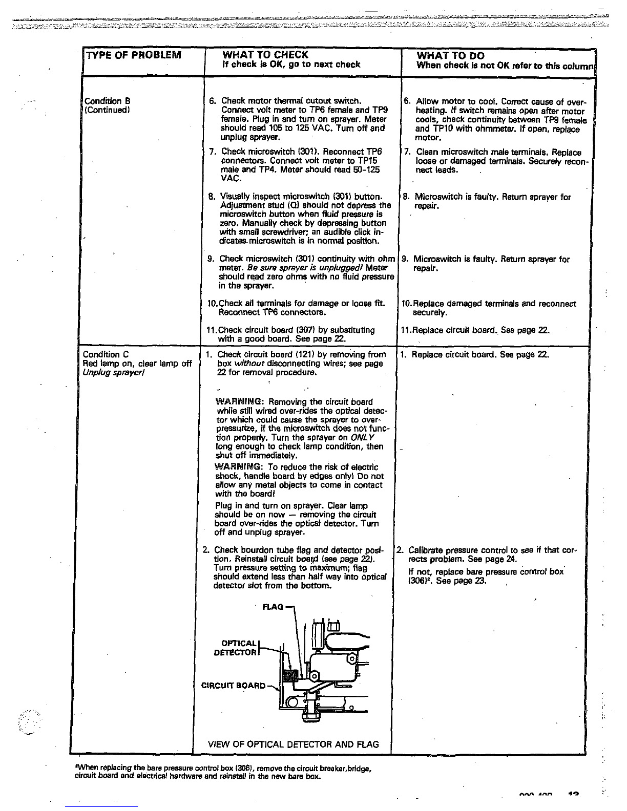
Check bourdon tube flag and detector posi-
tion. Reinstall circuit boar@ (see page
2).
Tum pressure
setting
to maximum; flag
detector slot from the bottom.
should extend
less
than half way into optical
DmCTOR
OPTICAL
IRCUIT
BOARD
VIEW
OF
OPTICAL DETECTOR AND
FLAG
When replacing
the
bare
pressure
control
box
13081.
remove
the
cirwtt
breaker,bridge.
circuit board and
electrical
hardware
and
reinstall
in
the
new
bare
box.
When
check
is
not
OK
refer
to
thk
colu
WHAT
TO
DO
6.
Allow
motor
to cool. Correct
cause
of ove
heating.
If
switch remains
open
after
motc
cools, check continuity
Ween
TW
fama
and
TPlO
with ohmmeter.
if
open, replacs
motor.
7.
Clean microswitchmaleterminals.Raolact
nect
leads.
loose or damaged terminals. Securely
rex
~~~-
~~
8.
Microswitch
is
faulty. Return sprayer for
repair.
3.
Microswitch
is
faulty.
Return
sprayerfor
remir.
I0.Replace damaged terminals and reconnect
I1.Replace circuitboard.
See
page
22.
securely.
.
Replace circuitboard.
See
page
22.
Calibrate pressurecontmlto
see
if
that cor-
rects
problem.
See
page
24.
(306)'.
see
page
23.
If not, replace bare pressure control box

WHAT
TO
CHECK
If
check is
OK.
go
to
next check
1.
Check for worn spray tip.
2.
to stroke
when
gun trigger is released. Plug
Check to
see
that
pump does not continue
inand turn onsprayer. Prime with material.
engage
safely
latch. Relieve pressure, turn
Trigger gun momentarily, then release
and
off
and unplug sprayer.
3.
Checkelectricalsupply with volt meter.
Meter should read 105
to
125VAC.
4.
Checkextensioncordsizeandlength;must
beet
least
12 gaugewire
and
no
longer thal
150
ft
(15.2.
m).
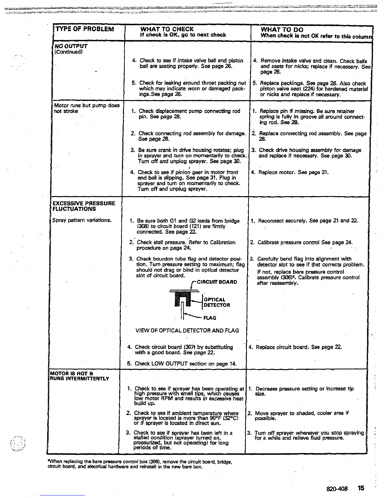
i.
Check
G1
and
62
leads
from bridge
(p81
to
circuit board
(3071
for damage or
loose
wire!
or connectors. Refer
to
page
22.
Procedure on page 24.
3.
Check
stall
pressure.Refer to Calibration
7.
Checkbridge
(3081.
+
and
-
leadsand ter-
and terminalsfor signs of overheating.
See
minals
to
motor. Inspect wiring insulation
page
18.
I.
Check for loose motor brush leads and ter-
minals.
See
page
25.
I.
Check for worn motor brushes which should
be 9/16 minimum length on longestside.
See
page
25.
0.Check for broken and misaligned motor
brush springs. Rolled portion of spring must
resf
squarely on top of brush.
1.Check motor brushes for binding
i:.
orush
holders. See page
25.
2.Check circuit board
(307)
by substituting
with
a
good circuit board.
See
page
22.
3.Check
motor
armature for shorts by.using an
armature tester (growler)or perform spin
test.
See
page
18.
3
4.Check bridge
(308)
by substituting with
a
test.
See
page
18.
good bridge or by performingthe bridge
CAUTION:
Do
not perform
this
check until
armature
is
determined
to
be good.
A
bad
armature will immediately bum
out
a
gcd
bridge.
Check material supply.
Check for clogged intake strainer.
See
page
26.
Check for loose suction tubeor fittings.
Sea
Page
26.
WHAT
ro
DO
When check
Is
not
OK
refer
to
this
colul
1.
FollowPressureReliefProcedurethen
replace tip.
See
your separate gun or tip
manual.
2.
Service pump. See page
26.
3.
Reset buildingcircuit breaker;replace
buildingfuse. Repair electrical outlet
01
another outlet.
1.
Replacewith
a
correct, grounded extension
cord.
i.
Clean circuit
board
mete terminals. Replace
lease
or defective lead terminals. Securely
reconnect
lead
terminals to board.
i.
Calibratepressure control.
See
page
24.
'.
Be sure male terminal blades are centered
and firmly connected to female terminals.
ing. Securely reconnect wires to bridge.
Replace any loose terminal or damaged wir-
i.
Tightenterminalscrews.Replacebrushes
if
.
Replacebrushes.Seepage
25.
leads are damaged. See page
25.
0.Replace spring if broken. Realign spring witt
brush.
See
page
25.
1.Clean brushholders. remove carbon
dust
with
slot
in brush holder to assure
free
ver-
with small cleaning brush. Align brush lead
tical
brushmovement.
Z.Repiace circuit board.
See
page
22.
Meplacemotor.
See
page
31.
1.Repiace bridge.
See
page 21.
Refill
and reprime pump.
Remove and clean, then reinstall.
Tighten;
use
thread sealant or sealing tape
on threads
if
necessary.
(Continuedl [Continued)
.-
-
.
.
..
YO
OUTPUT
Continued)
dotor
mns
but pump doe
ot stroke
KCESSIVE
PRESSURE
IUCTUATIONS
,ray pattern variations.
ITOR
IS
HOT
e
NS
INTERMlllENTLY
WHAT TO
CHECK
If
check is
OK,
IIO
to
next
check
4.
Check to
see
if
intakevalve
ball
and piston
ball are seating properly.
See
page
26.
5.
Check for leaking around throatpacking
nt
which may indicate worn or damaged pack
ings.See page
26.
1.
Checkdisplacementpumpconnecting rod
pin.
See
page
28.
2.
Check connecting rod assemblyfor damage
3.
Be
SUA
mnk
in drive housing rotates; piu(
in sprayer and turn
on
momentarilyto chec
Turn
off
and unplugsprayer.
See
page
30.
see
page
m.
I
4.
Check to
see
if
piniongear inmotor front
sprayer and turn
on
momentarilyto check.
end bell
is
slipping.
See
page
31.
Plug in
Turn
off
and unplugsprayer.
1.
Besure both G1 and
G2
leads from bridge
(306)
to circuit board
(121)
are firmly
connected.
See
page
22.
2.-
Check stallpresure.'kefer to Calibration
procedure
on
page
24.
3.
Check bourdon tube flag and detector posi-
tion. Turn pressure setting
to
maximum;
fla!
should not drag or bind in optical detector
slot of circuit board.
rClRCUlTBOAR0
VIEW
OF
OPTICAL DETECTOR AND FLAG
4.
Check circuit board
1307)
bysubstituting
with
a
good board.
Sea
page
22.
5.
Check
LOW
OUTPUT section
on
page
14.
1.
Check to
see
if
sprayerhas bean
o
erating
a
high pressurewith small tips, whicR
muses
low motor RPM and results in excessive hear
buildup.
2.
Check to see if ambient temperature where
sprayer
is
locatedis more than90°F
(32W
or
if
sprayer is located
in
direct
sun.
3.
Check to
see
if
sprayer has been
left
in
a
stalled
condition (sprayerturned
on,
perlods of hme.
preqrized butnot operating)for long
"
It
!
"
3.
:
k.
4
"
1
2
3
3.
4.
"
t
1.
2.
3.
WHAT
TO
DO
When check
is
not
OK
refer
to
this
COIU
4.
Removeintake valveand clean.Check bal
and seats for nicks; replace
if
neceaary.
.$
5.
Replace packings.
See
page
26.
Also
chec
pistonvalve
seat
(224)
for hardened mater1
or nicks and replace
if
necessary.
.page
26.
I.
ReolaceDin
if
rnissino.Besureretainer
spring is7fullyin groob
all
around connect
ing rod. See
28.
~ ~ ~~~ ~
i.
Replaceconnecting rodassembly.
See
pag
I.
Check drive housingassembly for damage
andreplace
if
necwry. Seepage
30.
m.
..
Replace motor.
See
page
31.
.
Reconnect
securely.
See
page
21
and
22.
.
Calibrate pressure control
See
page
24.
,
Carefully bend flag into alignment with
detector slot
to
see
if
that corrects problem
assembly
(306)'.
Calibrate pressure control
If
not, replace barepressure control
after reassembly.
Replacecircuit board.
See
page
22.
SUE.
Decrease pressure setting or increasetip
Move sprayer
to
shaded, cooler area
if
possible.
Turn
off
sprayer whenever
you
stop spraying
for
a
while and relieve fluid pressure.
Whenreplacing
the
bare
pmure
conuol
box
1306).
rarnove
the
circuit board, bridge,
urcuitboard, and siecuical hardware and
reinstall
in
the
new bare
box.

as
won
as
sprayer swfich
IS
Building circuit bkake!
opens
turned
on.
CAUTION
Any
short in any part
of
tk
motorpowercircuit,which
mnnected
to the output sid
Ji
the
bridge,
will
muse
tb
]ridge to bum out immediatt
repair ail shorts before checl
y.
Correctlydiagnosean
ng and replacing bridgf
Wilding circuit breaker opens
is
soon
as sprayer
is
plugged
nto
outlet
and sprayer
is
NO:
umed
on.
iprayer circuit breaker
opens
fter sprayer operates for
onl)
.to
10
minutes.
1.
Check
all
electrical wiring for damaged in-
sulation, and
ail
terminals for
loose
fit
or
damage. Be sure to check
wires
between
pressure controland motor whichare
enca
ed
in conduit
(22).
See
page
30.
2.
Check for missing inspection plate gasket
(sea
page
251,
bent terminal forks
or
other
cause
a
short.
metal
to
meta.wntact
points which could
I
13.
Check motor armature for shorts by using
i
armature tester (growler)or perform spin
test.
See
page
17.
Inspect
windlngs for
burns.
~
4.
Check bridge
1308)
by substituting with
a
good bridge or
by
peiiormingbridge
test.
See
page
18.
CAUTION:
Do
not perform thischyk unti
armature is determine&to be good. A bad
armature will immediate@ burn out
a
good
bridge.
1.
Check'BasicElectricalProblems'
on
Page
1
2.
Check ONlOFFswitch
(302)
See
page
20.
'Be
sue
the sprayer
is
unpiuggedlDisconnet
wires from switch and check switch
with
ohm meter.
The
ohm meter should read in-
with
the
switch
ON.
finity with the ON/OFF switch
OFF,
and Zen
CAUTION:
A
short in themotor circuit
wi
bum
the
bridgeout immediately, which infur!
closed mode.
usuallycauses
the
ON/OFFswitchtofaii.inth
1.
Check electrical supply with volt meter.
Meter shouldread
105
to
125
VAC.
2.
Check tightnessof pump packing 'nut. Over-
tightening nut tightens packings on rod,
packings:
See
page
26.
restricts
pump action, and damages
3.
Check
stall
pressure.Remove
the
elbow
(€3)
and secondan/ ball valve
(301
from
the
tee
5ooD
psi
(350
bar) fluid-filledpressure gauge
(124)
at the pressure
control
outlet.
Install
a
turn
on
sprayer. Slowly increaseprasslre
in the
tee
(124).
See
page
24.
Plug
in
and
28M)3wo
psi
US210
bar). Turn
off
and
setting
to
maximum. Pump should
stall
at
unplugsprayer.
1.
After determining that there
is
no
short in
system,
reset
circuit breaker bunon.
I
1.
Repair or replace any damaged wiring or ter-
minals. Securely reconnect
all
wires.
2.
Correct faulty conditions.
3.
Replacemotor.
See
page
31.
4.
Replacebridge.
See
page
21.
2.
Replace ON/OFF switch.
See
page20.
1.
if voltage is
too
high,do not operate spraye
untilcorrected.
2.
Loosen
packingnut.Check for leaking
around throat. Replace pump packings.
if
necessaty.
See
page
26.
Calibrate pressure control.
See
page
24.
1.
If
circuit breaker continues
to
open (bunon
pops up), replace the circuit breaker.
See
page
21.
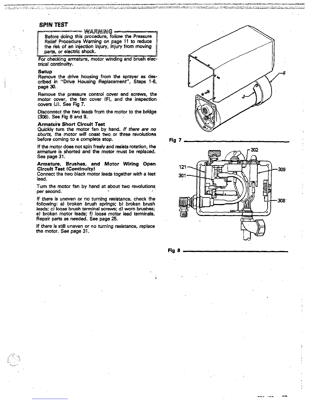
SPIN
TEST
..
.
..
..
trial
continuity.
For checking armature, motor winding and brush
elec-
setup
Remove the drive housing from the sprayerasdes-
page
30.
Remove thepressure control coverandscrews, the
motor cover, thefan cover(Fl,and theinspection
covers
(Jl.
SeeFig
7.
Disconnect the
two
leads from the motorto the bridge
(5081.
SeeFig
8
and
9.
Armatu'ie Short CircuitTest
shorts,
the motor will coast two.or three revolutions
Quickly turn
the
motor fan by hand.
If
there
are
no
before comingto a complete stop.
armature
is
shorted and the motor must bereplaced.
If
the motor doesnotspin freeiy and resists rotation, the
See
page
31.
Armature, Brushes, andMotorWiring Open
Connect the
two
black motorleads togetherwith a
test
Circuit Test (Continuity)
lead.
Turn
the motor
fan
by hand
at
about
two
revolutions,
per second.
If
there
is
uneven or no turning resistance,check the
following:
a)
brokenbrush springs; b) brokenbrush
el broken motor leads; fl
loose
motor leadterminals.
leads: c) loosebrush terminal
screws;
d)
worn brushes;
Repair parts
as
needed. See page
25.
If
there
is
still
unevenor no turning resistance, replace
the motor.
See
page
31.
j
cribed
in
"DriveHousingReplacement",Steps
1-6,
Fig
7
Fig
8
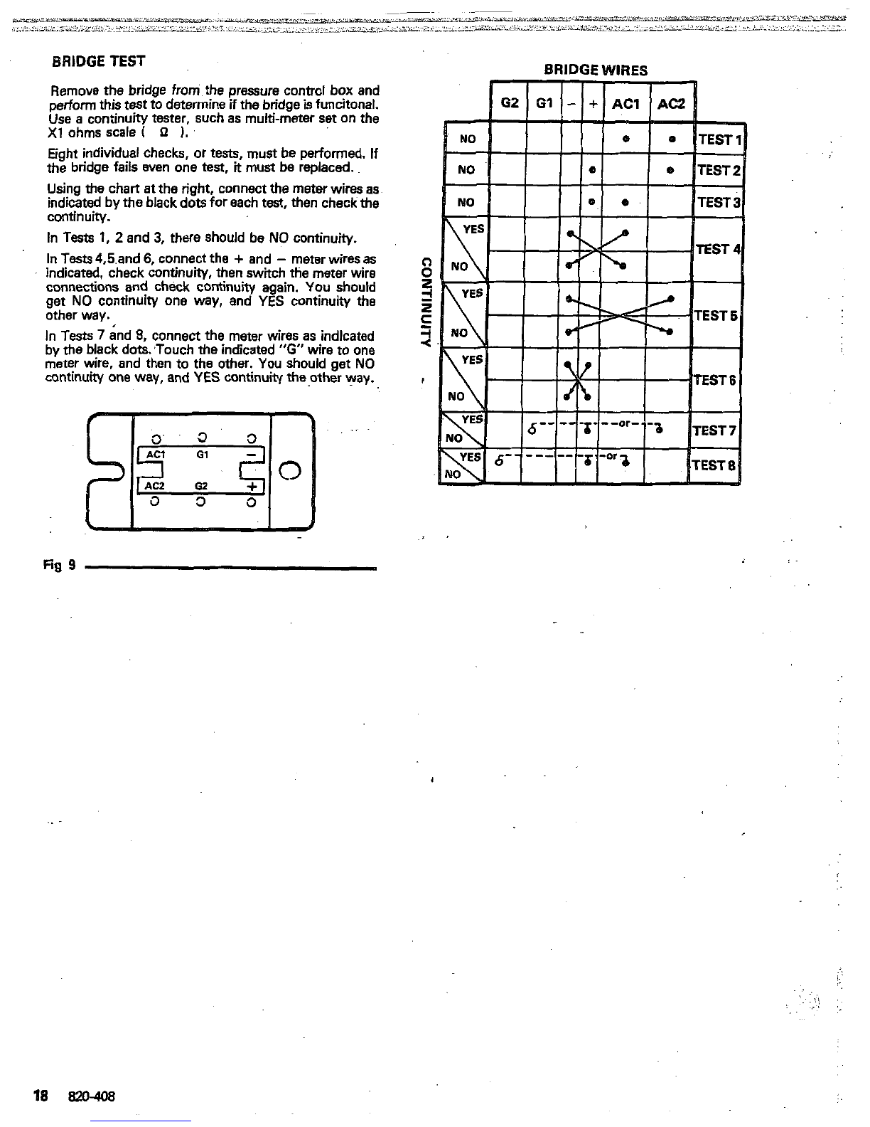
BRIDGE
TEST
performthis
test
to
determine
H
the bridgeisfuncitonal.
Remove
the
bridge from.the pressure control box and
X1
ohmsscale
(
0
1.
Use
a
continuity tester, such as multi-meterset on the
Eight individualchecks,
or
tests, mustbe performed. If
the bridge fails even one test,
it
must be replaced.
Using thechart
at
the right, connect the meter wiresas
indicatedbythe blackdotsfor each
test,
then check
the
continuity.
In
Tests
1,
2
and
3,
there should be
NO
continuity.
In
Tests
4,5.and
6,
connect the
+
and
-
meter
wires
as
indicated, check continuity, thenswitch the meter wire
connectionsandcheckcontinuityagain.
You
should
get
NO
continuity oneway,and
YES
continuity the
other way.
In
Tests
7
and
8,
connect
the
meter wires as indlcated
by the blackdots:Touch the indicated
"G"
wire toone
meter wire, and then
to
the other.
You
should get
NO
continuity one way, and
YES
continuity
the
other way.
Fig
9

......
..
..
....
.-
'
.
.:
Procedure Page
General RepairNotes
.........................................
19
ONIOFF S~tch
PowerSupplyCord
20
................................................
Circuit Breaker
.................................................
21
CircuitBoard
22
BridgeRectifier
21
Calibration
24
Pressure Control
23
Motor Brush
....................................................
25
Displacement Pump
...........................................
26
Bearing Housing
Et
Connecting Rod
......................
28
Drive Housing
..................................................
30
Motor
.............................................................
31
Parts Drawing
&
List, UltimateNovam
1000
............
32
Parts Drawing
8
List, PressureControl
...................
34
P,arts Drawing
&
List,
Displacement Pump
..............
36
...........................................
.................................................
....................................................
...............................................
.......................................................
The following tools are needed when repairingthis
sprayer.
Phillipsscrewdriier
Small flatblade screwdriver
Needle nose pliers
Adjustable wrench
Plastic mallet
2"
adjustable, open-end wrench
Torque wrench
114"
hex key wrench
3/16"
hex key wrench
518"
socket wrench
318"
open end wrench
112"
open end.wrench
314"
open end .'wrench
718"
open end wrench
Bearing grease
High quality motoroil
For
cafibration
procedure
only:
318"
ignitionwrench
0.015"
spray tip
5
gallon pail
High pressure, oil-filled
test
gauge,
Part
No.
820-455
Clean water
NEW
3000
p
7
bar)highpressuresprayhose
Mineral spirit!
GENERAL
REPAlR
MOTES
Before repairing any partofthesprayer, read thefollow-
ing generalrepairnotesandtherepairprocedure. Be
sure you have the necessary tools and parts available.
1.
When disconnectingwires in the pressure control
assembly, use needle nose plierstoseparate mating
connectors.
When reconnecting the wires, be sure theflatblade
wrap-around blade of the female connector when
of the insulated male connector is centered in the
the connection ismade.
tion,
.be
sure
to
properlymateconnectors,
and
wire couldloosen the connectorfrom the wire.
never
pull on
a
wire
to
disconnect
it.
Pulling on
a
2.
Route wires in the pressure control assembly
carefully through the legs of the U-shaped bourdon
tube,whereappropriate,
to
avoid interfering with
the bourdontube which moves asthe pressure
set-
ting changes and to avoid pinching thewires bet-
ween the pressure control box and cover.
CAUTION
performance or damageto the pressure control.
Improper wire routing can result in poor sprayer
3.
Keep
all
screws,nuts,washers,gaskets,andelec-
trical fittings removed during repairprocedures.
These partsare notnormally providedwith replace-
ment assemblies.
4.
Testyourrepairbeforeregularoperation
of
.the
sprayer
to
besuretheproblem
is
corrected.
..
repair procedure againtoverify that everythingwas
If
thesprayer doesnotoperate properly, review the
done correctly. If necessary, refer
to
the
TroubleshootingGuide
to
help identifyother possi-
ble' problems and solutions.
includingelectric
ingparts or elec-
or
a
tool while
inspecting therepair.
Shut
off
the sprayer andunplug
it
as soon
as
you
complete the inspection.
before operating the sprayer.
Reinstall
all
covers, gaskets, screws and
CAUTION
-.
Do-not runthesprayer dry for..more !han
30
seconds to avoid damaging the pump packings.
5.
Reinstallthe motor cover.beforeregular operation
:
of the sprayer and replace
it
if
it
is damaged.
The
cover directs cooling air around the motor to help
prevent overheating.
It
can also help prevent bums,
fire or explosion; see
the
WARNING, below.
..
820-408
19
':
,.
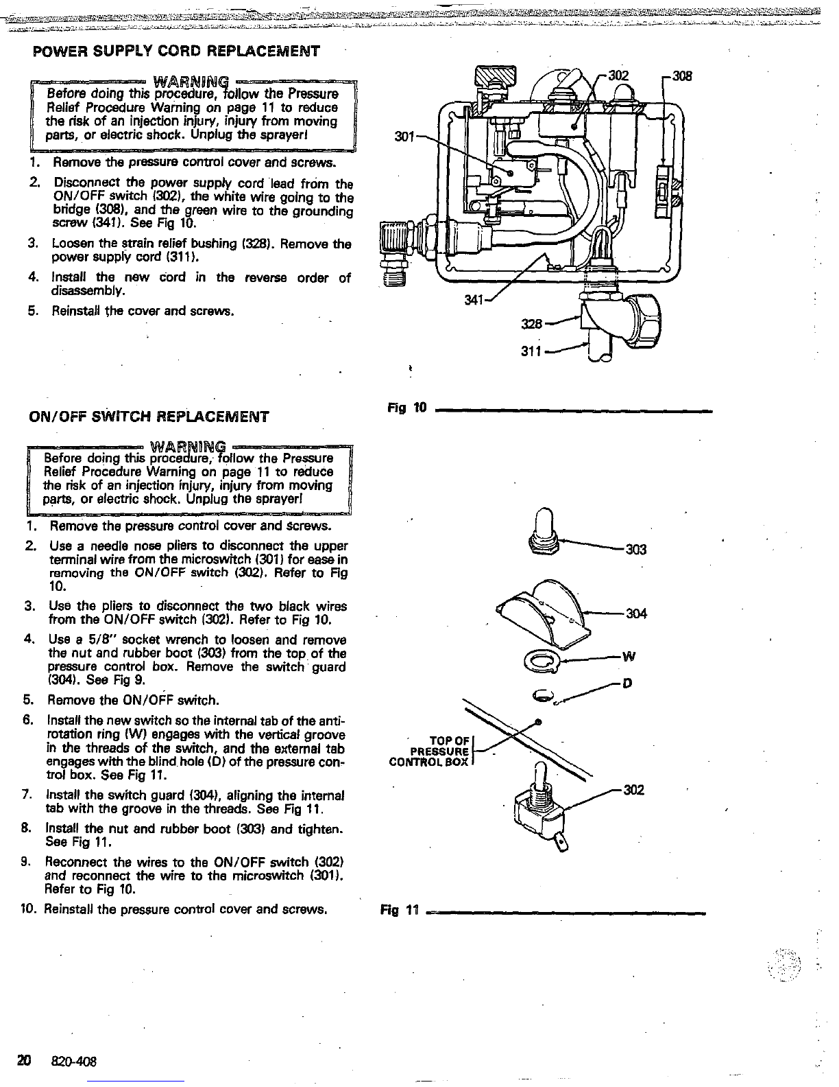
POWER SUPPLY CORD REPLACEMENT
1.
Removethe pressure controlcover andscrews.
2.
Disconnect
the
powersupply cord lead from the
ON/OFF switch
/XU).
the white
wire
ooino
to
the
bridge
(W),
and the.green
wire
to~the
grounding
"
screw
(341).
see
Fig
10.
3.
Loosen thestrainreliefbushing
1328).
Remove
the
4.
Install the new cord in thereverseorder of
5.
Reinstallthecover
and
screws.
power supply cord
(311).
disassembly.
QNIQFF
SWITCH REPLACEMENT
Fig
10
1.
Remove
the
Dressure control coverandscrews.
n
2.
3.
4.
5.
6.
7.
8.
9.
10.
Use
a needlenosepliers to disconnecttheupper
terminal wirefrom
the
microswitch
(301)
for
ease
in
removingthe ONlOFF switch
~302).
Refer to Fig
10.
from
the
ON/OFF switch
1302).
Refer to Fig
10.
Use
the pliers to disconnectthe
two
blackwires
the nut and rubber boot
13G3)
from the toD of
the
Use
a
5/8"
socketwrench to loosen
and
remove
pressure control box.Remove the switch
'
guard
(3041.
SeeFig
9.
Remove the ON/OFF switch.
Installthe new switch
so
the internal tab
of
the
anti-
in
the
threads
of
the switch, and the external tab
rotation ring
(W)
engages with the vertical groove
engageswith
the
blindhole
(D)
of
the pressurecon-
CONTROL
BOX
trot box.
See
Fig
11.
Installthe switch guard
(304).
aligningtheinternal
302
tab
with the groove in the threads.
See
Fig
11.
Install the nut andrubber boot
(303)
and tighten.
See
Fig
11.
andreconnectthewire to the microswitch
(301).
Reconnectthewires to theON/OFF switch
(302)
Refer to Fig
10.
Reinstallthe pressure control coverandscrews. Fig
1'1
-.
:.
..
ij
...,.
.
,...
:.:.:
.
,
.
. .
.
..
.:
'
..
.:
This manual suits for next models
1
Other Sherwin-Williams Paint Sprayer manuals

Sherwin-Williams
Sherwin-Williams 820-206 User manual

Sherwin-Williams
Sherwin-Williams NOVAspx 824-012 User manual

Sherwin-Williams
Sherwin-Williams ULTIMATE Plus+ 1000 User manual

Sherwin-Williams
Sherwin-Williams 820-169 Series B User manual

Sherwin-Williams
Sherwin-Williams PT2500 User manual

Sherwin-Williams
Sherwin-Williams ULTIMATE 824-030 User manual

Sherwin-Williams
Sherwin-Williams SUPERNOVA 820-002 User manual

Sherwin-Williams
Sherwin-Williams ProComp 3800 User manual

Sherwin-Williams
Sherwin-Williams 820169 D Series User manual

Sherwin-Williams
Sherwin-Williams 820-001 User manual


