Sherwin-Williams SUPERNOVA 820-002 User manual

OWNER’S MANUAL
820–008 Rev. M
SUPERSEDES
Rev
. L
1/2 gpm, Portable, Electric SUPERNOVAAIRLESS
P
AINT SPRAYER
PATENT
NO. 4,323,741
Model 820–002, Series F
Without
hose, gun, or filter
2750 psi (190 bar) MAXIMUM WORKING PRESSURE
INDEX
Warnings 2.
. . . . . . . . . . . . . . . . . . . . . . . .
Avertissement 4
. . . . . . . . . . . . . . . . . . . .
Advertencia 6
. . . . . . . . . . . . . . . . . . . . . . .
Setup 8
. . . . . . . . . . . . . . . . . . . . . . . . . . . .
Flushing
Guidelines
9.
. . . . . . . . . . . . . . .
Adjust
the Spray Pattern
10.
. . . . . . . . . .
Application
Methods
10.
. . . . . . . . . . . . .
Shutdown
and Care
11.
. . . . . . . . . . . . .
Troubleshooting
Guide
12.
. . . . . . . . . . .
Service 14–19
. . . . . . . . . . . . . . . . . . . . . .
Displacement
Pump
14.
. . . . . . . . . . .
Connecting
Rod & Bearing
16.
. . . . . .
Drive Assembly 16.
. . . . . . . . . . . . . . .
Capacitor 17
. . . . . . . . . . . . . . . . . . . . . .
Motor 17
. . . . . . . . . . . . . . . . . . . . . . . . .
Pressure
Control & Circuit Board.
18.
Calibrating
the Pressure Control
19.
.
Parts Drawing & Lists 20.
. . . . . . . . . . . .
Accessories 23
. . . . . . . . . . . . . . . . . . . . .
Technical
Data
Back Cover.
. . . . . . . . . .
Warranty Back Cover.
. . . . . . . . . . . . . . .
The
SHER
WIN–WILLIAMS COMP
ANY
, CLEVELAND, OHIO 441
15
This
manual contains Important
W
arnings and Instructions. Read the
manual and keep it for reference.
Liquids
can be injected into the body by high
pressure airless spray
or
leaks – especially hose leaks.
Keep
body clear of the nozzle. Never stop leaks with any part of the
body.
Drain all pressure before removing parts.A
void accidental trig
-
gering
of gun by always setting safety latch when not spraying.
Never spray without a tip guard.
In case of accidental skin injection, seek immediate
“Surgical
T
reatment”.
Failure to follow this warning can result in amputation or serious
injury.
FIRE
AND
EXPLOSION HAZARD
SKIN INJECTION
HAZARD
READ AND UNDERSTAND ALL LABELS AND INSTRUCTION MANUALS BEFORE USE
Spray
painting,
flushing or cleaning equipment with flammable liq
-
uids
in confined areas can result in fire or explosion.
Use
outdoors or in extremely well ventilated areas. Ground equip
-
ment,
hoses, containers and objects being sprayed.
Avoid
all ignition sources such as
static electricity from plastic drop
cloths,
open flames
such as pilot lights, hot objects such as ciga
-
rettes,
arcs from
connecting or disconnecting power cords or turn
-
ing
light switches on and off.
Failure
to follow this warning can result in death or serious injury
.
NOTE: This
is an example of the DANGER label on your sprayer
.
This label is available in other languages, free of charge.
See page 23 to order
.
SAFETY
W
ARNINGS
HIGH PRESSURE SPRAY CAN CAUSE SERIOUS INJURY.
FOR PROFESSIONAL USE ONLY. OBSERVE ALL WARNINGS.
Read and understand all instruction manuals before operating the equipment.
FLUID INJECTION HAZARD
General
Safety
This
equipment generates very high fluid pressure. Spray from
the gun, leaks or ruptured components can inject fluid through
your
skin and into your body
,
and cause extremely serious bodily
injury, including the need for amputation. Also, fluid injected or
splashed
into the eyes or on the skin can cause serious damage.
NEVER
point the spray gun at any one or at any part of the
body
.
NEVER
put your hand or fingers over the spray tip. NEVER try
to “blow back” paint; this is NOT an air spray system.
ALWAYS have the tip guard in place on the spray gun when
spraying.
ALWAYS
follow the
PRESSURE RELIEF PROCEDURE
, below
,
before
cleaning or removing the spray tip or servicing any sys
-
tem equipment.
NEVER try to stop or deflect leaks with your hand or body
.
Be
sure equipment safety devices are operating properly before
each
use.
Medical
Alert––Airless Spray W
ounds
If any fluid appears to penetrate your skin, get EMERGENCY
MEDICAL CARE AT ONCE. DO NOT TREAT AS A SIMPLE
CUT.
T
ell the doctor exactly what fluid was injected.
Note
to Physician
:
Injection in the skin is a
traumatic injury
. It
is important to treat the injury surgically as soon as possible.
Do not delay treatment to research toxicity. Toxicity is a
concern with some exotic coatings injected directly into the
blood
stream. Consultation with a plastic surgeon or reconstru
-
ctive
hand surgeon may be advisable
.
Spray
Gun Safety Devices
Be sure all gun safety devices are operating properly before
each
use. Do not remove or modify any part of the gun; this can
cause
a malfunction and result in serious bodily injury
.
Safety
Latch
Whenever
you stop spraying, even for a moment, always set the
gun
safety latch in the closed or “safe” position, making the gun
inoperative.
Failure to set the safety latch can
result in accidental
triggering
of the gun.
Diffuser
The
gun dif
fuser breaks up spray and reduces the risk of fluid in
-
jection when the tip is not installed. Check diffuser operation
regularly. Follow the PRESSURE RELIEF PROCEDURE, be-
low,
then remove
the spray tip. Aim the gun into a metal pail, hold
-
ing
the gun firmly to the pail. Using the lowest possible
pressure,
trigger
the gun. If the fluid emitted
is not
dif
fused into an irregular
stream,
replace the dif
fuser immediately
.
Tip
Guard
ALWAYS have the tip guard in place on the spray gun while
spraying. The tip guard alerts you to the fluid injection hazard
and
helps reduce, but does not
prevent, the risk of accidentally
placing
your fingers or
any part of your body close to the spray
tip.
Trigger
Guard
Always
have the trigger guard in place on the gun when spraying
to reduce the risk of accidentally triggering the
gun if it is dropped
or
bumped.
Spray T
ip Safety
Use
extreme caution when cleaning or
changing spray tips. If the
spray
tip clogs while spraying, engage the gun safety latch im
-
mediately. ALWAYS follow the PRESSURE RELIEF PROCE-
DURE,
below, and then remove the spray tip to clean it.
NEVER
wipe of
f build–up around the spray tip until the pressure
is
fully relieves and the gun safety is engaged.
PRESSURE RELIEF PROCEDURE
To
reduce the risk
of serious bodily injury
, including fluid injection,
splashing
fluid or solvent in the eyes or on the skin, or injury from
moving parts or electric shock, always follow this procedure
whenever
you shut of
f the sprayer
, when checking or servicing
any
part of the spray system, when installing, cleaning or chang
-
ing
spray tips, and whenever you stop spraying.
1.
Engage the gun safety latch.
2.
Turn the ON/OFF switch to OFF.
3.
Unplug the power supply cord.
4. Disengage
the gun safety latch. Hold a metal part of the
gun
firmly
to the side of a grounded metal pail, and trigger the gun
to
relieve pressure.
5. Engage the gun safety latch.
6. Open the pressure drain valve, having a container ready to
catch
the drainage. Leave the valve
open until you are ready
to
spray again.
If
you suspect that the spray tip or hose is completely clogged,
or that pressure has not been fully relieved after following the
steps
above,
VER
Y SLOWL
Y loosen the tip guard retaining nut
or
hose end coupling to relieve pressure gradually
, then
loosen
completely.
Now clear the tip or hose.
1,5 2 3 4 6 0739

3
MOVING
P
ARTS HAZARD
Moving
parts can pinch or amputate your fingers or other body
parts.
KEEP CLEAR of moving parts when starting or operating
the
sprayer
. Follow the
Pressure Relief Procedure
on page 2
before
checking or servicing any part of the sprayer
, to prevent
it
from starting accidentally
.
EQUIPMENT MISUSE HAZARD
General
Safety
Any misuse of the spray equipment or accessories, such as
overpressurizing, modifying parts, using incompatible chemi-
cals
and fluids, or using worn or damaged parts, can cause them
to
rupture and result in fluid injection, splashing in the eyes or on
the
skin, or other serious bodily injury
,
or fire, explosion or prop
-
erty
damage.
NEVER
alter or modify any part of this equipment; doing so could
cause
it to malfunction.
CHECK
all spray equipment regularly
and repair or replace worn
or
damaged parts immediately
.
Always
wear protective eyewear
, gloves, clothing and respirator
as
recommended by the fluid and solvent manufacturer
.
System
Pressure
This
sprayer can develop 2750 psi (190 bar)
MAXIMUM WORK
-
ING
PRESSURE.
Be sure all spray
equipment and accessories
used
are rated to withstand the this pressure. DO NOT exceed
the
maximum working pressure of any component or
accessory
used
in the system.
Fluid and Solvent Compatibility
All
chemicals used
in the sprayer must be chemically compatible
with
the wetted parts
shown in the
TECHNICAL DA
TA
on page
24.
Consult your chemical supplier to ensure compatibility
.
Do
not use 1,1,1-trichloroethane, methylene chloride, other ha
-
logenated hydrocarbon solvents or fluids containing such sol-
vents in this equipment, which contains aluminum and/or zinc
parts.
Such use could result in a serious chemical reaction, with
the possibility of explosion, which could cause death, serious
bodily
injury and/or substantial property damage.
HOSE SAFETY
High pressure fluid in the hoses can be very dangerous. If the
hose develops a leak, split or rupture due to any kind of wear,
damage
or misuse, the high pressure spray emitted
from it can
cause
a fluid injection injury or other serious bodily injury or
prop
-
erty
damage.
ALL
FLUID HOSES MUST HA
VE STRAIN
RELIEFS ON BOTH
ENDS!
The strain reliefs help protect the hose from
kinks or bends
at
or close to the coupling which can result in hose rupture.
TIGHTEN all fluid connections securely before each use. High
pressure
fluid can dislodge a loose coupling or allow high pres
-
sure
spray to be emitted from the coupling.
NEVER
use a damaged hose. Before each use, check the entire
hose for cuts, leaks, abrasion, bulging cover, or damage or
movement
of the hose
couplings. If any of these conditions exist,
replace
the hose immediately
. DO NOT try to recouple high pres
-
sure hose or mend it with tape or any other device. A repaired
hose
cannot contain the high pressure fluid.
HANDLE AND ROUTE HOSES CAREFULLY. Do not pull on
hoses to move equipment. Keep hoses clear of moving parts
and
hot surfaces of the pump and gas engine. Do not use fluids
or solvents which are not compatible with the inner tube and
cover of the hose. DO NOT expose Graco hoses to tempera-
tures
above 180
_
F (82
_
C) or below –40
_
F (–40
_C).
Hose Grounding Continuity
Proper hose grounding continuity is essential to maintaining a
grounded
spray system. Check the electrical resistance of your
fluid hoses at least once a week. If your hose does not have a
tag
on it which specifies the maximum electrical resistance, con
-
tact the hose supplier or manufacturer for the maximum resis-
tance
limits. Use a resistance meter in the
appropriate range for
your hose to check the resistance. If the resistance exceeds the
recommended
limits, replace
it immediately
. An ungrounded or
poorly grounded hose can make your system hazardous. Also
read
FIRE OR EXPLOSION HAZARD, below.
FIRE OR EXPLOSION HAZARD
Static
electricity is created by the flow of fluid through the
pump
and hose. If every part of the spray equipment is not properly
grounded,
sparking may
occur
, and the system may become haz
-
ardous.
Sparking may also occur when plugging in or
unplugging
a
power supply cord or using a gasoline engine. Sparks can ignite
fumes
from solvents and the fluid being sprayed, dust particles
and other flammable substances, whether you are
spraying
in
-
doors
or outdoors, and can cause a
fire or explosion and serious
bodily
injury and property damage.
If
you experience any static sparking or even a slight shock while
using this equipment,
ST
OP SPRA
YING
IMMEDIA
TELY.
Check
the entire system for proper grounding. Do not use the system
again
until the problem has been identified and corrected.
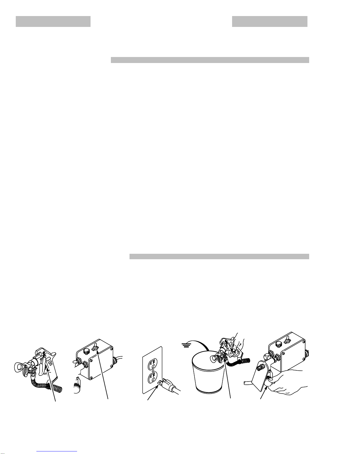
Grounding
To
reduce the risk of static sparking, ground the sprayer and all
other spray equipment used or located in the spray area.
CHECK
your local electrical code for detailed grounding
instruc
-
tions
for your area and type of equipment. BE SURE to
ground
all
of this spray equipment:
1.
Sprayer:
plug
the power supply cord, or
extension cord, each
equipped
with an undamaged
three-prong plug, into a proper
-
ly grounded outlet. Do not use an adapater. All extensions
cords
must have three wires and be rated for 15 amps.
2.
Fluid
hoses:
use only grounded hoses with a maximum
f 500
ft (150 m) combined hose length to ensure grounding continu
-
ity.
See
Hose Grounding Continuity above.
3.
Spray
gun:
obtain grounding through connection to a properly
grounded
fluid hose and sprayer
.
4.
Object being sprayed:
according to local code.
5.
Fluid supply container:
according to local code.
6.
All
solvent pails used when flushing,
according
to local code.
Use
only metal pails, which are conductive. Do not place the
pail on a non–conductive surface, such as paper or card-
board,
which interrupts the grounding continuity
.
7.
To maintain grounding continuity when flushing or relieving
pressure
,
always hold a metal part of the gun firmly to the side
of
a grounded metal pail, then trigger the gun.
Flushing
Safety
Reduce
the risk of fluid injection injury
, static
sparking, or splash
-
ing by following the flushing procedure given on page 9 of this
manual. Follow the PRESSURE RELIEF PROCEDURE on
page
2, and remove the spray tip before flushing. Hold a
metal
part
of the gun firmly to the side of a grounded metal pail and use
the
lowest possible fluid pressure during flushing.
IMPORTANT
United
States Government
safety standards have been adopted under the Occupational Safety and Health Act. These standards –
particularly
the General Standards, Part 1910, and the Construction Standards, Part 1926 – should be consulted.

4
AVERTISSEMENT
La
pulvérisation à haute pression peut causer de blessures très graves.
Réservé exclusivement à l’usage professionnel. Observer toutes les consignes de sécurité.
Bien lire et bien comprendre tous les manuels d’instructions avant d’utiliser le matériel.
RISQUES D’INJECTION
Consignes
générales de sécurité
Cet
appareil produit un fluide à très haute pression.
Le fluide pul
-
vérisé
par le pistolet ou le fluide sous pression provenant de fuites
ou
de ruptures peut
pénétrer sou la peau ou à l’intérieur du corps
et
entraîner des blessures très graves, voir même une amputa
-
tion. Même sans être sous pression, le fluide éclaboussant ou
entrant
dans les yeux peut aussi entraîner des blessures graves.
NE
JAMAIS pointer le pistolet vers
quelqu’un ou vers une partie
quelconque
du
corps. NE JAMAIS mettre le main ou les doigts
sur
l’ajutage du pulvérisateur
. NE JAMAIS essayer de “refouler”
la peinture. Cet appareil N’est PAS un compresseur
pneumatique.
TOUJOURS garder la protection de l’ajutage en place sure le
pistolet
pendant la pulvérisation.
TOUJOURS observer la Marche à Suivre Pour Détendre la
Pression
donnée plus loin,
avant
de nettoyer ou d’enlever l’aju
-
tage du pulvérisateur, ou d’effectuer un travail quelconque sur
une
partie de l’appareil.
NE
JAMAIS essayer d’arrêter ou de dévier le fuites avec la main
ou
le corps.
Avant
chaque utilisation, bien s’assurer que les dispositifs de
sé
-
curité
fonctionnent correctement.
Soins
médicaux
En
cas de pénétration de fluide sous la
peau:
DEMANDER IM
-
MEDIATEMENT DES SOINS MÉDICAUX D’URGENCE. NE
PAS SOIGNER CETTE BLESSURE COMME UNE SIMPLE
COUPURE.
Avis
au médecin:
La pénétration des fluides sous
la peau est
un
traumatisme.
Il est important de traiter chirurgicalement
cette blessure immédiatement.
Ne pas retarder le traite-
ment
pour effectuer des recherches sur la toxicité. Certains re
-
vêtements exotiques sont dangereusement toxiques quand
ils
sont injectés directement dans le sang. Il est souhaitable de
consulter
un chirurgien esthétiques ou un chirurgien spéciali
-
sé
dans la reconstruction des mains.
Dispositifs de sécurité du pistolet
Avant chaque utilisation, bien s’assure que tous les dispositifs
de
sécurité du pistolet fonctionnent correctement. Ne pas
enle
-
ver
ni modifier une partie quelconque du
pistolet; ceci risquerait
d’entraîner un mauvais fonctionnement et des blessures gra-
ves.
Verrou
de sécurité
A chaque fois que l’on s’arrête de pulvériser, même s’il s’agit
d’un
court instant, toujours mettre le verrou de sécurité du pisto
-
let
sur la position, “fermée”
ou “sécurité” (“safe”), pour empêcher
le
pistolet de fonctionner
. Si le verrou de sécurité n’est pas
mis,
le
pistolet peut se déclencher accidentellement.
Diffuseur
Le
dif
fuseur du pistolet sert à diviser le jet et à réduire les
risques
d’injection
accidentelle quand l’ajutage n’est pas
en place. Véri
-
fier
le fonctionnement du dif
fuseur régulièrement.
Pour cette vé
-
rification,
détendre la pression en observant la
Marche à Suivre
Pour
Détendre la Pression donnée plus loin enlever l’ajutage
du
pulvérisateur
. Pointer le pistolet dans un
seau en métal, en le
maintenant
fermement contre le seau. puis, en
utilisant la pres
-
sion
la plus faible possible, appuyer sur la gâchette du
pistolet.
Si le fluide projeté
n’est pas
dif
fusé sous forme de jet irrégulier
,
remplacer
immédiatement le dif
fuseur.
Protection
de l’ajutage
TOUJOURS
maintenir la protection de l’ajutage en
place sur le
pistolet du pulvérisateur pendant la pulvérisation. La protection
de
l’ajutage attire l’attention sur les risques d’injection let
contri
-
bue à réduire, mai n’évite pas le risque, que les doigts ou une
partie quelconque du corps ne passent accidentellement à
proximité
immédiate de l’ajutage du pulvérisateur
.
Consignes de sécurité concernant l’ajutage
du pulvérisateur
Faire extrêmement attention à l’occasion du nettoyage ou due
remplacement des ajutages du pulvérisateur. Si l’ajutage se
bouche
pendent la pulvérisation, mettre immédiatement le ver
-
rou
de sécurité du pistolet.
T
OUJOURS bien observe la
Marche
à
Suivre Pour Détendre la Pression
puis enlever l’ajutage du
pulvérisateur
pour le nettoyer
.
NE JAMAIS essuyer ce qui s’est accumulé autour de l’ajutage
du pulvérisateur avant que la pression ne soit complètement
tombée
et que le verrou de sécurité du pistolet ne soit engagé.
MARCHE
À
SUIVRE POUR D
É
TENDRE LA PRESSION
Pour
réduire les risques de blessures graves, y compris les bles
-
sures
par projection de fluide ou celles causées par de
éclabous
-
sures
dans les yeux ou sur la peau, par des pièces en mouve
-
ment,
toujours bien observe cette marche à suivre chaque fois
que
l’on arrête le pulvérisateur
, à l’occasion de la vérification, du
ègale
ou du nettoyage
du système ou lors du changement des
ajutages.
1. Engager
le verrou de sécurité du pistolet.
2.
Mettre l’interrupteur March-Arrêt sur ARRET (OFF).
3.
Debracncher le cordon d’alimentation.
4. Désengager
le verrou de sécurité du pistolet. T
out en mainte
-
nant
une partie métallique
du pistolet fermement appuyé con
-
tre
le côte d’un seau
en métal, actionner le pistolet pour libérer
la
pression.
5.
Engager le verrou de sécurité du pistolet.
6. Ouvrir
la
soupape de sécurité et la laisser ouverte jusqu’à ce
que
l’on soit prêt à se servir de nouveau du pulvérisateur
.
Si
l’on soupconne que le tuyau ou l’ajutage
est complètement bou
-
ché
o
u q
u
e l
a p
ressio
n n
’
a p
a
s é
t
é c
omplètemen
t l
ibéré
e
après
avoir procédé aux opérations ci–dessus, desserrer TRES
LEN
-
TEMENT
un raccord de bout de tuyau ou l’écrou de retenue de la
protection
de l’ajutage et libérer progressivement la pression.
1,5 2 3 4 6 0739

5
RISQUES
EN CAS DE MAUV
AISE UTILISA
TION DU MATERIAL
Consignes
générales de sécurité
toute utilisation anormale de l’appareil du pulvérisation ou des
accessoires comme, par exemple, la mise sous une pression
excessive, les modifications de pièces, l’utilisation de produits
chimiques
et de matières
incompatibles et l’utilisation de pièces
usées ou abîmées peut causer des dégâts à l’appareil ou des
ruptures
de pièces et
entraîner une injection de liquide ou d‘au
-
tres
blessures
sérieuses, un incendie, une explosion ou d’autres
dégâts.
Toujours
porter
une protection pour les yeux, de gants, des vête
-
ments
protecteur et un dispositif pour la respiration correspon
-
dant
aux
recommandations des fabricants de fluides et solvants.
Pression
Ce
pulvérisateur peut
produire une
PRESSION MAXIMUM DE
TRAVAIL
190 bar (2750 lb/po.
@
)
S’assurer que tous les éléments
du
pulvérisateur et ses accessoires sont conçus
pour résister à
la
pression maximum de travail de ce pulvérisateur
. NE P
AS dé
-
passer
la pression maximum de
travail d’aucun des éléments ou
accessoires
utilisés avec cet appareil.
Compatibilité
chimique des corps
BIEN
S’ASSURER que tous les corps des
solvants utilisés sont
chimiquement
compatibles
avec les parties mouillées indiquées
dans
les “Données techniques”, à la
page 24. T
oujours lire soi
-
gneusement les documents et brochures du fabricant des flui-
des et solvants utilisés avant de s’en servir dans ce pulvérisa-
teur.
Le
fluide à haute pression circulant dans les tuyaux peut être très
dangereux.
En cas de fuite sur le tuyau, de fissure, déchirure ou
rupture
à la suite de l’usure, de dégâts ou d’une mauvaise utilisa
-
tion,
les projections de fluide haute pression
qui en proviennent
peuvent
entraîner des blessures graves par pénétration sous la
peau
ou par contact, ainsi que des dégâts matériels.
TOUS
LES TUY
AUX FLEXIBLES DOIVENT A
VOIR DES RES
-
SORTS
SPIRALE DE PROTECTION AUX 2 BOUTS!
Les spira
-
les
de protection contribuent à éviter la formation de pliures,
de
boucles
ou de nœuds sur les tuyaux qui pourraient entraîner
la
rupture
du tuyau à l’endroit du raccord ou à son voisinage.
SERRER
FERMEMENT tous les raccords avant chaque utilisa
-
tion.
Le fluide sous pression peut faire sauter un raccord desser
-
ré ou produire un jet à haute pression s’échappant par le rac-
cord.
NE
JAMAIS utiliser un tuyau endommagé. NE P
AS essayer de
refaire le raccord d’un tuyau haute pression ni de réparer le
tuyau
avec du ruban adhésif ou par tout autre moyen. Un tuyau
réparé
ne peut pas résister au fluide sous pression.
MANIPULER
LES TUY
AUX A
VEC PRECAUTION ET CHOISIR
SOIGNEUSEMENT LEUR CHEMIN. Ne pas
déplacer le fluide
en tirant sur le tuyau. Ne pas utiliser de fluides ou de solvants
que
ne sont pas compatibles
avec l’enveloppe intérieur ou exté
-
rieure
de tuyau. NE P
AS exposer le tuyau à fluides des tempéra
-
tures supérieures à 82_C (180_F) ou inférieures à –40_C
(–40_F).
Continuité
de la mise à la terre des tuyaux
Une
bonne continuité de la mise à la terre des tuyaux est essen
-
tielle
pour maintenir la mise
à la terre de l’ensemble de vaporisa
-
tion.
Vérifiez la résistance électrique de vos tuyaux à fluides et
à
air
, au moines une fois
par semaine. Si votre tuyau ne compor
-
te
pas d’étiquette qui précise la résistance électrique maximum,
prenez
contact avec le
fournisseur de tuyaux ou la fabricant pour
avoir
les
limites de résistance maximum. Utilisez un mètre de ré
-
sistance
de la gamme appropriée pour votre tuyau et vérifiez la
résistance.
Si celle–ci dépasse les limites recommandées, rem
-
placez
le tuyau immédiatement. Un tuyau sans
mise à la terre ou
avec une mise à la terre incorrecte peut entraîner des risques
pour votre système. Lisez aussi LES RISQUES D’INCENDIE
OU D’EXPLOSION.
RISQUES
D’INCENDIE OU D’EXPLOSION
De l’électricité statique est produite par le passage du fluide à
grande
vitesse dans la pompe et dans
les tuyaux. Si toutes les
pièces de l’appareil de pulvérisation ne sont pas convenable-
ment
reliées ou à la masse ou à
la terre, des étincelles peuvent
se
produire et l’appareil risques d’être
dangereux. Des étincelles
peuvent
Également se produire à l’occasion du branchement ou
du débranchement du cordon d’alimentation ou de l’utilisation
d’un
moteur à essence. Les étincelles sont suf
fisantes pour
allu
-
mer
les vapeurs de solvants et le fluide pulvérisé, les fines parti
-
cules
de poussière ainsi que d’autres substances
inflammables,
quand
on pulvérisé à
l’intérieur ou à l’extérieur
, et elles peuvent
causer un incendie ou une explosion, ainsi que des blessures
graves
et des dégâts matériels.
S’il
se produit des étincelles d’électricité statique, ou si vous res
-
sentez
la moindre décharge, ARRETEZ IMMEDIA
TEMENT LA
PULVERISATION.
Vérifiez que le système avant que le problème
soit
identifié et corrigé.
Mise
à la terre ou à la masse
Pour réduire les risques de production d’étincelles d’électricité
statique, le pulvérisateur et tous les équipement utilisés ou se
trouvant
dans la
zone de pulvérisation doivent être reliés à la ter
-
re ou à la masse. Pour connaître le détail des instructions de
mise
à la terre dans la région et le
type particulier d’équipement,
CONSULTER le code
ou les réglementations électriques loca
-
les.
S’ASSURER
que tous le équipements de pulvérisation sui
-
vants
sont bien reliés à la terre:
1.
Pulvérisateur:
Brancher le cordon d’alimentation ou la
rallonge
qui doivent être équipés d’une prise à 3 fiches en bon
état, dans une prise de courant convenablement mise à la
terre.
Ne pas utiliser d‘adapteur
. T
outes les rallonges doivent
avoid
3 fils et être prévues pour 15 ampères.
2.
Pistolet:
Réaliser la mise à la terre en le raccordant à une
tuyau
flexible et à
une pulvérisateur déjà convenablement re
-
liés
à la terre.
3.
Tuyaux flexibles:
Afin d’assurer la continuité de la mise à la
terre,
n’utiliser que des
tuyaux comportant une mise à la terre
et ayant une longueur maximum combinée de 150 m (1500
pieds). Se reporter également au paragraphe, “Continuité
du
circuit de mis à la terre des tuyaux”.
4.
Récipient
d’alimentation:
observer le code ou les réglementa
-
tions
locales.
5.
Objets,
matériel ou surfaces recevant
la pulvérisation:
obser
-
ver
le code ou les réglementations locales.
6.
Tous
le seaux de solvant
utilisés pour le rinçage: observer le
code
ou les réglementations locales.
N’utiliser que des seaux
métallique
conducteurs de l’électricité.
Ne pas mettre le seau
sur
une surface non conductrice comme sur du papier ou du
carton
car cela interromprait la continuité de
la mise à la terre.
7.
Pour
conserver la continuité de la mise à la terre quand on rin
-
cé le matériel ou quand on libère
la
pression,
toujours mainte
-
nir
une partie métallique du pistolet fermement appuyée con
-
tre
le côté d’un seau
en métal
puis appuyer sur la détente du
pistolet.
Mesures
de Sécurité concernant le Rinçage
Pour
réduire les risques de blessures par pénétration de la peau
et les risques dûs aux étincelles d’électricité statique ou aux
éclaboussures,
observe la marche à suivre pour le rinçage don
-
née
à la page 9 de ce manuel.
NE JAMAIS faire tourner un moteur dans un bâtiment fermé à
moins
que les
gaz d’échappement ne soient dirigés au dehors.
Les
gaz d’échappement contiennent de l’oxyde de carbone, un
gaz
toxique, inodore et invisible qui peut
entraîner des malaises
graves
ou même la mort se l’on le respiré.

6
ADVERTENCIA
EL
ROCIADO A AL
T
A PRESION PUEDE CAUSAR GRA
VES LESIONES.
SOLO P
ARA USO PROFESIONAL. RESPECTE LOS A
VISOS DE ADVERTENCIA.
Lea y entienda todo el manual de instrucciones antes de manejar el equipo.
PELIGRO
DE INYECCION DE FLUIDO
Seguridad
general
Este
equipo general
un fluido a una presión muy alta. El rociado
de
la pistola, los escapes de fluido o roturas de los componentes
pueden inyectar fluido en la piel y el cuerpo y causar lesiones
extremadamente graves, incluyendo a veces la necesidad de
amputación.
T
ambién, el fluido inyectado o salpicado en los ojos
puede causar graves daños.
NUNCA
apuntar
la pistola hacia alguien o alguna parte del cuer
-
po.
NUNCA colocar la mano o los
dedos encima de la boquilla.
NUNCA
tratar de
“hacer retornar la pintura”; este NO es un siste
-
ma
de rociado de aire.
SIEMPRE
tener colocado el protector de la boquilla en la pistola
mientras
se está pulverizando.
SIEMPRE seguir el procedimiento de descarga de presión,
dado
más abajo,
antes
de limpiar o sacar la boquilla o de dar ser
-
vicio
a cualquier del sistema.
NUNCA
tratar de parar o desviar los escapes con la
mano o el
cuerpo.
Asegurar
que todos los aparatos
de seguridad del equipo están
funcionando
bien antes de cada uso.
Tratamiento
médico
Si pareciera que un poco de fluido penetró la piel, conseguir
TRATAMIENTO
MEDICO DE URGENCIA
DE INMEDIA
T
O. NO
TRAT
AR LA
HERIDA
COMO UN SIMPLE CORTE.
Decir al mé
-
dico
exactamente cua fluido fue.
Aviso
al médico:
Si se llega a inyectar este fluido en
la piel se
causa
una lesión traumática.
Es importante tratar
quirúrgi
-
camente
la lesión a la brevedad
posible.
No demorar el tra
-
tamiento
para investigar la toxicidad. La toxicidad es algo de
sumar
importancia
en algunas pinturas exóticas cuando se in
-
yectan
directamente al torrente sanguíneo. Sirá conveniente
consultar
a un especialista en cirugía plástica o reconstructiva
de
las manos.
Aparatos
de seguridad de la pistola pulverizadora
Asegurar
que todos los aparatos protectores de la pistola están
funcionando
bien antes de cada uso. No sacar ni modificar nin
-
guna
pieza de la pistola pues podría causar el malfuncionamien
-
to
de la misma con las consiguientes lesiones personales.
Pestillo
de seguridad
Cada vez que se deje de pulverizar, aunque sea por un breve
momento, siempre colocar el pestillo de seguridad en la posi-
ción “cerrada”, lo que deja la pistola inoperante. El no hacerlo
puede
llevar al disparo imprevisto de la pistola.
Difusor
El difusor de la pistola dispersa el chorro pulverizado y reduce
el
riesgo de inyección cuando no está instalada la boquilla.
Revi
-
sar
con regularidad el funcionamiento del difusor
. Seguir el
pro-
cedimiento
de descarga de presión,
dado más abajo, y des
-
pués sacar la boquilla. Apuntar la pistola a un balde metálico,
sosteniéndola
bien firme contra él. Utilizando la presión más
ba
-
jo
posible, disparar la pistola. Si el fluido emitido
no sale disperso
en
un chorro irregular
, reemplazar de inmediato el difusor
.
Protector
de la boquilla
SIEMPRE
tener el protector de la boquilla colocado en la pistola
mientras
se está pulverizando. Este protector
llama la atención
contra el peligro de inyección y ayuda a reducir, pero no evita,
la
colocación accidental de los dedos o cualquier otra parte del
cuerpo
cerca de la boquilla.
Seguridad
de la boquilla pulverizadora
Tener
mucho cuidado al limpiar o
cambiar las boquillas. Si llega
-
ra
a obstruirse mientras está pulverizando, enganchar el
pestillo
de
la pistola de inmediato. SIEMPRE seguir el
procedimiento
de descarga de presión y después sacar la boquilla para
limpiarla
NUNCA
limpiar la acumulación de pintura alrededor de la boqui
-
lla
antes de que se haya descargado por completo la presión y
el
pestillo esté enganchado.
PROCEDIMIENTO
DE DESCARGA DE PRESION
Para
reducir el riesgo de sufrir graves lesiones corporales, inclu
-
yendo
la inyección de fluidos, salpicaduras en los ojos o la piel,
o lesiones causadas por piezas en movimiento, siempre seguir
este procedimiento al apagar la máquina pulverizadora, al revi
-
sar,
ajustar o limpiar el sistema, o al cambiar las boquillas.
1. Enganchar
el pestillo de seguridad de la pistola.
2. Movere el interruptor eléctrico (ON/OFF) a la posición OFF
(apagado).
3. Desenchufar
el cordón eléctrico.
4. Desenganchar el pestillo de seguridad de la pistola. Mante-
ner
una parte metálica de la pistola firmemente
contra el lado
de un balde de metal y activar la pistola para descargar la
presión.
5. Volver
a enganchar el pestillo de seguridad de la pistola.
6. Abrir
la válvula de alivio de presión y dejarla abierta hasta que
se
esté nuevamente listo para pulverizar
.
Si
se sospecha que la boquilla
o la manguera esté completamente
obstruida, o que no se ha descargado por completo la presión des
-
pués
d
e h
abe
r s
eguid
o e
l p
rocedimient
o a
nterior
, a
floja
r
MUY
LENTAMENTE
un adaptador de extremo de la manguera o la tuer
-
ca
de renención del
protector de lay punta y descargar gradual
-
mente la presión.
1,5 2 3 4 6 0739

7
PELIGRO
POR MAL USO DEL EQUIPO
Seguridad
general
Cualquier
mal uso del equipo pulverizador o los accesorios, tal
como sobre presurización, modificación de piezas, uso de ma
-
teriales
y productos químicos
incompatibles, o utilización de pie
-
zas dañadas o desgastadas, puede hacen que se rompan y
causen
la inyección de fluido u otras lesiones corporales graves,
incendio,
explosión o daños a la propiedad.
Siempre
usar gafas, guantes, vestimentas protectoras y un
res
-
piradero, tal como recomiendan los fabricantes del fluido y del
solvente.
Presión
del sistema
Esta
pulverizadora puede desarrollar
190 barías (2750 psi) de
PRESION
DE TRABAJO MAXIMA.
Asegurar que todo el equipo
pulverizador
y sus accesorios tienen la
capacidad para aguan
-
tar
la presión máxima de trabajo de ningún componente o acce
-
sorio
de este sistema.
Compatibilidad de fluido
Siempre
leer las
instrucciones del fabricante del fluido y solven
-
te
antes de usarlos en esta pulverizadora.
SEGURIDAD
EN EL USO DE LAS MANGUERAS
El
fluido que escapa a alta presión por las mangueras puede ser
muy
peligroso. Si en la manguera se desarrola un escape, una
rotura o rajadura debido a cualquier tipo de desgaste, daño o
maltrato, el chorro a alta presión emitido por allí puede causar
una lesión por inyección u otras lesiones corporales graves o
daños
a la propiedad.
¡TODAS LAS MANGUERAS PARA FLUIDOS TIENEN QUE
TENER GUARDAS DE RESORTE EN AMBOS EXTREMOS!
Estas
protegen las
mangueras contra dobleces o retorceduras
en
los
acoplamientos o cerca de ellos, los que podrían traducir
-
se
en roturas de la manguera.
Antes
de usarlas, APRET
AR bien firmes todas las
conexiones.
El fluido a lata presión puede desalojar un acoplamiento suelto
o
dejar que pro él escape un chorro a alta presión.
NUNCA
usar una manguera que está dañada. Siempre revisarla
en
busca
de cortaduras, escapes, abrasión, cubierta abultada, o
acoplamientos
sueltos o dañados. Si llegara
a encontrarse cual
-
quiera
de
estas condiciones, reemplazar de inmediato la mangue
-
ra.
NO intentar reacoplar una manguera de alta presión o
enmen
-
darla
con cinta adhesiva u otro material similar
. Una manguera que
ha
sido remendada no aguante el fluido al alta presión.
MANEJAR Y PASAR CUIDADOSAMENTE LAS MANGUE-
RAS.
No tirar de las mangueras para mover el equipo. No usar
fluidos
o solventes que sean incompatibles con el tubo interno
y
la cubierta de la manguera. NO exponer las mangueras a
tem
-
peraturas
sobre 82
) C
(180
_
F) o bajo -40
_C (-40_
F).
Continuidad
del circuito de puesta a tierra
de la manguera
La
continuidad
del circuito de puesta a tierra apropiado es esen
-
cial para mantener conectado a tierra el sistema pulverizador.
Es
indispensable revisar la resistencia eléctrica
máxima de las
mangueras
de aire y de fluido por lo menos una vez a la semana.
Si
la manguera no tiene una etiqueta en la cual se especifica
la
resistencia
eléctrica máximum, ponerse en contacto con el pro
-
veedor o fabricante de la manguera para la información sobre
los
límites de resistencia. Usar un metro de resistencia en la ga
-
ma
apropiada para comprobar la resistencia; si excede los lites
recomendados, reemplazarla de inmediato. Es muy
arriesgado
tener
una manguera sin puesta a tierra o con la puesta a tierra
en
malas condiciones. Leer también la información sobre
RIES-
GO DE INCENDIO O EXPLOSION
, más arriba.
PELIGRO
DE INCENDIO O EXPLOSION
El
flujo a alta velocidad del fluido al pasar por la
bomba y mangue
-
ra
crea electricidad estática. Si todas las partes del equipo pulve
-
rizador
no tienen buena tierra, pueden ocurrir chispas,
convirtién
-
do al sistema en algo peligroso. También, pueden producirse
chispas
al enchufar o
desenchufar el cordón eléctrico o al usar
un
motor de gasolina. Estas chispas pueden
inflamar los vapores
de
los solventes y el chorro de fluido pulverizado, partículas
de
polvo
y otras sustancias inflamables, sea al aire libre
o bajo techo,
lo
que podría causar una explosión o incendio y graves lesiones
corporales
y daños a la propiedad.
Si
ocurre una chispa de electricidad estática o incluso un ligero
choque
eléctrico mientras
se usa el equipo, DEJAR DE PUL
VE-
RIZAR
DE INMEDIA
T
O. Revisar todo el sistema en
busca de una
tierra
apropiado. No usar de nuevo el sistema hasta haber identifi
-
cado
y solucionado el problema.
Puesta
a tierra
Para
reducir el riesgo de chispas estáticas, conectar a tierra la
pulverizadora y todo el otro equipo de pulverizar que se use o
se
encuentre en el lugar que se va
a rociar
. CONSUL
T
AR el códi
-
go
eléctrico de la
localidad para las instrucciones sobre las co
-
nexiones
a tierra exigidas para la zona y tipo de equipo. ASEGU
-
RAR
de conectar a tierra todo este equipo pulverizador:
1.
Pulverizadora:
enchufar
el
cordón eléctrico, o cable extensor
,
cada
uno con un enchuf de tres patas en buen estado, a un
tomacorriente con puesta a tierra aporpiado. No usar un
adaptador.
T
otos los cables extensores tienen que tener
tres
hilos
y una capacidad de 15 amperios.
2.
Mangueras para fluidos:
usar solamente mangueras con
puesta a tierra de una longitud combinada de 150 m (500
pies), para asegurar buena continuidad a tierra. Referirse
también
al párrafo sobre
continuidad a tierra de la mangue
-
ra.
3.
Pistola:
hacer la puesta a tierra conectándola a una mangue
-
ra
de fluido y pulverizadora bien conectadas a tierra.
4.
Suministrar un recipiente:
de acuerdo al código local. Usar
solamente
baldes de metal,
que sean conductivos. No colo
-
car el balde en una superficie no conductiva, como papel o
cartón,
que interrumpe la continuidad a tierra.
5.
Objeto que se está rociando:
de conformidad con el código
local.
6.
Todos los baldes de solvente
usados durante el lavado, de
conformidad
con el código local.
7.
Para
mantener la continuidad a tierra durante el lavado o des
-
carga de presión,
siempre apoyar una parte metálica de la
pistola bien firme contra el costado de
balde de metal
, des-
pués
apretar el gatillo.
Seguridad durante el lavado
Para
reducir el riesgo de que
se inyecte o salpique fluido en la
piel,
o que ocurra una descarga de
electricidad estática, siempre
seguir las INSTRUCCIONES PARA EL LAVADO, dadas en la
página 9. Seguir el
procedimiento de descarga de presión
en
la página 6, y quitar la
boquilla de metal
y usar le presión más
baja
posible de fluido durante el lavado.

8
SETUP
Connect Hose and Gun
Remove
the plastic cap from the outlet tee, and connect
a
50 ft. (15 m) (minimum length) fluid hose to it. Connect
the other end of the hose to the spray gun. Don’t use
thread
sealant, and don’t install the spray tip yet!
To avoid damaging the pressure control, which
may result in poor equipment performance and
component
damage, follow these precautions:
1. Always
use a minimum of 50 ft. (15.2 m) nylon
spray
hose.
2. Never
use a wire braid hose as
it is too rigid to
act
as a pulsation dampener
.
3. Never install any shutoff device between the
outlet of the pressure control and the main
hose.
4. Never
allow flushing
water or water base paint
to
freeze in the system.
CAUTION
Fill Packing Nut/Wet Cup
Fill
the packing nut/wet cup 1/3 full with throat seal liquid,
supplied.
Keep the wet cup filled to help
protect and pro
-
long
the life of the pump’
s throat packings.
Check Electrical Service and Plug In
Be
sure the
electrical service is 120 V
AC, 60 Hz, 15 Amp
(minimum) and that the outlet you use is properly
grounded.
Use a grounded extension cord which has 3 wires of a
minimum 12 gauge size, and a maximum of 200 ft. (61
m)
long. Longer lengths may af
fect sprayer
performance.
Do
not remove the grounding prong of the power supply
cord
plug, and do not use an adapter
.
Be sure the ON/OFF switch is OFF
.
Plug
the power supply cord into a grounded electrical out
-
let that is at least 20 ft. (6 m) away from the spray area
to
reduce the chance of a spark igniting the spray
vapors.
Set Pressure Control
Turn
the pressure control knob to the lowest setting.
Flush the Pump
An important part of the care and maintenance of your
sprayer
is proper flushing. Refer to page 9.
CAUTION
Never operate the sprayer without the drain valve
in
place. The drain valve is used to
help relieve sys
-
tem
pressure and to help prime the sprayer
.
Do
not attach a spray hose
to the drain valve; doing
so could result in costly damage to the pressure
control.
PRESSURE CONTROL
KNOB
1/4 NPT(M)
OUTLET
DRAIN V
ALVE
PACKING NUT/
WET CUP
FILL HERE
0804
Prepare the Paint
Prepare
the paint as instructed by the manufacturer
.
Re
-
move
any skin that may
have formed. Stir the paint to dis
-
solve pigments. Strain the paint through a fine, nylon–
mesh bag (available at most paint dealers) to remove
particles
that might clog the spray tip.
This is probably the
most
important step toward trouble–free spray painting.
New
paint seldom needs thinning.
Add solvent to old and
remixed paints to replace the solvent lost through evapo
-
ration.
Do not add too much solvent as thin paint is hard
to control and doesn’t cover very well. Follow the paint
manufacturer’s
recommendations on thinning.
Prime the Sprayer
Close the drain valve. Don’t install the spray
tip yet! Put
the suction tube into the paint container. Turn the pres-
sure
adjusting knob all the way counterclockwise to lower
the pressure setting. Disengage the gun safety latch.
Hold
a metal part of the gun firmly against and aimed into
a grounded metal waste container. Squeeze the trigger
and hold it open, turn the ON/OFF switch to ON, and
slowly increase the pressure setting until the sprayer
starts.
Keep the gun triggered until all air is forced out of
the system and the paint flows freely from the gun. Re-
lease
the trigger and engage the safety
.
NOTE: If the pump is hard to prime, place a container
under
the drain valve and open it. Let the sprayer
run
until paint is running through the drain
valve.
Close
the drain valve.
This method bleeds the air
from the pump. Then release the gun safety
latch
and trigger the gun to prime the hose as
in
-
structed
previously
, under
Prime the Sprayer
.
Check
all fluid connections for leaks. If any are found, fol
-
low the Pressure Relief Procedure, page 2, before
tightening
connections.

9
FLUSHING GUIDELINES
When To Flush
1. Before
using your new sprayer
.
Y
our new sprayer
was
factory tested with motor oil and the oil was left.
in
it to protect the pump parts.
Before
using water–based paint
, flush out the oil with
mineral spirits, followed by soapy water, and then
with
clean water
.
Before using oil–based paint,
flush out the oil with
mineral
spirits only
.
2. Whenever you change the color of your paint
supply. Flush with a compatible solvent such as
mineral
spirits or water
.
3.
Whenever you change from water–based to oil–
based
paint.
Flush with soapy water
,
then with min
-
eral
spirits.
4.
Whenever you change from oil–based to water–
based paint. Flush with mineral spirits, followed by
soapy
water
, then with clean water
.
5. Before
you store
your sprayer
.
When using water–
based paint: Flush with water, then mineral spirits.
Leave the pump, hose and gun filled with mineral
spirits. Shut off and unplug the sprayer, open the
drain
valve to relieve pressure and leave it open.
When
using oil–based paint:
Flush with mineral spir
-
its.
Leave the pump, hose and gun filled with mineral
spirits. Shut off and unplug the sprayer, open the
drain
valve to relieve pressure and leave it open.
6.
Before you use your sprayer after storage.
Before using water–based paint:
Flush out mineral
spirits
with soapy water and then with clean water
.
Before
using oil–based paint:
Flush out mineral spir
-
its
with the fluid to be sprayed.
How To Flush
1. Follow
the
Pressure Relief Procedure
on page 2.
2. Pour 1/2 gallon (2 liters) of compatible solvent (see
When
to Flush
into a bare metal pail. Put the pump
suction
tube in the pail.
3. Be
sure the pressure control knob is set at minimum,
and
the drain valve is closed.
4.
Remove the spray tip from the gun.
5.
Disengage the gun safety latch.
WARNING
To
reduce
the risk of static sparking and splashing,
always
remove the spray tip from the gun, and hold
a metal part of the gun firmly to the side of a
grounded
metal pail when flushing.
6. Point the spray gun into a grounded metal pail, and
with
a metal part of the gun firmly touching the metal
container,
squeeze the gun trigger
.
This procedure
helps reduce the risk of static sparking and
splashing.
With the gun triggered, turn the ON/OFF
switch
to ON and slowly turn the pressure adjusting
knob clockwise
just until
the sprayer starts. Keep
the
gun triggered until clean solvent comes from the
nozzle.
7. Release
the trigger
. Open the drain valve to flush it.
8. Release
the trigger and engage the gun safety
latch.
Close
the drain valve.
9.
Check
all fluid connections for leaks. If there are any
leaks, follow the Pressure Relief Procedure, on
page 2. Tighten the connections, start the sprayer,
and
check to be sure the leaking has stopped.
10. Remove the suction tube from the pail. Disengage
the gun safety latch and trigger the gun into a
grounded metal pail to force solvent from the hose.
Do
not let the pump
run dry for more than 30 sec
-
onds to avoid damaging the pump packings!
11. Engage
the gun safety latch, turn the
sprayer to OFF
,
and
unplug the sprayer
. Open the drain valve.
12. If
you flushed with
mineral spirits and are going to use
a water–based paint, flush again with soapy water,
and
then with clean water
. Then follow the
Pressure
Relief
Procedure
on page 2.
MAINTAIN
FIRM
METAL-TO-METAL
CONT
ACT BETWEEN
GUN AND GROUNDED
MET
AL CONT
AINER 0667

10
ADJUST THE SPRAY PATTERN
Increase the pressure adjusting knob setting just until
spray
from the gun is completely atomized. Use the low
-
est
pressure necessary to get the desired results,
which
helps
prolong the life of your sprayer and minimizes paint
lost
by overspray
.
Test the spray pattern on a piece of light colored paper.
The tip position determines the direction of the pattern
width. Before adjusting the pattern always follow the
Pressure
Relief Procedure W
arning
on page 1
1.
Cleaning and Clearing the Spray Tip
To
reduce the risk of injection injury
, DO NOT hold
your hand, body, or a rag in front of the spray tip
when cleaning or checking a clogged tip. Always
point
the gun toward the ground or into a waste con
-
tainer
when checking to see if the tip is clear
.
DO NOT try to “blow back” paint; this is NOT air
spray
equipment.
If
the spray
tip clogs while spraying, engage the gun
safety
latch immediately
. DO NOT wipe build up
of
f
the
gun
or tip until pressure is fully relieved. See the
Pressure
Relief Procedure W
arning
on page 1
1.
WARNING
Clean
out the front of the spray tip
frequently during daily
operation. First, follow the Pressure Relief Procedure
Warning page 11. Then use a solvent soaked brush to
clean
the spray tip and to keep build up
from drying and
clogging
the spray tip.
APPLICATION METHODS
Always hold the gun perpendicular to the surface and
keep
the gun at an even 12 to 14 in. (300–356 mm) from
the
surface you are spraying.
Begin
moving the gun in a horizontal direction at a steady
rate.
Start the spray stroke of
f the target surface and pull
the trigger as the gun is moving. Then, while the gun is
still
moving, and as you approach the other edge, release
the
trigger
. This method avoids excess paint build–up
at
the
end of each stroke.
RIGHT
WRONG 0072
The
correct speed for moving the gun will allow a full, wet
coating
to be applied without runs or
sags. Lapping each
stroke
about 50% over the previous stroke produces uni
-
form paint thickness. And spraying in a uniform pattern
alternately from right to left, then left to right, provides a
professional finish.
The best way to control the rate of coverage is with the
gun
tip size. A small tip orifice applies less paint. A larger
tip
orifice applies more paint. The width of
the pattern de
-
pends
on the fan pattern of the tip you choose.
Do not try to increase coverage by increasing the fluid
pressure!
Use the lowest pressure necessary to get the desired
paint atomization, which helps prolong the life of your
sprayer
and minimizes paint lost by overspray
.
OVERLAP
EACH STROKE 50%
0672

11
For interior corners
, such as on a bookcase or inside a
cabinet, aim the gun toward the center of the corner to
spray. By dividing the spray pattern this way, the edges
on
both sides are sprayed evenly
.
If
there
is a wind
, angle the spray pattern into the wind to
minimize
drifting. Paint from the ground to the roof.
Shrubs.
When next to the house, tie back shrubs from the
surface to be painted with rope and stakes. Then cover
them
with a canvas dropcloth as the painter approaches
the area. Remove the canvas dropcloth as soon as the
area
is painted, to prevent damage to the shrubs.
Concrete
walks.
If the walkways will be walked on, cover
them with a canvas dropcloth to avoid slipping. Other-
wise
a plastic cloth is all that is needed.
Electrical outlets and lamps.
Protect electrical outlets
with masking tape. Cover lamps with plastic bags se-
cured
with masking tape.
0673
Nearby
objects.
Move objects such as automobilies,
pic
-
nic tables, lawn furniture, etc. up–wind of the surface to
be
sprayed. In the case of a nearby home,
make a protec
-
tive
barrier by hanging plastic between two long poles.
SHUTDOWN
AND CARE
Pressure
Relief Procedure
To reduce the risk of serious bodily injury, including
fluid
injection; splashing in the eyes or on the skin; in
-
jury from moving parts or electric shock, always fol-
low
this procedure whenever you shut
of
f the sprayer
,
when
checking or servicing any
part of the spray sys
-
tem, when installing, cleaning or changing spray tips,
and
whenever you stop spraying.
1.
Engage the gun safety latch.
2. T
urn the ON/OFF switch to OFF
.
3.
Unplug the power supply cord.
4. Disengage
the gun safety latch. Hold a metal
part
of
the gun firmly to the side of a grounded metal
pail,
and trigger the gun to relieve pressure.
5.
Engage the gun safety latch.
6.
Open
the drain valve, having a container ready to
catch the drainage. Leave the drain valve open
until
you are ready to spray again.
If
you suspect that the spray tip
or hose is com– plete
-
ly clogged, or that pressure has not been fully re-
lieved
after following the steps above,
VER
Y SLOW
-
LY
loosen the tip guard retaining nut or hose end cou
-
pling and relieve pressure gradually, then loosen
completely.
Now clear the tip or hose.
WARNING
Check the packing nut/wet cup daily.
First, follow the
Pressure
Relief Procedure W
arning
, above. The pack
-
ing
nut should be tight enough to stop leakage – no
tight
-
er.
Use a rod and a light hammer
to adjust the nut. Don’t
overtighten! Overtightening may cause binding and ex-
cessive
packing wear
.
CAUTION
Do
not nick the threads of the displacement
pump,
which may extend above the bearing housing,
when adjusting the packing nut. A nick in the
threads
can strip the threads in
the bearing housing
when
installing or removing the pump.
Flush
the sprayer at the end of each work day
and fill
it
with mineral spirits to help prevent
pump corrosion and
freezing.
See
FLUSHING GUIDELINES
on page 9.
CAUTION
Never leave water or water–based paint in the
sprayer overnight to prevent pump corrosion and
freezing in the pressure control or pump, during
cold
weather
, which can damage the sprayer
.
For
very
short shutof
f periods
, leave the suction tube
in
the paint follow
the
Pressure Relief Procedure W
arn-
ing
to the left, and clean the spray tip.
Wrap the hose around the sprayer
when storing it
,
even
if only overnight, to help protect the
hose from dam
-
age.
WARNING
Read
HOSE SAFETY
on page 3 for information on
the
hazard of using damaged hoses.
USE A ROD AND A
LIGHT HAMMER
T
O ADJUST THE
PACKING NUT
TIGHTEN
0741

12
TROUBLESHOOTING GUIDE
This guide will help you identify the causes and solutions to sprayer problems. If you cannot identify and resolve the
problem,
or if “Return for repair” is indicated, contact your nearest authorized service agency for instructions on where
and
how to return the sprayer for repair
.
Pressure Relief Procedure
To reduce the risk of serious bodily injury, including
fluid
injection; splashing in the eyes
or on the skin; inju
-
ry from moving parts or electric shock, always follow
this procedure whenever you shut off the sprayer,
when
checking or servicing any part of the spray sys
-
tem,
when installing, cleaning or changing spray tips,
and whenever you stop spraying.
1.
Engage the gun safety latch.
2. T
urn the ON/OFF switch to OFF
.
3.
Unplug the power supply cord.
4. Disengage
the gun safety
latch. Hold a metal part
of the gun firmly to the side of a grounded metal
pail,
and trigger the gun to relieve pressure.
5.
Engage the gun safety latch.
6.
Open
the drain valve, having a
container ready to
catch
the drainage. Leave the drain valve open un
-
til
you are ready to spray again.
If
you suspect that the spray tip or hose is completely
clogged,
or that
pressure has not been fully relieved af
-
ter
following the
steps above,
VER
Y SLOWL
Y loosen
the
tip guard retaining nut or hose end coupling and re
-
lieve
pressure gradually
, then loosen completely
. Now
clear
the tip or hose obstruction.
WARNING
PROBLEM CAUSE SOLUTION
Electric
motor won’t run
Power or extension cord is unplugged or build
-
ing circuit fuse is blown
Overload switch1
has opened
Pressure setting too low
Pressure control frozen2
or damaged by
overpressurization3
Check, reset or replace .
Unplug cord, relieve pressure, allow to
cool, decrease pressure. Clear dust and
overspray from motor air passages.
Increase pressure.
Thaw
, change, remove or clean, re
-
place; See page 18.
Electric motor stops while spray-
ing
Power or extension cord is unplugged or
damaged, or building circuit fuse is blown
Overload switch1
has opened
Pressure setting is too low
Spray tip plugged
W
rong type extension cord
Check, reset or replace.
Unplug cord, relieve pressure, allow to
cool, decrease pressure. Clear dust and
overspray from motor air passages.
Increase.
Remove and clean.
Use maximum 200 ft. (61 m),
3 wires, 12 gauge minimum grounded
extension cord.
Electric motor runs but no output
or low output
(Also see PROBLEM,
not
enough paint pressure,
on
page 13)
Piston ball check not seating
Piston packings worn or damaged
Intake valve ball check not seating
Displacement pump frozen or gear train
damaged
Pressure control frozen2
or damaged by
overpressurization 3
Sprayer not primed
Service, see page 14.
Replace, see page 14.
Service, see page 14.
Thaw2
, replace.
Thaw
, change, remove or clean, re
-
place, see page 18.
Prime, see page 8.
Electric motor labors when start
-
ing; blowing fuses
Capacitor failure
Circuit board failure
Replace capacitor
, see page 17.
Replace circuit board, see page 18.
Paint leaks into wet-cup
Throat packings worn or damaged
Replace, see page 14.

13
TROUBLESHOOTING GUIDE
PROBLEM CAUSE SOLUTION
Electric
motor hums but will not
run
Circuit board failure
Low voltage
Capacitor failure
Drive assembly damaged
Replace circuit board, see page 18.
Never use more than 200 ft. (61 m) of
12 gauge extension cord; use a long
fluid hose instead; check power supply
which should be 1
10 V
olt minimum.
Replace capacitor
.
Replace drive assembly; see page 16.
Excessive surge at spray gun
Spray tip is plugged
Spray tip is too big or worn
Pressure control frozen2
or damaged by
overpressurization3
W
rong type of hose
Paint too viscous
Remove and clean.
Change spray tip.
Thaw
, change, remove or clean,
replace; see page 18.
Use minimum 50 ft. (15.2 m) static-free
nylon hose only (wire braid hose is un
-
acceptable).
Thin.
Not enough paint pressure
Pressure setting too low
Spray tip too big or worn
Pressure control frozen2
or damaged by
overpressurization3
W
orn pump parts
Increase.
Change spray tip.
Thaw
, change, remove or clean,
replace; see page 18.
Service, see page 14.
T
ails or fingers in spray pattern
Pressure setting too low
Outlet hose dirty or plugged
Spray tip too big or worn
Paint supply is low or pail is empty
Paint too viscous
W
rong type of hose
Increase.
Clean.
Change spray tip.
Fill and reprime.
Thin.
Use minimum 50 ft. (15.2 m) static-free
nylon hose only (wire braid hose is un
-
acceptable).
Paint runs or sags
Spray tip too big or worn
Change spray tip.
Spitting from spray gun
Paint supply is low or pail is empty
Sprayer sucking air or gun needle not seating
Fill and reprime.
T
ighten fittings, service gun.
Static sparking from spray gun
Sprayer or work is not grounded
Check conductivity of hose, electrical
outlet, ground, etc.
1The electric motor has an over-temperature switch
which automatically resets upon cooling. If it opens
and
the
electric motor shuts itself of
f, unplug the power supply
cord
and let
the sprayer cool for 30 to 60 minutes. Always
use the lowest pressure setting needed when spraying.
Prevent overspray from restricting air passages; check
and
clean often.
2Freezing results from failure to replace the water-
base
paint or
flushing water with mineral spirits, and usu
-
ally
causes permanent damage to the pressure control.
3Over-pressurization results from (1) using less than
50
ft. (15.2 m) of nylon
spray hose, (2) from using a wire
braid spray hose, (3) from adding a shutoff device be-
tween
the pump outlet and the spray gun,
(4) from attach
-
ing
a spray hose to the pressure
drain valve, or (5) from
using
a clogged or incorrectly assembled filter
.

14
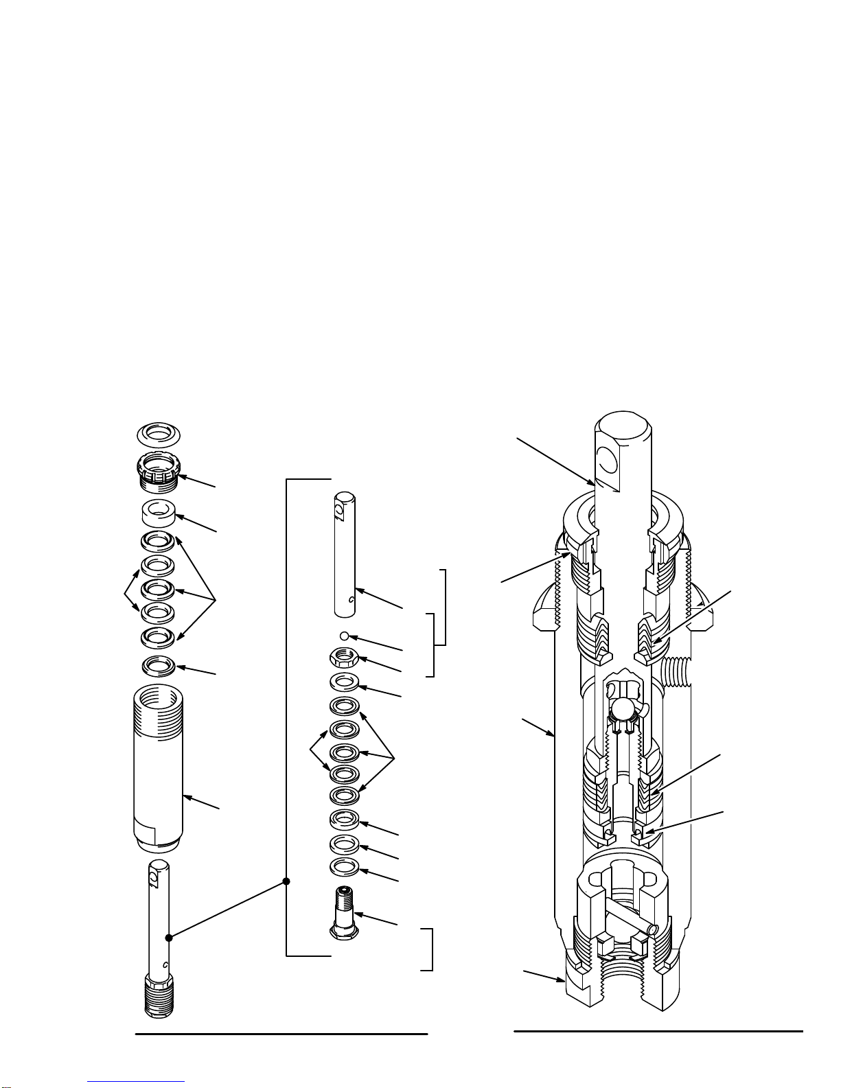
DISPLACEMENT PUMP
WARNING
To
reduce
the risk of serious bodily injury
, including
fluid
injection; splashing in the eyes or on the skin;
injury from moving parts or electric shock, always
follow the Pressure Relief Procedure Warning
on
page 12 before continuing.
Removing the Pump
Flush
the sprayer if possible.
Remove the hose clamps (87, 88) and move the drain
tube
(90) away from the
pump. Unscrew and remove the
suction
tube (52). Remove the adapter (50). See Fig 1.
Disconnect
the hose (20) from the nipple (22).
See Fig 1.
Push
the retaining spring
(55) up. Push out the pin (57).
Loosen
the cylinder locknut (103) and unscrew the pump
(26)
from the drive assembly (65).
See
Disassembling the Pump
, below
.
Installing the Pump
To reinstall the pump, rotate the crankshaft so that the
connecting
rod (64) is in its lowest position. Pull the pump
piston rod (47) about 1–1/2 inches out of the cylinder
(46), and turn the rod so the pin hole is about
90
_from
the
outlet nipple
(22). Screw the cylinder locknut (103) all
the
way down.
Screw
the pump (26) into the drive assembly (65) until the
holes in the piston rod and the connecting rod are
aligned.
Insert the pin (57) and push the retaining spring
(55)
down over the pin.
Screw the pump cylinder
completely
into the drive as-
sembly;
you will feel some resistance from the packings.
Now turn the cylinder back until the outlet nipple (22)
faces
back. Screw the hose (20) onto the nipple; tighten
it securely. To avoid having the cylinder locknut (103)
loosen
due to vibration, tighten the locknut up against the
drive
housing to 70 ft–lb (95 N.m).
Reassemble
remaining parts reverse from disassembly
.
NOTE: Use
Repair Kit No. 820–549 to repair the
pump.
See
page 23. Use all the parts in the kit, even if
the
old ones look good. Old and new parts do not
seal
together well, and the pump may leak.
Disassembling the Pump
Remove
the pump from
the sprayer as described above.
Unscrew the intake valve (48) from the cylinder (46). If
the valve is seized in the housing, squirt penetrating oil
around the threads and gently tap around the housing
with
a light hammer to loosen. See Fig 2 and 4. Remove
the ball guide (40), the stop pin (39) and the ball (28).
Clean
and inspect the parts for wear or damage.
NOTE: Test
the intake
valve by filling it with solvent and
seeing if any solvent leaks past the ball. It
shouldn’t leak. The valve must be clean for this
test;
any dirt will hold the ball of
f the seat and
let
the
solvent leak past.
Fig 1
Fig 2
88
87
90
65
55
64
57
20
22
26
52
46
28
40
41
48
39
47
50
103
0742
TORQUE
T
O
70 ft–lb
(95 N.m)
15
Unscrew
and remove the packing nut (38). Using a rub
-
ber mallet, tap the piston rod (47) down and pull it out
through
the bottom of the cylinder (46). See Fig 3 and 4.
Remove
the glands (34 &
37) and the packings (35 & 36).
Clean
and inspect
the piston rod and the inside of the cyl
-
inder for nicks, scratches or scoring which could cause
leaking
or premature wear of the packings.
Clamp
the
flats of the piston rod in a vise. Use a wrench
to loosen the nut (33) and unscrew the piston valve (49)
from the piston rod. Remove the ball (27), nut (33),
glands (30 & 32), packings (31 & 43), seal (29), and
washer (45).
Assembling the Pump
When
assembling the pump, coat the packings, the pis
-
ton
rod and the inside of the cylinder with oil.
When reassembling the piston, install the new glands
and
packings
in the correct order
, alternating the leather
and
plastic packings. See Fig 3. The “V”
of the packings
must
face
up against the fluid pressure. See Fig 4. T
ight-
en the nut (33) to 10.5 in–lb (1.2 N.m) to seat the pack-
ings,
then back of
f the nut and hand tighten it.
Place
a new ball (27) in the piston rod (47). Apply locking
compound to the threads of the piston valve (49) and
screw it into the rod hand tight, 1–2 in–lbs (0.11–0.22
N.m) torque. Tighten the nut against the piston rod to
18–20 ft–lb (24–27 N.m) torque, without changing the
tightness
of the nut against the packings.
Install
the throat packings, glands and packing nut, leav
-
ing the packing nut loose. The “V” of the packings must
face
down against the fluid pressure. Alternate the plastic
packings
(36) and the leather packings (35). See Fig 3.
Insert
the piston rod
(47) through the bottom of the pump
cylinder (46).
Assemble and install the intake valve (48); torque it to
75–85
ft–lb (100–1
15 N.m). T
ighten the packing nut (38)
just
enough to stop leakage––no tighter
.
Fig 3
38
37
36
35
34
46
47
27
33
32
43
31
30
29
45
49
TORQUE
T
O
1–2 in–lb
(0.1
1 – 0.22 N.m)
TORQUE TO
18–20 ft–lb
(24–27 N.m)
Fig
4
0743 0700
TORQUE
T
O
75–85 ft–lb
(100–1
15 N.m)
48
46
47
38 “V” FACES
DOWN
AGAINST
PRESSURE
“V” FACES
UP
AGAINST
PRESSURE
“U” FACES
DOWN
AGAINST
PRESSURE

16 820-008
CONNECTING
ROD AND BEARING
WARNING
To
reduce
the risk of serious bodily injury
, including
fluid
injection; splashing in the eyes or on the skin;
injury from moving parts or electric shock, always
follow the Pressure Relief Procedure Warning
on
page 12 before continuing.
Remove
the pump as described on page 14. Remove the
four screws (58) and the cover (59). Remove the two
capscrews
(61) and lockwashers (9). Remove the bear
-
ing
(63) and
the connecting rod (64), sliding the connect
-
ing
rod of
f the crankshaft. (J). See Fig 5.
Use
a screwdriver to push
the retaining spring (55) aside
and
remove the pin (57) from the
coupling (56). Remove
the
coupling from the connecting rod (64).
Pull
the connecting rod (64) out of the
bearing (63). Wipe
it
clean (don’t use solvent) and inspect the surfaces of the
bearing
and the connecting
rod link (K) for wear or dam
-
age. If either needs replacing, replace both of them.
When installing the rod and the bearing, coat the sur-
faces
with SAE 10 non–detergent motor oil.
Clean
and inspect
the crankshaft. (J). Wipe it clean with
a
rag; do not use solvent. If the crankshaft. is badly worn,
replace
the drive assembly
.
Clean
and inspect the connecting rod
needle bearing (L).
Repack bearing with industrial, heavy–duty, extreme–
pressure,
lithium–soap grease.
NOTE: After
every 100
hours of operation, or whenever
servicing the pump (whichever comes first), fill
the cavity in connecting rod (64) with SAE 10
non–detergent
motor oil.
Fig 5
64
63
55
56
57
9
61
59
58
J
K
L
LUBRICATE
– SEE NOTE IN TEXT
0745
Assemble new rod and bearing, being sure to push the
spring
(55) down in place over the pin (57) ends, and in
-
stall
it in reverse order of removal.
DRIVE ASSEMBLY
WARNING
To
reduce the risk of serious bodily in
-
jury, including fluid injection; splash-
ing in the eyes or on the skin; injury
from moving parts or electric shock,
always follow the Pressure Relief
Procedure
W
arning
on
page 12 be
-
fore
continuing.
Fig 6
25
24
70
69
68
24
67
66
A
B

17
Remove the pump, connecting rod and bearing as de-
scribed
on pages 14 and 16.
Remove
the capscrews (25 & 68), lockwashers (24), and
drive housing (A). Remove the screws (66), lockwashers
(67),
and motor housing (B). See Fig 6.
Clean
and inspect the gear (69)
for wear or damage. Re
-
place
it if necessary
. T
o remove the gear
, drive out the
pin
(70), and pull it off the motor shaft. Apply molybdenum
disulfide
spray lubricant to the new gear
, allow to dry
, then
apply
industrial, heavy–duty extreme–pressure,
lithium–
soap
grease.
Install new drive assembly in reverse order of removal.
CAPACITOR
WARNING
To
reduce
the risk of serious bodily injury
, including
fluid
injection; splashing in the eyes or on the skin;
injury from moving parts or electric shock, always
follow the Pressure Relief Procedure Warning
on
page 12 before continuing.
Unplug the sprayer. Remove the cover of the capacitor
(5).
See Fig 7.
Remove the flag connectors from the old
capacitor.
Connect the flag connectors of the new
capac
-
itor
and replace the cover
.
NOTE: The
replacement capacitor includes a new resis
-
tor
already installed.
ELECTRIC MOTOR
WARNING
To
reduce
the risk of serious bodily injury
, including
fluid
injection; splashing in the eyes or on the skin;
injury from moving parts or electric shock, always
follow the Pressure Relief Procedure Warning
on
page 12 before continuing.
Disconnect
the hose (20) from the nipple (22).
See Fig 1.
Remove the drive assembly as described above. You
can leave the pump, connecting rod, and bearing as-
sembled
to the drive assembly
.
Drive
out the pin (70) and remove the gear (69). See Fig
7.
Remove the screws (78) and the cover (79) from the
pressure
control (74). See Fig 8.
Disconnect the five motor leads.
Unscrew the nuts on both ends of the conduit (76) from
the
connector (75). Remove the screws (8), nuts (18) and
lockwashers
(9). See Fig 7. Lift
the motor (1) while care
-
fully
guiding the
wires through the connector in the con
-
trol box. Remove the conduit (76) from the wires.
Loosen
the locknut and unscrew the connector (75) from
the motor
, being careful to avoid twisting the wires.
Install the new motor in the reverse order of removal.
Fig 7 Fig 8
9
18
5
1
70
69
8RED
BLACK
BROWN
WHITE
GREEN
76
75
75
79
PINK
BLACK
POWER
SUPPLY
LEADS
GREEN
& YELLOW
MOTOR
LEADS
RED
WHITE
TRIAC
LEADS
1
74
WHITE

18
PRESSURE
CONTROL AND CIRCUIT BOARD
WARNING
To
reduce
the risk of serious bodily injury
, including
fluid
injection; splashing in the eyes or on the skin;
injury from moving parts or electric shock, always
follow the Pressure Relief Procedure Warning
on
page 12 before continuing.
NOTE: A circuit board (81) is not included with a new
pressure control (74). However, it is included
with
a new motor and it can be ordered separate
-
ly.
Be sure to order the correct circuit board. See
the
application information on page 22.
Do
not allow the fittings (A) to move when removing
the elbow (93) or tee (94) from the pressure con-
trol,
to avoid altering the
factory setting of the pres
-
sure
control or damaging the pressure control.
CAUTION
Circuit Board Removal
1. Remove
the pressure control cover (79). Pull the cir
-
cuit
board (81) out carefully
, just enough to reach the
wire terminals. Disconnect the leads. Remove the
board.
See Fig 10.
Pressure Control Removal
2.
Disconnect the hose (20). See Fig 9.
3. Disconnect the remaining two motor leads (black
and
green/yellow). See Fig 10.
4.
Remove the mounting screws (8). See Fig 9
.
5. Pull
the pressure control (74) away from the conduit
(76) and carefully guide the leads through the con-
nector
(75) one at a time. See Fig 10.
6. Remove
the mounting bracket (77).
Remove the fit
-
tings
(93,94). Install these
parts on the new pressure
control.
See Fig 9.
Pressure Control Installation
7. Guide
the motor leads into the new pressure
control.
8. Position
the circuit board (81) in the pressure control
so the wire connectors are at the top. Connect the
leads to the board as shown in Fig 10. Guide the
leads into the pressure control, making sure they
don’t
catch on anything. Slide the board into place.
9.
Connect any other loose wires. See Fig 10.
10.
Mount the pressure control on the cart.
11. ADJUST THE PRESSURE CONTROL! See page
19.
Adjust the pressure control whenever a new or
used pressure control or circuit board is installed,
to
reduce the risk of overpressurization which can
result in component rupture, fire or explosion. Im-
proper adjustment may also prevent the sprayer
from
obtaining the maximum working pressure, re
-
sulting
in poor sprayer performance.
WARNING
Fig 9
Fig 10
93
20
74
18 98
94
RED
BLACK
BROWN
WHITE
GREEN
76
75
75
79
PINK
BLACK
POWER
SUPPLY
LEADS
GREEN
& YELLOW
MOTOR
LEADS
WHITE
RED
WHITE
TRIAC
LEADS
1
74
81
A77

19
PRESSURE
CONTROL CALIBRA
TION
USE EXTREME CAUTION WHEN PERFORMING THIS CALIBRA
TION PROCEDURE
to reduce the risk of an
injection
injury or other
serious bodily injury which can result from component rupture, electric shock, fire, explo
-
sion,
or moving parts.
This
procedure sets the sprayer to 2750
psi (190 bar)
MAXIMUM
WORKING PRESSURE.
This
procedure must be performed whenever
micros
-
witch
or pressure control assembly is
removed and re
-
installed
or replaced to be sure the sprayer is properly
calibrated.
Improper calibration can cause the sprayer to over-
pressurize
and
result in component rupture, fire or ex
-
plosion.
It
may also prevent the sprayer from obtaining
the
maximum working pressure which would result in
poor sprayer performance.
NEVER
try to increase the fluid outlet pressure by per
-
forming these calibrations in any other way. Normal
operation
of the sprayer at higher pressures could re
-
sult
in component rupture, fire or
explosion. T
o perform
this adjustment, however, the sprayer pressure must
be
temporarily
increased above the normal working
pressure.
Use
a new 50 foot (15.2 m)
spray hose rated for 3000
psi (210 bar) MAXIMUM WORKING PRESSURE
when
performing this procedure. A used, under–rated
hose
could develop a high pressure leak or rupture.
WARNING
Service T
ools Needed:
DItems
in Fig 1
1D
5 gallon pail and water
D
Needle valve, P/N
D
3/8 in. socket wrench
102–715 or 103–067
D
Mineral spirits
Fig
1
10785
TEE,
104–984
FLUID FILLED
PRESSURE
GAUGE, 102–814
NEW
50 FT
. , 3000 PSI
FLEXIBLE NYLON
AIRLESS SPRA
Y
HOSE, 223–541
NIPPLE, 162–453
1. Relieve
pressure. See page 12.
2. Plumb the pressure control with additional parts as
shown in Fig 11. Connect the needle valve to the
open
end of the hose.
NOTE:
See Fig 12 for the following procedure.
3.
Remove the cover (79) and plug (123).
4. Open the needle valve slightly. Turn the pressure
control
knob (A) to the minimum setting.
5. Plug in and turn on the sprayer. Increase the pres-
sure setting just enough to start the sprayer. Prime
the
hose and purge all air from the system.
6. Open
the needle valve
a little more––enough to allow
the pump to run continuously––and turn the pressure
control knob to maximum. Now, very slowly start to
close
the needle valve, but don’t
close it all the way
.
Observe the pressure at which the pump stalls,
which
should be approximately 2750 psi (190 bar)
.
NOTE: The
slower the pressure is raised, the easier it
is
to note the exact stall pressure. Closing the
needle
valve quickly causes the pressure to rise
too
fast which gives a false reading.
If the pressure is lower than
2750 psi (190 bar)
:
Unplug the sprayer. Relieve pressure. Insert the
socket wrench through the plug hole and untighten
the
pressure adjustment nut 1/8 turn or less, then re
-
peat
steps 5 and 6.
If the pressure is higher than
2750 psi (190 bar)
:
Unplug the sprayer. Relieve pressure. Insert the
socket
wrench through the plug hole and tighten the
pressure
adjustment nut 1/8 turn or less and repeat
steps
5 and 6. Repeat this procedure until the proper
stall
pressure is obtained.
7. Now
check to see at what pressure
the sprayer starts
to
run again after it stalls. Plug in the sprayer
, turn it
on, close the needle valve, and set the pressure at
maximum.
Allow the sprayer to run until it stalls.
8. Open the needle valve very slowly while observing
the pressure gauge. Check to see if the pressure
drops to approximately 2350 psi (164 bar) before
starting
again.
If the pressure is not
2350 psi (164 bar)
:
Shut off and unplug the sprayer, but do not relieve
pressure. Turn the differential wheel (D) just one
notch
and repeat Steps 5 and 6. Check the pressure
drop
again and repeat if necessary
.
NOTE:
Always recheck the stall pressure (steps 5, 6)
if
the dif
ferential wheel was adjusted.
9. Follow
the
Pressure Relief Procedure W
arning
on
page
12. Flush the water out with mineral spirits. Re
-
lieve pressure again. Install the plug (123) and cover
(79).
Remove the test equipment.
Fig 21
ON/OFF
SWITCH
A
B
D
TIGHTEN
C0750

20
PARTS LIST
Model
820–002, Series F
Includes items 1–125
REF
NO. PART NO. DESCRIPTION QTY REF
NO. PART NO. DESCRIPTION QTY
1 820-621 MOT
OR, electric, 0.75
HP: includes
items 5, 7, 81, 104, 105,1
19 1
3 820–252 LOCKWASHER 2
5 820–339 CAPACITOR 1
7 185–952* LABEL, DANGER, English 1
8 820–257 CAPSCREW
, hex hd, 5/16–18 x 7/8”
7
9 820–258 LOCKW
ASHER, spring, 3/8”
9
13 820–469
RING, retaining, ext.
2
16 820–333 WHEEL 2
18 820–267 NUT
, hex, 6–32
7
19 820–578 VAL
VE, pressure relief
1
20 820–524
HOSE, nylon, 1/4” ID, 1/4 npsm (fbe),
29” (740 mm), spring guards
1
22 820–421 NIPPLE 2
24 820–273 LOCKW
ASHER (part of Ref No. 65)
5
25 820–274
CAPSCREW (part of Ref No. 65)
3
26 820–377 DISPLACEMENT PUMP
See page 23 for parts
1
50 820–350
ADAPTER, 3/8(m) x 1/2 npt(f)
1
52 820–481 TUBE, suction 1
54 820–303 STRAINER 1
55 820–304
SPRING, retaining
2
56 820–305 COUPLING, pump 1
57 820–306 PIN, str
, hdls, 0.3125” dia. x 1.02” lg
2
58 820–307 SCREW 4
59 820–308 COVER, gearcase 1
60 820–004
LABEL, identification
1
61 820–309 CAPSCREW
, socket head,
5/16–18 x 7/8”
2
63 820–311 BEARING 1
64 820–312 CONNECTING ROD 1
65 820–313 DRIVE ASSEMBL
Y Includes
replacement items 24, 25, 66–68
1
66 820–314 .CAPSCREW
, socket head, 3/8–16x1”
4
67 820–315 .LOCKWASHER 4
68 820–316 .CAPSCREW
, 1/4–20 x 3/4”
2
69 820–317
GEAR, pinion
1
70 820–318 PIN 1
71 820–319 T
AG, Caution
1
73 820–006
LABEL, identification
1
74 820–321 PRESSURE CONTROL ASSEMBLY
See page 22 for parts
1
76 820–473 CONDUIT
, electrical
4 in.
77 820–324 BRACKET
, mounting
1
78 820–560 SCREW 4
79 820–551 COVER, pressure control 1
80 820–327
LABEL, identification
1
81 820–618
BOARD, circuit (included in Ref No. 1)
see page 22 for application
information
1
87 820–343 CLIP
, spring
1
88 820–344 CLIP
, spring
1
90 820–346
TUBE, drain, 3/8” OD
1
92 820–619 THROAT SEAL LIQUID (TSL), 8 oz. 1
93 820–410 ELBOW
, street, 1/4 NPT
1
94 820–414
TEE, street, 1/4 npt(fbe), male run
2
95 820–474
PLUG, tubing
2
99 820–478 SCREW
, mach, hex hd, 1/4–20 x
2–3/4” 2
100 820–479 HOOK, pail 1
101 820–480 SPACER 2
103 820–291 NUT
, hex, 1–1/2 –18
1
104 820–526
TERMINAL, wire, female, snap–on
see page 22
4
105 820–428
TERMINAL, wire, ring
see page 22
1
117 820–533 CAR
T ASSEMBLY
1
118 820–263 HUBCAP 1
119 185–955* LABEL, DANGER, French 1
121 820–579 CONNECT
OR, tube
1
122 820–413 SCREW
, thread forming
4
124 820–620
LABEL, identification
1
125 186–126* LABEL, CSA Accessories 1
*Additional
W
arning labels available free.
Call Graco Customer
Service
at 1–800–328–021
1.
SERVICE INFORMATION
This manual has been updated to include new illustra-
tions, improved text, particularly in the pressure control
calibration on page 19, and circuit board ordering infor-
mation
on page 22.
Listed by the assembly changed are added parts.
Assembly
Changed Part
Status Ref
No. Part No. Name
820–002,
Sprayer to
Series F
Add 125 186–126 Label
Table of contents
Other Sherwin-Williams Paint Sprayer manuals

Sherwin-Williams
Sherwin-Williams ULTIMATE 824-030 User manual

Sherwin-Williams
Sherwin-Williams 820-206 User manual

Sherwin-Williams
Sherwin-Williams 820-169 Series B User manual

Sherwin-Williams
Sherwin-Williams NOVAspx 824-012 User manual

Sherwin-Williams
Sherwin-Williams PT2500 User manual

Sherwin-Williams
Sherwin-Williams ULTIMATE NOVA 1000 User manual

Sherwin-Williams
Sherwin-Williams ProComp 3800 User manual

Sherwin-Williams
Sherwin-Williams 820169 D Series User manual

Sherwin-Williams
Sherwin-Williams ULTIMATE Plus+ 1000 User manual

Sherwin-Williams
Sherwin-Williams 820-001 User manual


