Shihlin electric SDE-010A2U User manual

i
Preface
We appreciate very much for your purchasing of Shihlin servo products. This manual will be a
helpful instruction to install, wire, inspect, and operate your Shihlin servo drive and motor.
Before using the servo drive and motor, please read this user manual to prevent from electric
shock, fire, and injury.
In this manual, the safety instruction levels are classified into "DANGER" and "CAUTION".
It indicates that incorrect operation may cause hazardous
conditions, resulting in death or injury.
It indicates that incorrect operation may cause hazards,
resulting in injury to person or damage to the product.
Note that the CAUTION level may lead to a serious consequence by cases. Be sure to follow
the instructions of both levels to keep personnel safety well.
What must not be done and what must be done are indicated by the following marks:
: It indicates what must not be done.
: It indicates what must be done.
In this manual, instructions at a lower level than the above, instructions for other functions, and
so on are classified into "NOTE".
After reading this user manual, always keep it accessible to the operator.
!

ii
1. To prevent electric shock, please confirm the following:
Operate the power switches with dry hand to prevent an electric shock.
Before wiring or inspection, switch power off and wait for more than 10 minutes. Then,
confirm if the power indicator is off or the voltage is safe with voltage meter. Otherwise, you
may get an electric shock.
Connect the servo drive and motor to ground.
Do not attempt to wire the servo drive and motor until they have been installed. Otherwise,
you may get an electric shock.
The cables should not be damaged, stressed, loaded, or pinched. Otherwise, you may get
an electric shock.
2. To prevent fire, note the following:
Install the servo drive, motor and regenerative brake resistor in a clean and dry location
free from corrosive and inflammable gases or liquids. Otherwise a fire may be caused.
Don‟t try to operate the servo drive or motor which has become faulty. Otherwise, a large
current flow may cause a fire.
Do not connect a commercial power supply to the U, V, W terminals of drive. Otherwise a
fire may be caused and the servo drive will be damaged.
When an external regenerative brake resistor is used, check the specification
recommended. Otherwise, a regenerative brake transistor fault or the like may overheat
the regenerative brake resistor, causing a fire.
3. To prevent injury, note the following:
The proper voltage specified in this manual should be applied to each terminal, Otherwise,
a burst, damage, etc. may occur.
Ensure that polarity (+,-) is correct. Otherwise, a burst, damage, etc. may occur.
Ensure that all screws, connectors and wire terminations are fixed on the power supply,
servo drive and motor to prevent from a burst, damage, or personal injury.
Don‟t touch either the drive heat sink or the motor during operation because they may
become hot and cause personnel burnt.
Don‟t approach or touch any rotating parts (e.g. shaft) to prevent from serious injury.

iii
4. Other instructions
The following instructions should also be fully noted. Improper operation may cause a damage,
fault, injury or electric shock, etc.
(1) Delivering and installation
Delivery the products correctly according to their weights.
It is not allowed to stack the products in excess of the specified layers.
Do not carry the motor by the cables, shaft or encoder.
Do not hold the front cover to transport the drive. Otherwise, it may be dropped.
The servo drive and motor must be installed in the specified direction.
Inside control box, preserve enough space between the servo drive and other equipment.
Provide adequate protection to prevent screws and other conductive matter, oil and other
combustible matter from entering the servo drive.
Do not drop or strike servo drive or servo motor. Keep from all impact loads.
Use the servo drive and servo motor under the specified environmental conditions.
Firmly attach the servo motor. Otherwise, it may come off during operation.
For safety of personnel, always cover the rotating and moving parts.
Never impact the servo motor or shaft, especially when coupling the servo motor to the
machine. The encoder may become faulty.
Do not subject the servo motor shaft to more than the permissible load. Otherwise, the
shaft may be broken.
When the equipment has been stored for an long period time, consult Shihlin.
(2) Wiring
In order to prevent from fire or other accidents, please use the cable specified in this user
manual to wire the servo equipment.
Wire the servo drive correctly and firmly. Otherwise, the motor will run improperly.
Do not install a power capacitor, surge absorber or noise filter between the servo motor
and servo drive.
Do not connect AC power directly to the servo motor. Otherwise, it results in damage of
servo motor.
The surge absorbing diode installed on the DC output signal relay must be wired in the
specified direction. Otherwise, the emergency stop and other protective circuits may not
operate.

iv
(3) Trial run
The initial trial run for servo motor should be operated under idle conditions (separate the
motor from its couplings and belts).
Before trial run, check if the parameters are set properly. Otherwise it will cause some
unexpected operation.
The parameter settings must not be changed excessively. To adjust the parameters setting
gradually to meet your demand operation.
Ensure to perform trial run before your normal operation to prevent unexpected accident.
(4) Duty operation
Set an external emergency stop circuit. It could stop operation immediately as unexpected
accidents occurred.
Before resetting an alarm, make sure that the run signal is off to prevent a sudden restart.
Use a noise filter to minimize the influence of electromagnetic interference, which may be
caused by electronic equipment used near the servo drive.
Do not mismatch the servo drive and motor in capacity.
The electromagnetic brake on the servo motor is designed to hold the motor shaft and
should not be used for ordinary braking.
For heavy duty case (e.g. where a huge load inertia or short acceleration/deceleration time
setting), the external regenerated brake resistor is necessary.
(5) Maintenance and Inspection
Ensure that the power indicator is off before maintenance or inspection performed.
Only personnel who have been trained should conduct maintenance and inspection.
Do not try to disassemble the servo drive or motor which any fault occurred.
Do not connect or disconnect the servo drive with motor while power is still applied.
As power is still applied, not to touch any internal or exposed parts of servo drive and servo
motor to prevent electrical shock.
Some parts inside the servo drive are consumable and should be replaced periodically. For
parts replacement, please consult Shihlin.
NOTE : This manual may be revised without prior notice. Please consult our agent or
download the most updated version at http://www.seec.com.tw/en/ .

v
1. Product descriptions.......................................................................................................1
1.1 Summary.....................................................................................................................1
1.2 Drive model designation..............................................................................................1
1.3 Motor model designation.............................................................................................2
1.4 Drive rating plate .........................................................................................................3
1.5 Motor rating plate ........................................................................................................4
1.6 Function block diagram ...............................................................................................5
1.7 Combinations of Servo Drive and Servo Motor ...........................................................6
1.8 Servo control mode .....................................................................................................6
1.9 Drive appearance and panel descriptions (1kW or less).............................................7
1.10 Drive appearance and panel descriptions (1.5kW or greater)...................................8
1.11 Wires with peripheral equipment...............................................................................9
2. Installation......................................................................................................................10
2.1 Cautions....................................................................................................................10
2.2 The environment conditions of installation.................................................................10
2.3 Installation direction and clearances .........................................................................11
2.4 Encoder cable stress.................................................................................................12
3. Wiring and signals.........................................................................................................13
3.1.Input power source circuit..........................................................................................14
3.2.Description of drive terminals and sockets................................................................15
3.3.CN1 I/O socket..........................................................................................................16
3.3.1. CN1 pin assignment .......................................................................................16
3.3.2. Shielding and ground for CN1 cable...............................................................17
3.3.3. CN1 pin name list ...........................................................................................18
3.3.4. CN1 pin function description...........................................................................19
3.3.5. CN1 DI signals................................................................................................21
3.3.6. CN1 DO signals..............................................................................................26
3.3.7. Interface wiring diagram .................................................................................30
3.4.CN2 Encoder signal wiring and description...............................................................34
3.5.CN3 communication port signal wiring and description.............................................35
3.6.CN4 USB communication port...................................................................................35
3.7.CN5 battery power socket.........................................................................................36
3.8.Standard wiring method.............................................................................................37
3.8.1. Wiring diagram of position control(Pr Mode)...................................................38
3.8.2. Wiring diagram of position control(Pt Mode)...................................................39
3.8.3. Wiring diagram of speed control(S Mode) ......................................................40
3.8.4. Wiring diagram of torque control(T Mode)......................................................41
4. Startup............................................................................................................................42

vi
4.1.Switching power on for the first time..........................................................................42
4.1.1. Startup procedure...........................................................................................42
4.1.2. Wiring check...................................................................................................43
4.1.3. Ambient environment......................................................................................44
4.2.Display and operation................................................................................................45
4.3.Display flowchart .......................................................................................................46
4.4.Status display............................................................................................................47
4.5.Diagnostic display .....................................................................................................49
4.5.1. Indication of external I/O signals.....................................................................50
4.5.2. DO forced output ............................................................................................51
4.5.3. Test operation.................................................................................................52
4.6.Automatic offset of analog input ................................................................................55
4.7.Alarm display.............................................................................................................56
4.8.Parameter display .....................................................................................................57
4.9.Startup in various control modes...............................................................................60
4.9.1. Startup in position control mode .....................................................................60
4.9.2. Startup in speed control mode........................................................................61
4.9.3. Startup in torque control mode .......................................................................63
5. Parameters.....................................................................................................................64
5.1.Parameter definition ..................................................................................................64
5.2.Parameter list............................................................................................................65
5.3.Parameter details list.................................................................................................81
6. Gain adjustment and control mode............................................................................122
6.1.Different adjustment methods..................................................................................122
6.2.Auto-gain tuning mode ............................................................................................124
6.3.Manual gain tuning mode........................................................................................127
6.4.Interpolation mode...................................................................................................128
6.5.Torque control mode................................................................................................129
6.5.1. Output proportion of maximum torque analog command..............................129
6.5.2. Torque analog command offset.....................................................................130
6.5.3. Torque analog command smoothing.............................................................130
6.5.4. Torque limit of torque control mode...............................................................131
6.5.5. Speed limit of torque control mode...............................................................132
6.6.Speed control mode ................................................................................................133
6.6.1. Selection of speed command........................................................................133
6.6.2. Output speed of maximum speed analog command.....................................134
6.6.3. Speed analog command smoothing .............................................................134
6.6.4. Torque limit of speed control mode...............................................................137

vii
6.6.5. Adjustment of speed loop gain......................................................................138
6.6.6. Resonance and vibration suppression filter..................................................140
6.6.7. Gain switch function......................................................................................143
6.7.Position control mode..............................................................................................147
6.7.1. External pulse-train command (Pt mode) .....................................................147
6.7.2. Inner register command (Pr mode)...............................................................149
6.7.3. Position command smoothing.......................................................................150
6.7.4. Electronic gear..............................................................................................151
6.7.5. Torque limit of position control mode ............................................................153
6.7.6. Position loop gain .........................................................................................153
6.8.Control mode switch................................................................................................154
6.8.1. Position/speed mode switch .........................................................................155
6.8.2. Speed/torque hybrid mode ...........................................................................155
6.8.3. Torque/Position control mode switch ............................................................156
6.9.Other functions........................................................................................................157
6.9.1. Selection of brake resistor............................................................................157
6.9.2. Analog monitor output...................................................................................160
6.9.3. Operation of electromagnetic brake interlock ...............................................162
7. PR (procedure) sequence control introductions ......................................................163
7.1.PR introduction........................................................................................................163
7.2.PR differences in SDAand SDE..............................................................................163
7.3.DI/DO and sequences.............................................................................................164
7.4.Relevant parameter settings of PR..........................................................................165
8. Communication functions ..........................................................................................172
8.1.Communication interface and wiring .......................................................................172
8.2.Relevant parameters of communication..................................................................173
8.3.Modbus protocol......................................................................................................174
8.4.Communication parameter write-in and read-out ....................................................181
9. Troubleshooting...........................................................................................................188
9.1.Alarm list..................................................................................................................188
9.2.Alarm cause and remedy.........................................................................................190
10. Specifications ..............................................................................................................201
10.1. Drive specifications...............................................................................................201
10.2. Drive dimensions..................................................................................................203
10.3. Motor specifications..............................................................................................206
10.3.1.Low inertia, small capacity motor specifications..........................................206
10.3.2.Medium capacity, low inertia motor specifications.......................................208
10.3.3.Medium capacity, medium inertia motor specifications................................209

viii
10.4. Motor dimensions .................................................................................................211
10.4.1.Dimensions of motors (3000rpm rated speed) ............................................211
10.4.2.Dimensions of motors (2000rpm rated speed) ............................................212
10.4.3.Motor shaft end specification.......................................................................213
10.5. Motor characteristic ..............................................................................................214
10.6. Overload protection ..............................................................................................218
11. Compliance with global standards.............................................................................220
11.1. About safety..........................................................................................................220
11.2. Professional engineer...........................................................................................220
11.3. Standard compliance............................................................................................220
11.4. Correct use...........................................................................................................222
11.5. Inspection and maintenance.................................................................................224
11.5.1.Basic inspection...........................................................................................224
11.5.2.Maintenance................................................................................................224
11.5.3.Life of consumable components..................................................................224
12. Appendix ......................................................................................................................225
12.1. Options .................................................................................................................225
12.2. Brake resistor........................................................................................................229
12.3. Parameter communication address......................................................................230
12.4. Version information...............................................................................................234

1
1. Product descriptions
1.1 Summary
The Shihlin SDE series general-purpose servo drive has higher performance and more functions
compared to the previous Shihlin servo drives. The Shihlin SME series servo motor is equipped with
22-bit (4,194,304 pulses/rev) high resolution encoder. The servo drive has position, speed, and torque
control modes. In the position control mode, the maximum pulse train of 4 Mpps is supported. There
are 4 basic control modes: position mode with external command, position mode with inner command,
speed mode, torque mode. Further, it can perform the control modes switched, e.g. position/speed
mode switched, speed/torque mode switched and torque/position mode switched. Therefore, the SDE
servo drive are suitable for the general industry machinery that require the high precision and smooth
speed control, or machine tools, or tension control.
With the auto tuning gain function, the drive could automatically adjust the control gain according to
the instant dynamic change of the user’s machinery.
The SDE drives equip not only RS-485 serial communication but also the most convenient device
“USB” which could be connected to the personal computer performing the parameter setting, test
operation, gain adjustment, and others.
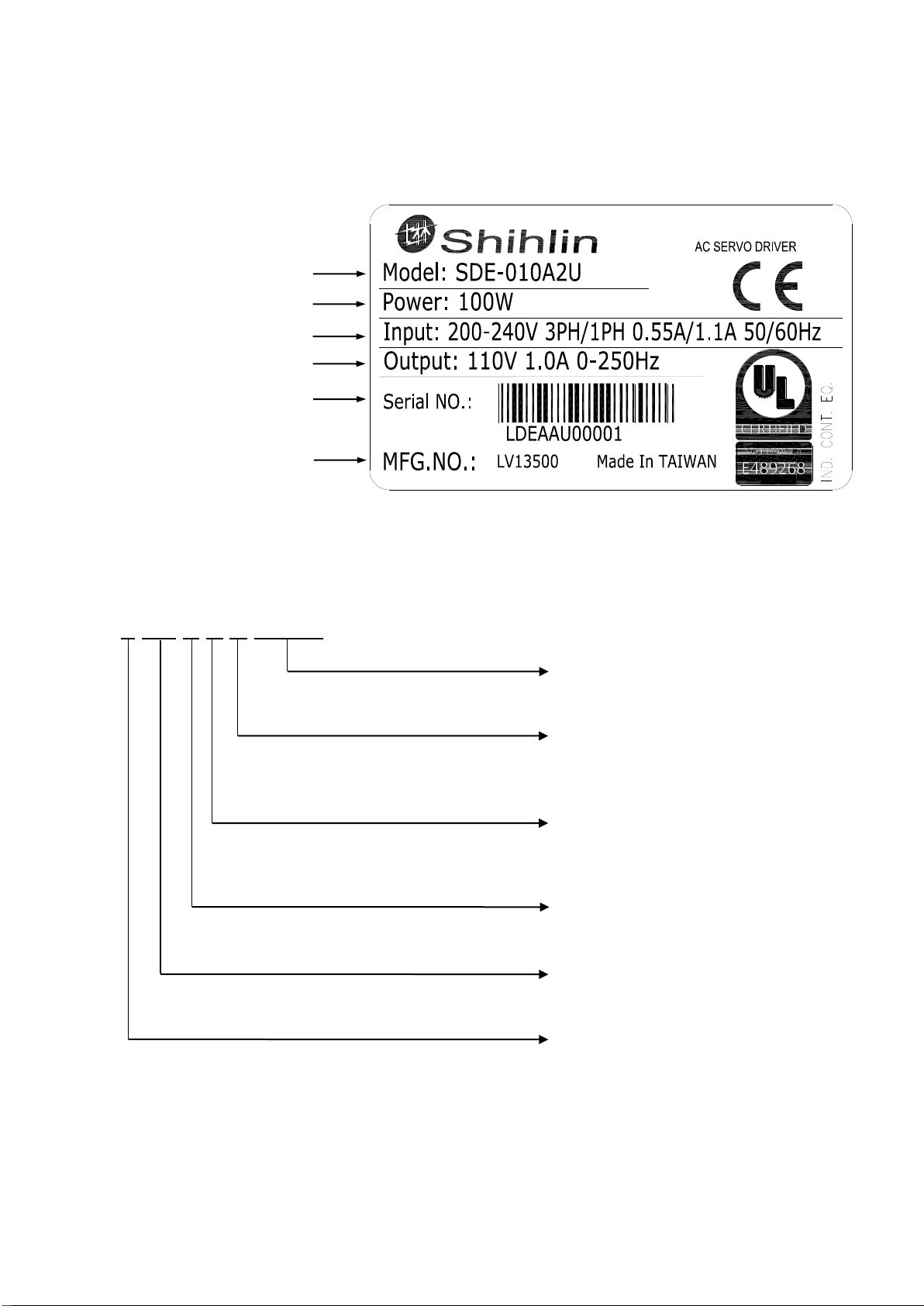
1.2 Drive model designation
S D E - ○○○ A2 U - * *
Symbol
International approval
U
UL+CE
-
CE
Symbol
Power voltage (V)
A2
220
Symbol
Rated output (kW)
010
0.1
020
0.2
040
0.4
075
0.75
100
1
150
1.5
200
2
300
3
Shihlin general purpose AC
servo drive SDE series
Shihlin definition/Customer ID code

2
1.3 Motor model designation
SME-□○○○ ΔΔ○□□□-XY
Shihlin servo motor
SME series
Symbol
CE
approval
UL
approval
-
○
X
U
○
○
Symbol
Inertia class
L
low
M
medium
Symbol
Back side
cable
Keyway
shaft
A
X
X
B
X
○
C
○
X
D
○
○
Symbol
Rated output
(kW)
005
0.05
010
0.1
020
0.2
040
0.4
075
0.75
100
1
150
1.5
200
2
300
3
Symbol
Oil seal
brake
A
X
X
B
X
○
C
○
X
D
○
○
Symbol
Rate speed
(rpm)
20
2000
30
3000
Symbol
Encoder type
S
Single turn, 22bit/rev
M
65536 turns, 22bit/rev
Shihlin definition/
Customer ID code
3
1.4 Drive rating plate
(1) Rating plate diagram
(2) Serial number description
L DE A A U 00001
Model
Capacity
Applicable power
Rated output current
Serial number
Number of manufacture
Number
00001~99999
Certification code
U: UL approved
C: CE approved
Type code
A: 010
B: 020
…
Applied power voltage
A: 220V
Drive series code
DE: SDE series
Country of origin
L: Taiwan
S: Suzhou in China

4
1.5 Motor rating plate
(1) Rating plate diagram
(2) Serial number description
L ME A B U 00001
Model
Applicable power
Rated output current
IP class, Standards
Serial number
Number of manufacture
Number
00001~99999
Certification code
U: UL approved
C: CE approved
Type code
A: 005
B: 010 …
Motor series code
ME: SME series
Country of origin
L: Taiwan
S: Suzhou in China
Motor features
Symbol
Encoder
type
Oil seal
Brake
Back side
cable
Keyway
shaft
A
S
X
X
X
X
B
S
X
X
X
○
…

5
1.6 Function block diagram

6
1.7 Combinations of Servo Drive and Servo Motor
1.8 Servo control mode
Control Mode
Sign
Description
Basic
Position with
external command
Pt
Drive receives the pulse commands of a superior controller then runs
the motor to reach the assigned position.
Position with inner
command
Pr
According to the parameters setting and DI signals, drive runs the
motor to reach the assigned position.
Speed
S
Drive runs motor to attain the target speed. The command type which
is an analog voltage or the inner registers could be switched by DI.
Torque
T
The drive receives the commands to run the motor to generate the
demanded torque. The command source is the analog voltage.
Switched
Pt-S
Pt/S is switched mutually via the LOP signal of DI.
Pt-T
Pt/T is switched mutually via the LOP signal of DI.
Pr-S
Pr/S is switched mutually via the LOP signal of DI.
Pr-T
Pr/T is switched mutually via the LOP signal of DI.
S-T
S/T is switched mutually via the LOP signal of DI.
Servo drive
Servo motor (Note)
Low inertia series
Medium inertia series
SDE-010A2
SME-L005
-
SDE-010A2
SME-L010
-
SDE-020A2
SME-L020
-
SDE-040A2
SME-L040
-
SDE-075A2
SME-L075
-
SDE-100A2
SME-L100
SME-M100
SDE-150A2
SME-L150
SME-M150
SDE-200A2
SME-L200
SME-M200
SDE-300A2
SME-L300
SME-M300
7
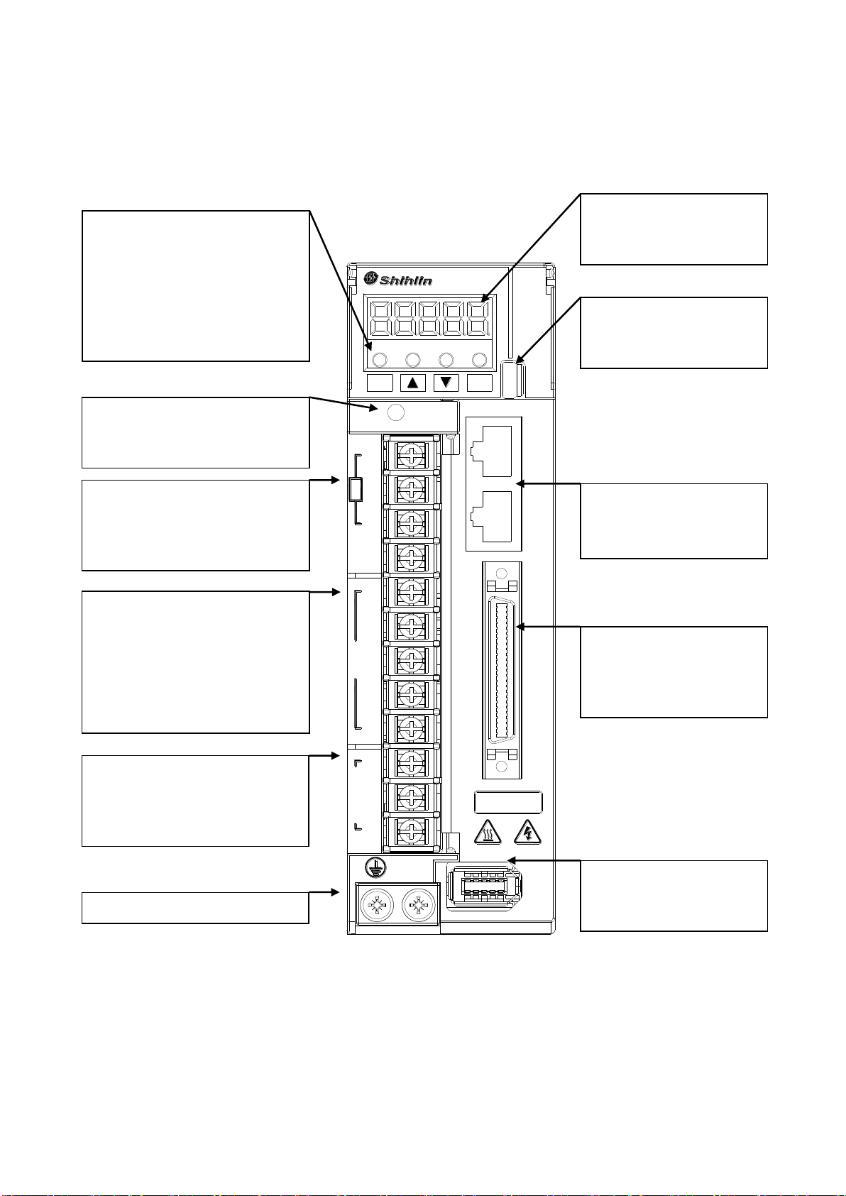
1.9 Drive appearance and panel descriptions (1kW or less)
Note: 1. If an external brake resistor is applied, please make sure that “P” and “D” connect to the
resistor, and make “P” and “C” open. If an active brake unit is applied, connect “P” and “N” to
the unit and make “P” and “C” and “D” open.
SDE-010A2
MODE SET
CHARGE
+P
D
BR
C
-N
L1
L2
R
S
T
220V
U
W
MOTOR
CN2 CN1 CN3 CN3L CN4
V
Display:
Drive status, alarm number,
parameter are displayed.
USB port:
Connect a PC or compatible
superior controller.
Power indicator:
To indicate the remainder voltage
of servo drive.
RS485 port:
Connect a PC or compatible
superior controller.
50-pin DI/DO socket:
An I/O signal socket with
particular signals for various
applications
Encoder socket:
Used to connect the servo
motor encoder
Brake resistor terminals:
Install an external resistor if large
inertia load applied and frequent
regeneration. (Note 1)
Auxiliary power input:
Connect L1/L2 to the single phase
AC 200~240 volt power 50/60 Hz.
Main power input:
Connect R/S/T to commercial 3
phase AC 200~240 volt 50/60Hz
Output power terminals:
Connect U/V/W to servo motor in
sequence. Do not confuse U/VW
with R/S/T, it cause damage.
Ground terminals:
Operation keys:
Parameter setting, monitoring etc.
are executed with 4 keys.
MODE:
mode selection
▢: +1 incremental key
▼: -1 decreased key
SET : confirm key

8
1.10 Drive appearance and panel descriptions (1.5kW or greater)
Note: 1. If an external brake resistor is applied, please make sure that “P” and “D” connect to the
resistor, and make “P” and “C” open. If an active brake unit is applied, connect “P” and “N” to
the unit and make “P” and “C” and “D” open.
SDE-300A2
+P
D
BR
C
-N
MODE SET
CN3 CN3L CN4
CHARGE
R
L1
220V
L2
S
T
U
MOTOR
V
W
220V
CN1
CN2
Display:
Drive status, alarm number,
parameter are displayed.
Operation keys:
Parameter setting, monitoring
etc. are executed with 4 keys.
MODE:
mode selection
▢:
+1 incremental key
▼: -1 decreased key
SET : confirm key
USB port:
Connect a PC or compatible
superior controller.
Power indicator:
To indicate the remainder
voltage of servo drive.
50-pin DI/DO socket:
An I/O signal socket with
particular signals for various
applications
Encoder socket:
Used to connect the servo
motor encoder
Brake resistor terminals:
Install an external resistor
if large inertia load applied
and frequent regeneration.
(Note 1)
Main power input:
Connect R/S/T to
commercial 3 phase AC
200~240 volt 50/60Hz.
Output power terminals:
Connect U/V/W to servo
motor in sequence. Do not
confuse U/VW with R/S/T,
it cause damage.
Ground terminals:
USB port:
Connect a PC or compatible
superior controller.
Auxiliary power input:
Connect L1/L2 to the
single phase AC 200~240
volt power 50/60 Hz.

9
1.11 Wires with peripheral equipment
Peripheral equipment connected to the servo drive is described as below. The wires with the
peripheral equipment is an example for SDE-040 or smaller. Connectors, cables, options, and other
necessary equipment should be ready so that users can set up the servo easily and start using it right
away.
Note: 1. A single phase AC 200~240 volt power supply may be used with the servo drive of
SDE-200A2 or less. In such case, connect the power supply to R and T. Leave S open.
Note: 2. If an external brake resistor is applied, please make sure that “P”and “D”connect to the
resistor, and make “P”and “C”open. Or an active brake unit is applied, connect “P”and “N”
to the unit and make “P”and “C”and “D”open.

10
2. Installation
2.1 Cautions
Do not install the product on inflammable matters or close to inflammable matters.
Do not over tighten the wire between the drive and the motor.
Do not place heavy objects on the top of the drive.
Be sure to tight lock every screw when fixed the drive.
Install the drive at a location where could bear the weight of the drive.
Align the axle of the motor and the axle of the machinery device.
Inflammable objects or conductive objects are not allowed inside the drive.
Upgrade the diameter of the U/V/W wires and the encoder cable if the length between the
drive and the motor is over 20m.
Do not clog up the vent of the drive or breakdown may be occurred.
Do not drop or clash the drive.
Not try to run the drive which something has been damaged.
Please refer to section 11.1 and 11.3 for drive and motor storage details.
2.2 The environment conditions of installation
The surrounding air temperature suitable for Shihlin drive is between 0 °C and 55 °C. If it is higher
than 45 °C, the installation place with good ventilation or air conditioner is necessary. For a long-time
operation, place the drive in an environment with temperature below 45℃to ensure the reliability of the
drive. If the drives are installed in a distributor, make sure that its size and ventilation condition to
prevent from over-heat. Make sure that mechanical vibration will not affect the electronic devices of the
distributor. In addition, the use of Shihlin servo shall meet the following criteria:
Locations without high-heating devices.
Locations without floating dust and metal particles.
Locations without corrosive, inflammable gas and liquid.
Locations without water drops, steam, dust or oil dust.
Locations without electromagnetic interference.
Select a solid, vibration-free location.

11
2.3 Installation direction and clearances
The drive must be installed in the specified direction. Otherwise, it may
cause a malfunction.
Leave specified clearances between the drive and the cabinet walls or
other devices. Otherwise, it may cause a malfunction.
(1) Installation direction
(2) Installation clearances of one drive
(3) Installation clearances of two or more drives
Leave a large clearance between the top of the servo drive and the cabinet walls. When mounting
the servo amplifiers closely, a cooling fan to is helpful to prevent the internal temperature of the cabinet
from exceeding the endurance of servo drive. In this case, keep the surrounding air temperature within

12
0 °C to 45 °C or use the servo amplifier with 75% or less of the effective load ratio.
(4) Others
When using a regenerative device is used, consider a well ventilation so that the servo drive is not
affected. Install the servo amplifier on a perpendicular wall in the correct vertical direction.
2.4 Encoder cable stress
(1) The way of cable clamping must be fully examined so that bending stress and cable's own weight
stress are not applied to the cable connection.
(2) Any application which the servo motor moves, fix the cables (encoder, power supply, and brake)
with having some slack from the connector connection part of the servo motor to avoid putting
stress on the connector connection part. Use the optional encoder cable within the bending life
range.
(3) Use the power supply and brake wiring cables within the bending life of the cables.
(4) Avoid any probability that the cable coat might be cut by sharp chips, rubbed by a machine corner or
stamped by workers or vehicles.
(5) For installation on a machine where the servo motor moves, the bending radius should be made as
large as possible.
This manual suits for next models
9
Table of contents
Other Shihlin electric DC Drive manuals

Popular DC Drive manuals by other brands

Pentair
Pentair Pentek Intellidrive XL quick start guide

TECHTOP
TECHTOP TD20 Series product manual

GE
GE D8R4 instructions

Rexnord
Rexnord Falk A Series Assembly & installation

Pentair
Pentair PENTEK INTELLIDRIVE PID2000-1123 installation manual

Franklin Electric
Franklin Electric Cerus X-Drive quick start guide


Simu
Simu T845/10 K manual

STG-BEIKIRCH
STG-BEIKIRCH M2 Series Technical information and operating instruction

BONFIGLIOLI Vectron
BONFIGLIOLI Vectron Agile Communications manual

TECO
TECO MV510 Series user manual

Siemens
Siemens SINAMICS V20 Series Easy start guide

Sumitomo Drive Technologies
Sumitomo Drive Technologies eye LM2 Gears CMS user manual