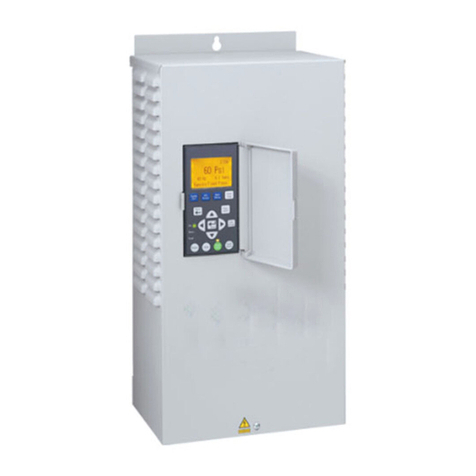
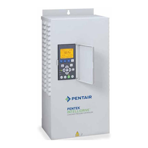
Pentair PENTEK INTELLIDRIVE PID2000-1123 User manual

INSTALLATION MANUAL
PENTEK INTELLIDRIVE™
PID2000-1123
www.onga.com.au
©2010 PNX900 (Rev. 9/14/10)
Installation/Operation/Parts
For further operating, installation, or maintenance assistance:
Call 1-300-137-344

Table of Contents 2
Owner’s Information.................................................................................................................................. 2
General Safety ........................................................................................................................................... 3
Description / Typical Installation................................................................................................................ 4
Keypad Nomenclature & Functions ........................................................................................................... 5
Installation................................................................................................................................................. 6
Connections........................................................................................................................................... 6–8
Programming ......................................................................................................................................... 8–9
Advanced Programming....................................................................................................................... 9–11
I/O Connections .......................................................................................................................................12
Troubleshooting ................................................................................................................................. 13–15
Wire Sizing Tables ................................................................................................................................... 15
Repair Parts.............................................................................................................................................. 16
Specifications ...........................................................................................................................................16
Warranty.................................................................................................................................................. 16
Owner’s Information
PENTEK INTELLIDRIVE Model No. _____________________________________
PENTEK INTELLIDRIVE Serial No.______________________________________
Pump Model No. ____________________________________________________
Pump Serial No. _____________________________________________________
Motor Model No._____________________________________________________
Motor Service Factor Amps ____________________________________________
Pressure Tank Model No.______________________________________________
Pressure Tank Serial No. ______________________________________________
Dealer/Installer: _____________________________________________________
__________________________________________________________________
Installer Phone No.___________________________________________________
Date of Installation ___________________________________________________
Wire Lengths in Feet (Metres)
Circuit Breaker to PENTEK INTELLIDRIVE_____________________________
PENTEK INTELLIDRIVE to Motor _______________________________________
Supply Voltage ______________________________________________________
Note: Record the data listed above for future reference. Give the manual to the
owner or fasten it to the PENTEK INTELLIDRIVE when the installation is complete.
EMI/RFI Filter
Hazardous voltage.
Drive internal
components retain
high
voltage for up to
5 minutes after input
power is disconnected.
EMI/RFI Filter carries
high voltage when
pump is running.
Disconnect power and
wait 5 minutes before
opening and removing
VFD cover.

GENERAL SAFETY
Read the Owner’s Manual and related documentation
carefully before attempting to install or operate the
PENTEK INTELLIDRIVETM. Make sure that you have a full
knowledge of the equipment, safety information, and
instructions before using this product.
Carefully read and follow all safety instructions in this
manual and on the VFD.
This is the safety-alert. When you see this symbol
on your VFD or in this manual, look for one of the
following signal words and be alert to the potential for
personal injury:
warns about hazards that will cause
serious personal injury, death or major property damage if
ignored.
warns about hazards that can cause
serious personal injury, death or major property damage if
ignored.
warns about hazards that will or can
cause minor personal injury or property damage if ignored.
The word NOTE indicates special instructions which are
important but not related to hazards.
To avoid serious or fatal personal injury and possible
property damage, carefully read and follow the safety
instructions.
Risk of high-voltage electrical shock
from the EMI/RFI Filter if the front cover of the VFD is
open or removed while power is connected to the VFD or
the VFD is running. The front cover of the VFD must be
closed during operation.
• After allowing at least 5 minutes for the EMI/RFI Filter
to discharge and before starting any wiring or
inspection procedures, check for residual voltage with
a voltage tester.
Risk of electrical shock if VFD is
connected to the power wiring before hanging the box.
Always hang the VFD box before connecting the wires to it.
Risk of electrical shock if the VFD is
handled or serviced with wet or damp hands. Always
make sure your hands are dry before working on the VFD.
Perform all operations on the HMI with dry hands.
Risk of electrical shock and hand
injury. Do not reach into or change the cooling fan while
power is on to the VFD.
Risk of electrical shock. Do not touch
the printed circuit board when power is on to the VFD.
Fire hazard if installed with incorrect or
inadequate circuit breaker protection. To make sure of
protection in the event of an internal fault in the VFD,
install the VFD on an independent branch circuit protected
by a circuit breaker (see Table 2, Page 6 for circuit breaker
sizing), with no other appliances on the circuit.
Risk of burns. The drive can become
hot during normal operation. Allow it to cool for 10
minutes after shut-down before handling it to avoid burns.
Risk of electric shock. A means for
disconnection from the supply mains, having a contact
separation in all poles, must be incorporated in the fixed
wiring in accordance with the wiring rules.
Complex equipment. This device is not
intended for use by persons (including children) having
reduced physical, sensory or mental capabilities, or lack of
experience and knowledge.
NOTE: This VFD is classified as Class A EMC/EMI
equipment. It is intended for use in an industrial
environment. There may be potential difficulties ensuring
electromagnetic compatibility in other environments due
to conducted as well as radiated disturbances.
NOTE: The device must be supplied through a Type A
Residual Current Device (RCD) having a rated residual
operating current not exceeding 30 mA.
NOTE: To avoid damage to the drive or problems with the drive:
• Connect the output cables to 3-wire submersible
motors as described in Output Connections, page 7.
Any other order will reverse the motor rotation and
may damage the motor.
• Do not modify the equipment.
• Do not use power factor correction capacitors with this
VFD; they will damage both the motor and the VFD.
• Do not remove any parts unless instructed to do so in
the owner’s manual.
• Do not use a magnetic contactor on the VFD for
frequent starting/stopping of the VFD.
• Do not install or operate the VFD if it is damaged or
parts are missing.
• Before starting a VFD that has been stored for a long
time, always inspect it and test operation.
• Do not carry out a megger (insulation resistance) test
on the control circuit of the VFD.
Safety 3
Risk of high-voltage electrical shock
from EMI/RFI Filter inside Drive.
Make all wiring connections, then
close and fasten the cover before
turning on power to Drive.
DO NOT open the box when power is
connected to the Drive.
Before doing any service
or maintenance inside
the Drive:
1. DISCONNECT power.
2. WAIT 5 minutes for
retained voltage to
discharge.
3. Open box.
Before connecting or
disconnecting any wires
inside the Drive:
1. DISCONNECT power.
2. WAIT 5 minutes for
retained voltage to
discharge.
3. Open box.

• Do not allow loose foreign objects which can conduct
electricity (such as screws and metal fragments) inside
the VFD box at any time. Do not allow flammable
substances (such as oil) inside the VFD box at any
time.
• Ground the VFD according to the requirements of the
Wiring Rules (AS/NZS 3000) and any other codes and
ordinances that apply.
• All installation, service work, and inspections must be
done by a qualified electrician.
Carefully read and follow all safety instructions in this
manual or on device.
PENTEK INTELLIDRIVE Includes:
• PENTEK INTELLIDRIVETM
• Pressure Transducer
• 3 Metre Pressure Transducer Cable
• Quick Start Guide
• Owner’s Manual
The PENTEK INTELLIDRIVE is specifically designed to
operate 4” submersible pumps. Each drive is rated for
maximum output amp rating. Any use of the drive
outside of its intended use and design parameters will
void the warranty.
Transducer
The drive uses a 4-20mA, 0-690 kPa pressure transducer to
control the speed of the motor.
The transducer senses pressure in the pipe and converts it
to an electrical signal which it sends to the drive. The drive
processes the signal in the PID (Proportional, Integration,
Derivative) control. When operating in PID mode the drive
increases and decreases the speed of the pump motor as
needed to maintain constant pressure in the system.
Description / Typical Installation 4
6226 0710
Transducer; install in straight
pipe at least 32 cm away from
pipe fittings on each side.
NOTE: Enclosures rated IP22
require Water Proof Cable Gland
GND
20 cm
or more
20 cm
or more
Figure 1: Overall Layout – Typical installation

Keypad 5
Table 1: Model Number Structure
Voltage Rating:
1= 190–265 Volt 1 phase input
Output Voltage:
1= 220V 1 phase output
PID2000 – 1 – 1 – 2 – 3
PID2000-1123:
Product Family
PID2000 = Pentek IntelliDrive
HP Rating:
2= 2.0 HP
Motor Type:
3= 3-wire
Fan
The PENTEK INTELLIDRIVE has a thermostatically
controlled internal fan. The fan may not operate under
normal operating conditions. It will automatically start
when necessary to cool the drive.
Keypad
The Keypad programs the drive, monitors the status of the
pump, and views faults if they occur. Each button has a
unique function (see Figure 2). The LCD display shows a
text display of the status of the drive’s operation. Other
LEDs light up to indicate when certain buttons are pressed
or certain events occur.
Runs the Drive at 40 Hz
(with no pressure control)
to allow the installer
to pump out the well
Toggles the pressure setpoint
between 300, 400, and 500 kPa;
default is 400 Views and changes parameters
Shows the last 15 faults
Changes the display to
the previous screen With code, locks and unlocks the
password protected keys (default
password is 7777)
Selects menu items and
confirms numeric value changes
The up and down arrows scroll through
the menus and change numeric values.
Toggles between English, Spanish,
and French (Default is English )
The left and right arrows
move the cursor.
Power is on to the Drive
The Drive is in Temporary Performance
Mode (TPM) or Jam condition
A fault has occurred
Displays the Drive’s
current operating conditions and
changes the display parameters
Checks for line fill, then
starts the pump in constant
pressure mode
Resets the fault
that stopped the pump
Stops the motor
6007 0509 EX
Hazardous
pressure.
Do not connect to
system or restrict
discharge flow
when running in
“Pump Out”
mode.
Figure 2: Keypad functions
Keypad Nomenclature and functions

INSTALLATION
Mounting (See Figure 3)
Mount the drive in an easily accessible area with
temperature maintained between –4°F and 104°F (–20°C to
40°C). The drive may be mounted outdoors.
To mount the drive, mark the location of the top keyhole
on the wall or stud. Drive a screw into the structure and
hang the drive on it. Back out the screw on the bottom of
the front cover and lift the cover off. Mark the locations of
the bottom two mounting holes. Mount the drive with
screws in all three holes.
Be sure that the ventilation holes are not blocked and that
there is enough space around the drive to allow free air
flow (minimum 75mm clearance, top, bottom, and sides).
Once the drive is mounted, you are ready to connect
the wires.
Wiring
To allow for ease of wiring, the wiring area is free of
electronics other than the terminals. Conduit holes and
knockouts are located so that the wire can be fed straight
through to the connectors, with minimal bending. The
terminals accept 1.5 to 4.0mm2wire.
NOTE: For convenience in wiring, the input and motor
terminals unplug from the box. Pull them down to remove
them for ease of access. See Figure 4.
BE SURE that when you replace them, they are completely
pushed in and seated.
Note: The best practice is to connect all output wires first
and all input wires last.
Installation 6
Minimum 240VAC
Controller Wire Size C.B. Size Generator
Model No. CB to VFD (Amps) Capacity (kVA)
PID2000-1123 2.5mm230 7.4
Table 2: Circuit Breaker and Wire Sizes
Figure 4: Pull the input and motor terminals down
to unplug them for ease of wiring.
NOTE: The circuit breaker protects the drive and is chosen independently
of the motor connected to the drive.
5997 0509 EX
Figure 3
Typical 220-240 Volt
Circuit Breaker
(Double Width)

Connections 7
Output Connections (See Figure 5, Page 7):
See Table 6, Page 15, for correct wires sizes, VFD to motor.
The output of PID2000 Series drives is 220V single phase
power.
The output power terminals (motor wire connections) are
located on the lower right side of the drive and are labeled
R (Red), Y (Yellow), and B (Black). Feed the motor cable
through the 20mm conduit hole on the bottom right side
and into the appropriate terminals. If the wire is large
enough to require a larger conduit hole, remove the 32mm
knockout and use the appropriate conduit connections.
Attach the motor ground wire to the grounding lug, located
to the upper right of the terminal block. Attach the motor
power wires to the terminals as shown in Figure 5. Table 3
lists the required wire color attachment scheme.
Table 3: Motor Wiring Connections
Pressure Tank Recommendations:
Minimum tank size is 8 litres. Use a pre-charged pressure
tank with the Drive. The tank size must equal at least 20%
of the pump’s rated flow in litres per minute (LPM), but
cannot be less than 8 litres capacity. For example, a pump
rated at 30 LPM would require a tank of 8 litres capacity
or larger. A pump rated at 150 LPM would require a
30 litre tank or larger. A larger tank may increase cycling
of the pump.
Table 4: Control Pressure Set Point and
Tank Pre-Charge Pressure Values
NOTE: Set the pressure tank’s pre-charge to 70% of the
system operating pressure. When using an external set
point as well as an internal set point, pre-charge the tank
to 70% of the lower set point of the two. Some
applications may require a different percentage when
figuring the set point.
Transducer Connections (See Figure 5):
Use the transducer provided with the drive. Install the
transducer downstream of the tank. Install the transducer in
a tee in a straight section of pipe with at least 1 foot of
straight pipe on each side of the tee (that is, all fittings
must be at least one foot away from the transducer).
Feed the transducer cable through the open 12mm conduit
hole on the bottom of the drive enclosure.
Pressure Setpoint Precharge Pressure
(kPa) (kPa)
200 140
250 175
300 210
350 245
400 (Default) 280
450 315
500 350
550 385
600 420
650 455
Aust EUR USA Code
Main/Run Winding Blue Blue/Grey Black B
Start/Aux Winding White Black Red R
Common Red Brown Yellow Y
Cable Shield
Red to AI+
Black to AI–
Transducer Cable
Connections
Submersible Motor: 3-W. 1-Ph.,
follow colors as shown in Table 3.
Cable Shield Lug
Output Ground Screw
Input Power Connections
Input Ground Screw
See Figures 6–9, Page 12, for information
about I/O Connections O1, I1,V+, and V–.
Green/Yellow
(Ground) Green/Yellow
(Ground)
6184 0310 EX
Figure 5: Basic Wiring Connections for Startup.

The transducer terminals, marked AI+ and AI-, are located
to the left of the output terminals. Connect the red wire of
the transducer cable to AI+, connect the black wire to AI–,
and connect the cable shield to the metal lug to the right.
NOTE: Do not use the clear wire on the transducer cable
for any connections; tape the end and tie it back to the
cable with electrical tape so that it does not touch any
other components or connections.
Note: To connect the wires;
1. If the wire ends are not pre-stripped, strip them back
about 12mm.
2. Push the spring terminals up (back).
3. Insert the wires.
4. Release the spring terminals.
Input Connections (See Figure 5):
The input power terminals are located on the lower left
side and marked L1 and L2 (see Figure 5); there is a
ground lug for the input ground wire to the left of the
connector. Feed the wire through the 20mm conduit hole
on the bottom left side and into the appropriate terminals.
If the wire is large enough to require a larger conduit hole,
remove the 32mm knockout and use the appropriate
conduit connections.
To determine the correct wire sizes for your installation,
see Table 2, Page 6.
NOTE: The drive only accepts 190-265V single phase input
power. If your incoming power does not match this, have a
competent electrician alter it to 220V or 240V nominal
1Ph before connecting the drive.
Lightning/Surge Protection
Lightning arrestors or other surge suppressing devices can
be used with this product. MOV (Metal Oxide Varistor),
SOV (Silicon Oxide Varistor), or a flashover type can be
used when wired between the drive and the circuit breaker.
If a lightning arrestor is to be used between the drive and
the motor, a flashover type arrestor is recommended.
INITIAL STARTUP
PROGRAMMING
PROCEDURE
Be Sure that the cover is installed before operating the drive.
Most installations will only require the initial startup
settings. However, the installer may need to set additional
parameters occasionally. See “Advanced Programming”,
Page 9, for information about accessing all parameters,
explanations of their functions, and procedures for
changing parameter values, if necessary.
1. Program the Drive: Apply power to the PENTEK
INTELLIDRIVE. “Setup Guide” will appear.
A. Service Factor Amps (See Sidebar, “Service Factor
Amps”)
1. Use DIRECTIONAL Arrows to enter the correct
service factor amps (see Table 4)
2. Press ENTER to save the entry.
B. Application Type:
1. Use DIRECTIONAL Arrows to scroll between
‘Above Ground’ and ‘Submersible’.
2. Press ENTER to save.
C. Current Time:
1. Use DIRECTIONAL Arrows to scroll to correct
time
2. Press ENTER to save the time.
D. Current Date:
1. Use DIRECTIONAL Arrows to scroll to
correct date
2. Press ENTER to save the date.
• To change any values, press Back to return to the
previous screen.
• To change any values after startup, go to Main Menu
and edit the parameters as needed.
Connections / Operation 8
Service Factor Amps (See Table 5)
To get the best performance out of your pump, be
sure you enter the correct Service Factor Amps
(SF Amps) in the PENTEK INTELLIDRIVE.
• Entering SF Amps
higher
than the motor rating
lets the drive supply more amps to the motor than
the motor is designed for and may allow the motor
to overheat;
• Entering SF Amps
lower
than the motor rating
limits the output amps to less than the motor is
designed for and will reduce the performance of
the pump.
• For any 1-Phase 3-Wire motor, the correct Service
Factor Amp rating for the PENTEK INTELLIDRIVE
is Cap Start/Cap Run amps. This may not match
the motor nameplate, which (for a 3-Wire, Single
Phase motor) will generally be Cap Start/
Induction Run Amps.
NOTE: Global submersible motors may differ from
motors of the same horsepower from other
manufacturers. For 3-Wire, 1-Phase motors from
all other submersible motor manufacturers, enter
the motor manufacturer’s CS/CR service factor
amps for your motor.
Part Number Volts/Hz/Ph HP kW S.F. Amps
3-Wire Single Phase Motors
G43A0010B2 220/50/1 1.0 0.75 6.4
G43A0015B2 220/50/1 1.5 1.1 9.4
G43A0020B2 220/50/1 2.0 1.5 11.6
Table 5: Global Motor Service Factor Amps

Operation / Programming 9
2. Pump out the well (if necessary):
Direct the pump’s discharge to an appropriate
location not connected to the system and press Pump
Out. The pump will run at 40 Hz.
Adjust frequency as appropriate:
A. Press ENTER
B. Change frequency value
C. Press ENTER again to save the value.
Run the drive in this mode until the well discharge
runs clear, then press the ‘Stop’ button to stop the
drive.
Hazardous pressure. In Pumpout
mode, the pump runs at a constant speed, which can
cause very high pressure if flow is restricted.
3. Check List:
Make sure that the system has a properly sized relief
valve and pressure tank.
Make sure that the pressure tank’s precharge is
correct. See Table 4, Page 7.
Make sure that the pump discharge is connected to
the system.
4. System Start:
Open valves at the ends of lines so that air will escape
during pressurization.
Press Auto Start; close valves at the ends of lines after
all air has escaped.
The system goes into Constant Pressure Operation as
soon as the transducer registers 70 kPa. If system
pressure does not reach 70 kPa within 3 minutes, the
drive will stop. Press AutoStart again to restart line fill.
If a longer priming or line fill time is required, adjust
the ‘fill time’ parameter in the ‘dry run’ menu
(Page 11).
ADVANCED PROGRAMMING
Locking & Unlocking the Keypad
Password: The password locks or unlocks the blue buttons
on the keypad. All PENTEK IntelliDrive units are shipped
from the factory with the default password ‘7777’. It can
be changed to any other 1 to 4 digit number. To reset the
password to a unique password for your unit, unlock the
key pad (see below) and go to “SETTINGS/Password”,
Page 10.
If the installer does not press the PASSWORD button, then
the Keypad will automatically lock 60 minutes after the
drive is powered up. The timeout period is adjustable
through the Main Menu/Settings/Password.
To unlock the keypad press PASSWORD, use the
directional arrows to enter the proper numeric code, and
press ENTER.
NOTE: For more detailed information on Keypad functions,
see the “Parameters” section.
Changing a Parameter Value:
NOTE: This procedure works for ANY parameter.
1. Find the parameter and display the current parameter
value on the screen.
2. Press ENTER to enable editing of the parameter.
3. Use the UP, DOWN, LEFT, and RIGHT arrows to
change the parameter values.
4. Press ENTER again to save the new parameter value.
NOTE: A “shorthand” way to remember this is:
• Press ENTER to change a value;
• Press ENTER again to save it.
• If you don’t save the new value, then as soon as you
change the screen, you lose it.
Keypad Access Parameters
Pump Out Speed: Press Pump Out. The Drive will start the
pump in a constant speed mode (default 40 Hz). The pump
will run until you push Stop or Auto Start. If necessary to
change the speed, Follow steps 2-4 above to change the
parameter.
Pressure Setpoint: Press Auto Start, then follow steps 2-4
above to change the parameter. Use the directional arrows
to change the pressure.
• NOTE: This parameter allows you to change either the
Internal or the External Setpoint, depending on which
one is referenced at the time you are making the change.
• NOTE: To change the setpoint before starting the pump,
go to the Main Menu/Settings/Setpoints/
Internal Setpoint.
• NOTE: If this value is changed from the default value of
400 kPa, you must adjust the tank pressure accordingly
(see Table 4, Page 7).
PSI Preset: Press PSI Preset; follow steps 2-4 above to
change the parameter. The default is 400 kPa, but the para-
meter can be set to 300, 400, or 700 kPa.
Language: Press Language; follow steps 2-4 under
“Changing a Parameter Value,” Page 9, using the UP or
DOWN arrows to scroll through the available languages
(English, French, or Spanish; default is English).
• NOTE: To change the setpoint before startup, go to the
Main Menu under “Settings”.
Main Menu Parameters
The Main Menu has six secondary menus (plus a Reset)
that allow access to the Advanced Programming
parameters: 1) SETTINGS, 2) MOTOR, 3) SENSOR, 4) PIPE
BREAK, 5) DRY RUN, 6) I/O. The basic structure and
navigation instructions are listed below. Use the UP and
DOWN arrows to scroll to the next secondary menu or
submenu, or to a parameter. Press Enter to go into a
Submenu or to edit a parameter.

1) SETTINGS: (Has 5 submenus)
Time (2 parameters):
Hour:
Allows you to change the time of day.
Date:
Allows you to change the calendar day.
PID Control: Changing these parameters is NOT
recommended. These parameters control the drive’s
reaction to pressure changes in the system. They should
be considered as a group. If it seems necessary to alter
anything in this group, please call Pentek Customer
Service at 1-300-137-344 BEFORE YOU START. Also,
note that the last item on the main menu resets ALL
parameters to the default values.
Sleep (6 parameters plus Reset):
Boost Differential:
Raises the system pressure
slightly before going into sleep mode. Units are in
PSI. The default boost value is 20 kPa. (i.e., with
Boost Differential set to 20 kPa and Pressure
Setpoint set to 400 kPa, the system pressure will
rise to 420 kPa before the drive goes to sleep).
Maximum is 70 kPa, minimum is 20 kPa.
Boost Delay:
The length of time (in seconds) that
the drive monitors the system before boosting the
pressure. Default is 60 seconds, maximum is
300 seconds, minimum is 30 seconds.
Wakeup Differential:
The total pressure drop from
the setpoint that the drive must see to come out of
Sleep mode. The default setting is 35 kPa (i.e., with
the Wakeup Differential set to 35 kPa, the drive
will wake up when the pressure in the system has
dropped 35 kPa below the system Pressure
Setpoint.) Maximum is 100 kPa, minimum is
35 kPa.
Wake Delay:
The time it takes to ramp down to the
Wake Up pressure. Default is 15 seconds,
maximum is 120 seconds, minimum is 3 seconds.
Sleep 2 PRESSURE:
A setting to prevent Over-
Pressure. If the system pressure rises enough that
the drive reaches the Sleep 2 PRESSURE setpoint,
the drive will go to sleep for one minute. Default
pressure is 550 kPa, maximum is ‘Max Sensor’
value minus 20 kPa, minimum is 100 kPa.
• NOTE: If the Internal or External Setpoint is set to
a value that is near, at, or above the
Sleep 2 PRESSURE setpoint, you may experience
nuisance tripping. In this case, raise the
Sleep 2 PRESSURE setpoint until the nuisance
tripping stops.
Boost Trigger:
Sets the frequency range that defines
system stability. When the frequency stabilizes
within this range, the drive starts the boost process.
Increasing this value allows the drive to sleep
under less stable conditions. The default is 3 Hz.
The range is 3 to 30 Hz.
Reset to defaults:
Default value is NO. Change to
YES to reset all Sleep parameters to their default
values.
Password (2 parameters):
Password Timeout:
Sets the time (in minutes) that
the drive takes to lock out the password-protected
(blue) buttons on the keypad. The range is
1 – 360 minutes; the default is 60 minutes. When
drive programming is complete, a timer starts.
Once it reaches the time set in this parameter the
buttons automatically lockout.
Password:
The Password locks or unlocks the blue
buttons on the keypad. The password is a number
(default is 7777) and can be changed to any 1- to
4-digit number.
Setpoints (2 Parameters):
Internal Setpoint:
The main pressure setting used by
the drive. The default value is 400 kPa. Maximum
is the ‘Max Sensor’ value minus 20 kPa, minimum
is 100 kPa.
External Setpoint:
The Drive’s pressure reference
when the External Input is set to External Setpoint
and the proper drive is connected to it (see I/O
section, Pages 11 and 12). Default is 300 kPa,
Maximum is ‘Max Sensor’ minus 20 kPa, minimum
is 100 kPa.
2) MOTOR (4 parameters plus Reset):
Service Factor Amps:
The service factor amps of the
motor. This value is entered during the setup
process and can be changed if necessary. For your
Global motor, use the value listed in Table 5,
Page 8. This value may differ slightly from the
motor’s nameplate amps. For other manufacturer’s
3-wire, 1-Phase motors, use the Cap Start/Cap Run
values supplied by the motor manufacturer.
Min Frequency:
The minimum frequency that the drive
will send to the motor (this translates to the slowest
speed at which the motor will run). The default is
30 Hz. If necessary this value can be increased, but
cannot exceed the Max Frequency value.
Max Frequency:
This is the maximum frequency
the drive will send to the motor (this translates to
the highest speed at which the motor will run).
The default is 50 Hz.
Reset to defaults:
Default value is NO. Change to
YES to reset all Motor parameters to their default
values.
Operation / Programming 10
Advanced Programming 11
3) SENSOR (2 parameters plus Reset):
Min Pressure (kPa):
The minimum pressure of the
transducer 0 kPa. The default is 0 kPa. Do not
change this value unless you are using a transducer
other than the one shipped with the drive, and the
transducer being used requires a different minimum
setting.
Max Pressure (kPa):
The maximum pressure of the
transducer 2000 kPa. The default is 690 kPa. Do
not change this value unless you are using a
transducer other than the one shipped with the
drive, and the transducer being used requires a
different maximum setting.
Reset to defaults:
Default value is NO. Change to
YES to reset all Sensor parameters to their default
values.
4) PIPE BREAK (2 parameters):
Pipe Break Detection:
Detects a possible leak in
the system. The Default value is ENABLED. Change
to DISABLE to disable Pipe Break Detection.
Number of days with no sleep:
The maximum
number of days that the drive will operate without
going to sleep. If the maximum is exceeded, the
drive stops the pump with a Pipe Break Fault.
Default is one day. Range is 1–24 days.
5) DRY RUN (5 parameters):
Auto Reset Delay:
The delay (in minutes) that the
drive will wait before attempting to restart after a
Dry Run Fault. Default is 10 minutes. Range is
3–60 minutes.
Number of Resets:
The number of times that the
drive will attempt to restart after a Dry Run Fault.
Default is 3. Range is 0–5.
Detection Time:
The amount of time the drive will
operate at less than 70 kPa. Default is 15 seconds.
Range is 5 to 600 seconds. For self primers,
increase value in the event of nuisance dry run
faults.
Fill Time:
The amount of time the drive will operate
in line fill mode. For self primers, increase value to
allow for priming. Default is 60 seconds. Range is
15 to 600 seconds.
Reset Window (Read Only):
The time window
allowed for resets after a Dry Run Fault. This is
calculated based on the values in the two
parameters above (Auto Reset Relay and Number
of Resets).
6) I/O (Two Submenus):
External Input (4 parameters – see Figures 6 through 9,
Page 12).
NOTE: An external device must be connected before
changing these parameters:
Unused:
The default.
Setpoint:
Used with devices like automatic
sprinkler systems that start and stop on a timeclock.
When the timeclock starts the system, SETPOINT
tells the drive to operate at the External Setpoint
pressure (under the Settings menu) until the
external device switches off.
External Fault:
Stops the pump and indicates
EXTERNAL FAULT. Used to alert the user to
problems with external devices.
Run Enable:
Used with external switches (for
example, float switches) connected to I1 to allow
the drive to operate when the external switch is
ON, and stops the drive when the external switch
is OFF.
Relay Output (3 Settings—See Figures 6 through 9,
page 12):
Unused:
Selected when nothing is connected to
the O1 terminals.
Running:
Can turn an external device on or off
when the drive is running the pump.
Fault:
Can turn an external device (such as an
alarm or autodialer) on or off if the drive has a
fault.
Reset to Factory defaults:
Change NO to YES to reset all the parameters in the VFD
(including all sub-menus) to the factory-set default values.
NOTE: This will display the startup menu. You must re-enter
the information required for startup (see “Initial Startup
Programming Procedure”, Page 8).

The I/O terminals are located in the center of the wiring
compartment, to the left of the transducer terminals. The
Relay Output terminal is marked O1. The Relay Output
terminal powers an external device (warning light, etc.).
The External Input terminal is marked I1. The External Input
terminal allows the Drive’s operation to be coordinated
with or limited by an external device (float switch, etc.).
Each can be programmed for use with certain external
devices.
Two 12mm conduit knockouts are provided on the bottom
of the drive enclosure for the I/O wires.
External Input Rating:
The unique design of the PENTEK INTELLIDRIVE allows
this input to be 24V DC or 24-240V AC. Power can be
supplied (24VDC) from terminals V+ and V– to the right of
I/O terminal I1. See Figures 6 and 7.
Output Relay Rating:
The unique design of the PENTEK INTELLIDRIVE allows
this output to be 24V DC or 24-240V AC. Power can be
supplied (24VDC) from terminals V+ and V– to the right of
I/O terminal I1. See Figures 8 and 9. The Output Relay is
rated at 5A @ 30VDC or 8A @ 240VAC.
Note: To connect the wires to either terminal:
1. Strip the wires back about 1/2”.
2. Push the spring terminals up (back).
3. Insert the wires.
4. Release the spring terminals.
The 24VDC supply terminals (V+ and V–) are rated for
20ma output.
I/O Connections 12
+
–
Figure 7: External Input using external power
supply (can also be an A.C. source).
Figure 6: External Input using 24VDC and power
from terminals V+/V–.
Figure 8: Output relay example using 24VDC
supply.
+–
Figure 9: Output relay example using external
supply.
NOTE: The external input and output relay can accept 24VDC. It also accepts AC voltage up to 240 volts.

Troubleshooting 13
Fault Display Possible Causes Actions
Over Shorted output. Check for any shorts in the motor cables.
Current Motor current exceeded the S. F. Amp Make sure that motor Service Factor Amps
are correct.
Motor oversized or pump undersized. Make sure that pump and motor are sized
correctly.
Pump Jammed or locked rotor. Pull pump; check for debris in pump
Over Power is cycling on and off. Check for a generator or for switching on
Voltage the input line.
Faulty check valve on pump. Check for back flow in the system.
Under Low input voltage. Make sure that input voltage is above
Voltage 190VAC
No power for a short period of time. Check for brown out conditions
Excessive load current. Make sure motor is sized correctly for the
application
Loss of a motor phase. Make sure correct voltage is present on all
motor leads.
Loss of an input line. Make sure correct voltage is present on all
input lines.
Rotor Jam Exceeding S.F. Amps Make sure Service Factor Amps entered
are correct.
Make sure pump and motor are correct.
Locked rotor. Pull pump; check for debris in pump.
Dry Run Well draws down too far, pump runs dry. Check water depth.
Under sized pump or motor. Make sure pump and motor are sized
correctly.
Leak in the pipe system. Check system for leaks.
Intermittent transducer connection. Check transducer cable for loose
connections or damaged insulation.
Cannot reach pressure setpoint. May need to reduce pressure setpoint.
Possible Leak Check for a broken pipe or a large leak.
Ground Ground fault sensed in motor Make sure motor cable does not exceed
Fault cables or in motor. max length in specifications.
Check for damage or breaks in motor
cables.
Check motor.
Motor cable too long Length of cable limited to 1,000’ unless a
filter is used to reduce capacitance
between motor wires.
Open Intermittent connection. Check transducer cable for loose
Transducer connections or broken or damaged wires.
Open Connection Check transducer wires for correct
connections and verify secure cable
connection to transducer.
Failed transducer. Check voltage at the transducer terminals
(12-24Vdc). If voltage is present, then
transducer is faulty. Replace the transducer.

Troubleshooting 14
Fault Display Possible Causes Actions
Shorted Short in transducer wires. Check for shorted transducer wires,
Transducer reversed leads, or damaged insulation.
Failed transducer. Disconnect transducer from cable and
press auto start; if the error now reads
“Open Transducer” (and leads are not
reversed) then replace the transducer. If it
still reads “Shorted Transducer”, then the
cable has a short; replace the cable.
Hard Exceeded Max faults allowed Check Fault log for list of faults. Correct
Faults in 30 minutes. issues. Press “Fault Reset”.
Any fault lasting continuously for Look in the Fault Log for the fault
30 minutes (including auto reset faults preceding the Hard Fault to determine
lasting more than 30 minutes). what caused the Hard Fault; refer to that
fault’s troubleshooting section.
Over Excessive internal drive temperature. Make sure that the ambient temperature is
Temperature not above 60°C (104°F)
Make sure that the fan is operational and
unobstructed.
Make sure that all vents are clear.
Drive goes into TPM and limits the motor
current until it is within the operating
temperature.
Pipe Break Leak detected. Check for any leaks in the pipe system.
Application calls for long run times. Extend run-time limitation: Go to ‘Main
Menu, Pipe Break, No. of Days without
Sleep’ to verify preset value and change if
needed.
Disable Pipe Break Fault: Go to ‘Main
Menu, Pipe Break, Disable Pipe Break
Detection’ to disable this function if
needed.
Internal Fault Internal voltages are out of range. Drive will auto reset and try to clear fault;
press Fault Reset to try to reset fault,
then try to run pump. If fault continues,
replace drive.
Hardware Internal hardware failure. Press Fault Reset to try to reset fault, then
Fault try to run pump.
If fault continues, replace drive.
External Fault External device detected a fault Check the external device.
condition and closed the I1 input.
Open Lead Motor has an open lead. Make sure that all motor lead connections
are tight and secure.
Motor’s thermal overload tripped. Wait for
it to cool and then restart pump.
Over Current Motor current has exceeded S F Amps. Drive goes into TPM and limits the motor
current.

Troubleshooting / Wiring Size Charts 15
Warning Cause Drive Operation
TPM: Service Motor current has exceeded S F Amps. Drive goes into TPM and limits the motor
Amps current.
TPM: Speed Drive internal temperature limit Drive goes into TPM and limits the motor
Reduced exceeded. current until it is within operating
temperature range.
Jam Warning Debris in pump has locked rotor. Drive reverses or pulses motor to try to
free it.
NOTE: No user action is required when a Warning is displayed.
Table 6: AWG Wire Sizing, VFD to 3-Wire, 1-Phase Motor.
NOTE: Information in this Table applies ONLY to Global Series motors. For other motors, refer to motor
manufacturer’s specifications for wire sizing.
VFD Global Volts/ Maximum Cable Length in Metres
Model Motor HP Hz/Ph kW Amps 1.5 mm22.0 mm22.5 mm23.5 mm24.0 mm2
3-Wire, 1 Phase
G43A0010B2 1.0 220/50/1 0.75 6.4 100 159 253 305
PID2000-1123 G43A0015B2 1.5 220/50/1 1.1 9.4 68 108 173 273 305
G43A0020B2 2.0 220/50/1 1.5 11.6 55 87 140 221 305

Repair Parts / Warranty 16
Part Description Qty. Part No.
Input Terminal Block Connector 1 PID-CON2
Output Terminal Block Connector 1 PID-CON3
Cooling Fan 1 PID-FAN-R
Pressure Transducer 1 U17-1561-R
10’ Transducer Cable 1 U18-1593
25’ Transducer Cable* 1 U18-1594
50’ Transducer Cable* 1 U18-1595
100’ Transducer Cable* 1 U18-1596
150’ Transducer Cable* 1 U18-1597
200’ Transducer Cable* 1 U18-1598
Cord Grip for Transducer Cable* 1 U17-1337
Keypad 1 PID-HMI-R
REPAIR PARTS
Drive:
Max Input Amps: . . . . . . . . . . . . . . . . . . . . . . . . . . .17A
Max Output Amps . . . . . . . . . . . . . .See Table 1, Page 5
Input/Output Terminal Capacity . . . . . . . . . .1.5-4.0mm2
Input Frequency . . . . . . . . . . . . . . . . . . . . . . . .50/60Hz
Input Voltage . . . . . . . .230VAC Nominal (190–265VAC)
Output Voltage: PID5 . . . . . . . .220VAC/30-50Hz/1 Ph
Output Connections . . . . . . . . . . . . . . . 3-Wire/1-Phase
Max Motor Cable Length . . . . . . . . . . . . . . . . . . .305 m
Ambient Temperature . . .–4°F to 104°F(–20°C to 40°C)
Transducer:
Pressure Range: . . . . . . . . . . . . . . . . . . . . . . .0-690 kPa
Output Signal: . . . . . . . . . . . . . . . . . . . . . . . . .4-20mA
Pressure Port: . . . . . . . . . . . . . . . . . . . . . . . . .1/4” NPT
Rated Voltage . . . . . . . . . . . . . . . . . . . . . . . .8–28VDC
SPECIFICATIONS
* Purchase Separately
LIMITED WARRANTY
PENTAIR WATER warrants to the original consumer purchaser (“Purchaser” or “You”) of the products listed
below, that they will be free from defects in material and workmanship for the Warranty Period shown below.
Product Warranty Period
PENTEK INTELLIDRIVE 12 months from date of original installation, or
18 months from date of manufacture
Our warranty will not apply to any product that, in our sole judgement, has been subject to negligence,
misapplication, improper installation, or improper maintenance. Without limiting the foregoing, operating a
three phase motor with single phase power through a phase converter will void the warranty.
Your only remedy, and PENTAIR WATER’s only duty, is that PENTAIR WATER repair or replace defective
products (at PENTAIR WATER’s choice).You must pay all labor and shipping charges associated with this
warranty and must request warranty service through the installing dealer as soon as a problem is discovered.
No request for service will be accepted if received after the Warranty Period has expired. This warranty is not
transferable.
PENTAIR WATER SHALL NOT BE LIABLE FOR ANY CONSEQUENTIAL, INCIDENTAL, OR CONTINGENT
DAMAGES WHATSOEVER.
THE FOREGOING WARRANTIES ARE EXCLUSIVE AND IN LIEU OF ALL OTHER EXPRESS AND
IMPLIED WARRANTIES, INCLUDING BUT NOT LIMITED TO THE IMPLIED WARRANTIES OF
MERCHANTABILITY AND FITNESS FOR A PARTICULAR PURPOSE. THE FOREGOING WARRANTIES
SHALL NOT EXTEND BEYOND THE DURATION EXPRESSLY PROVIDED HEREIN.
Some states do not allow the exclusion or limitation of incidental or consequential damages or limitations on
the duration of an implied warranty, so the above limitations or exclusions may not apply to You. This warranty
gives You specific legal rights and You may also have other rights which vary from state to state.
This warranty supersedes and replaces all previous warranty publications.
PENTAIR WATER
Australia
Warning: In a domestic environment, this product may cause radio interference, in which case supplementary mitigation
measures may be required.
Other manuals for PENTEK INTELLIDRIVE PID2000-1123
1
Table of contents
Other Pentair DC Drive manuals

Pentair
Pentair Pentek Intellidrive Series User manual

Pentair
Pentair Pentek Intellidrive User manual

Pentair
Pentair STA-RITE VSD User manual

Pentair
Pentair PENTEK PPC7 Series User manual

Pentair
Pentair IntelliFlo User manual

Pentair
Pentair Pentek Intellidrive XL User manual

Pentair
Pentair Pentek Intellidrive User manual

Pentair
Pentair Pentek PSD15 User manual

Pentair
Pentair Pentek Intellidrive User manual

Pentair
Pentair Pentek Intellidrive User manual