Shimaden CP3705 User manual

User’s Manual
Thin/Plug-In Alarm Setter
CP3705
MCP3705-1AE
Aug., 2014
Thank you very much for employing Shimaden products.
Upon receipt of the product(s) please check the affixed label to
make sure the specifications shown conform to your requirements.
If you find any discrepancies and/or any damage on the product(s),
please contact Shimaden or its local representatives.
1. Introduction
For proper operation of the instrument(s), we recommend that you
carefully read this manual prior to operation. The manual should be
retained for future reference.
2. For safety operation
Be sure to observe the following safety clauses in your operation of
the instrument(s). Shimaden cannot undertake any responsibility
and guarantee for any damage and/or loss caused by improper
operation contrary to or neglecting these clauses.
3. Note for operation/installation
Be sure to observe the following clauses for making the best use
of the instrument(s). When the following clauses is disregarded,
the performance of the instrument(s), cannot be guaranteed.
For handling:
■Dropping or throwing-out may cause serious damage to the
instruments.
■Do not splash over or dip in water. For installation, select a
place where no condensation occurs.
■Avoid operation or storage in sunny, high-temperature, dusty,
humid or vibrant environment.
On Power Supply:
Check the power rating described in the specification label placed
on the unit(s).
■Rating 100-240VAC 50-60Hz 6.5VA max.
(Input range:85V-264VAC 47-63Hz)
■Rating 24VDC 2.0W max. (Input range: 24VDC±10%)
For installation:
■The instrument(s) should be installed indoors.
■As shown in the section 9 “Mounting and Demounting”, install the
unit by Din-Rail mounting or Wall mounting.
■Operating environmental conditions
・Ambient temperature: -5 to +55℃
・Humidity: 5 to 90%RH
・Altitude up to 2000 meters
■Be sure that the ventilation in the chassis can be secured.
■Be careful not to ground the minus(-) terminal of the power
supply.
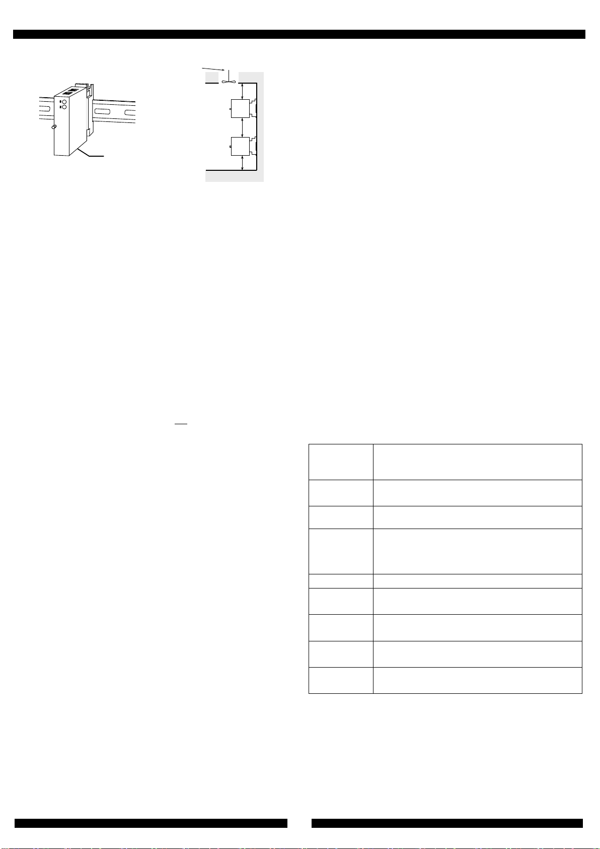
■The instrument should be installed as shown in the sketch below
namely, in such a position as the front panel label can be
readable in the right direction.
■For effective heat radiation, ample space (at least 100mm)
should be allowed at the top and the bottom of the units.
Also when the units are installed in multiple stacks, the space
between each stack should be at least 130mm.
Disregard of this clause may cause fatal
harm of serious bodily injury due to or
electric shock.
Disregard of this clause may cause bodily
harm or damages to nearby objects due to
electric shock or other accidental
happenings.
■
For wiring to the terminal block, make sure that the power is
turned OFF. Otherwise, electric shock may be caused.
■Do not break up, do not give any modification to modules, and do
not replace Power fuse at user’ side. Otherwise, fire or electric
shock may be caused.
■In case any foreign matters(metal chip, water, liquid, etc.)
penetrate inside modules, immediately remove the power wiring
and contact Shimaden or its distributor.
■When Main Unit is intended for use in the equipment for
transportation, communication, power-generation control and
medical care which require higher reliability and safety
characteristics. A special consideration should be taken in safety
designing for preventing malfunction of such an equipment as a
whole system.
■
Do not operate the instrument such an environment as
Flammable gases or dusts are present. Otherwise, explosion may
be caused.
■Avoid the installation of the instruments in the vicinity of any
combustibles.
■Because no power switch is provided on the instrument, the power
supply of the instrument cannot be turned OFF on the instrument
side. So, be sure to install a power shut-down breaker in the power
source of the instrument, and place the breaker close to the
instrument for the convenience of operation. And the breaker should
be marked as “disconnecting device” for the instruments.
■
Check out that the power supply voltage, input signal value and
terminal location conform to the published specifications of the
instrument(s). An operation under conditions outside the
specifications, heating up or burn out of the instrument(s) may
result.
■Avoid using the instrument(s) in such a place as the ambient
temperature fluctuates rapidly to cause condensation.
■Avoid operation or storage in such locations as corrosive gases are
present or splash of any chemical is feared.
■The units are hot-swappable, but this operation should be avoided
as for as possible.
■For the sake of safety, the installation and wiring should be taken
care of by fully-knowledgeable and well experienced persons.
!
WARNING
CAUTION
!
!
WARNING
CAUTION
!
User’s Manual Thin/Plug-In Alarm Setter CP3705
.
2
Bot t om
130mm mi ni mum
Cool i ng Fan
or Vent
100mm mi ni mum
100mm mi ni mum
On wiring:
■Connections to the instruments should be made to the terminal
block. For assignment of the terminal block, refer to section 6.
Screwing Torque: 0.8-1[N・m] (recommendable)
■Lead wire shall be twisted conductor with enough flexibility.
Nominal cross-sectional area of leadwire conductor: 0.5 to
2.0mm2 (recommendable).
■The connection of the lead wire to the terminal block shall be
made with insulated crimp terminals attached on an end of the
wire. Without the insulation, short-circuit or electric shock may
occur. The crimp terminal of 0.7-1.0mm thickness is
recommended.
Only up to 2 crimp terminals can be connected to 1 (one)
terminal screw.
※In this case, the thickness of the crimp terminal should be
smaller than 0.8mm.
To satisfy the performance of instrument(s)
■In order to lessen the influence of noise etc, the input/output
wire and power supply wire should not be used in a same
bundle or same conduit. They should be installed separately
with the minimum distance of 200mm.
■Avoid wiring of signal lines in the vicinity of such equipment as
electric motors, large scale transmitters, etc. , generating
magnetic field or electromagnetic wave. If inevitable, anti-noise
measure such as employment of shielded wire shall be
indispensable.
■At least 30 minutes of warm-up is required before operation.
■Any sensor or equipment to be connected to the instruments
should be selected in consideration of the input/output
impedance of the same (For the detailed specifications of the
unit, refer to section 4 or the description in URL:
http://www.shimaden.co.jp/).
Special note for CE marking
■The instrument is designed to conform EMC Directive and Low
Voltage Directive listed below;
EMC Directive (2004/108/EC)
Standard conformity EN61326-1 Class A
Low Voltage Directive (2006/95/EC)
Standard conformity EN61010-1/IEC61010-1
Installation category Ⅱ
Pollution degree 2
■The instruments should be install in a control panel.
■The instrument maintains basic insulation between input and
output, output and GND. Prior to installation, check that the
insulation class of the instrument satisfies system
requirements.
■When the instrument is installed in a control panel, the
measures to be taken for CE marking conformity may vary with
the type of devices connected, wiring to the instrument(s) or
structure of the control panel, etc. Therefore, check the control
panel as a whole to conform to CE marking regulations.
4. About the product
CP3705 compares DC input signal with two set points setting with
rotary switch of front panel of unit, and outputs the relay contact
signal.
Features
■Each trip point is set separately with rotary switches on front
panel. Setting Range: 0-99% (in steps of 1%)
■The contact part of unit and socket is gold-plated
(0.2μm) to ensure reliability and long-term stability.
■High Dielectric Strength of 2000VAC across Input-Output-
Power input-Ground
■The power unit can deliver AC power ranging from 85 to 264V
steplessly without switching to effectively meet varied power
requirements.
■Plug-in type for better maintainability
■Drop-proof terminal screws for ease and safety of installation
■Fuse installed in power line as standard attachment
■Anti-humidity coating on PCB for improved environmental
protection.
Specifications
Input
Resistance
Voltage input: 1MΩ min.
(1MΩ minimum without power)
Current input: 250Ω
Allowable
Input Voltage
Voltage input: 30VDC max. continuous
Current input: 40mADC max. continuous
Output Signal
Two independent type C relay contact closure
signals
Trip point
Setting: Setting with Rotary switch of front panel
Range: 0-99% set by 1% step
Stability: ±0.5% of span
Hysteresis: 1.0%±0.3% of span
Monitor Lamp
Red LED lights when relay is activated.
Power
Failure Effect
COM-NC of each output turn ON.
Relay Action
Limitation
To be ready for action about 2sec after power-up.
Temperature
Characteristics ±0.15% of span @ 10℃variation
Response
Time
150msec. max. 90% set @100% step input
Installing Position Installation Example

User’s Manual Thin/Plug-In Alarm Setter CP3705
.
3
5. Outer Dimensions and Terminal Signal Assignment
6. Connection Diagram
7. Connection to terminals
The following measures should be taken prior to the connection.
8. Output Connection
When any Inductive load, such as electric motor, etc. is to be
connected, be sure to connect a protection circuit for the relay
contact.
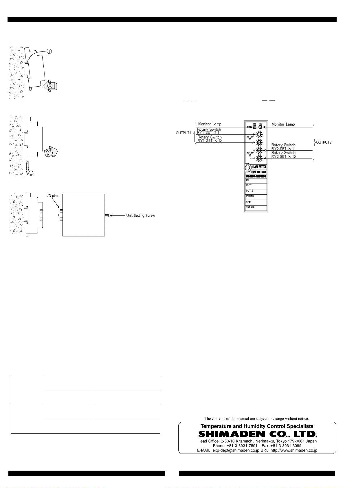
9. Power Line Connection
The terminal for power supply connection, pin number ①and
②, are covered with plastic plate for safety. (Refer to the sketch
(1).)
Lift the plastic cover plate and connect the power line to the
terminals. (Refer to the sketch (2).)
Return the cover plate to the original position. (Refer to the
sketch (3).)
(1) (2) (3)
45
12
P/+ N/-
45
45
Ter mi nal Cover
For the sake of safety, the wiring work should be performed with no
power supplied to the instrument. After wiring, check that all
terminal screws are securely fastened.
Insulation
Resistance
100MΩ min.
(
@500V DC
)
Across Input, Output-1, Output-
2, Power Supply
and Ground, mutually
Dielectric
Strength
Input/ Out-1/Out-2/ [Power Supply, Ground]:
2000VAC for 1 minute (cutoff current: 0.5mA)
Power Supply/ Ground:
2000VAC for 1minute (cutoff current: 5mA)
Relay
Contact
Rated Load: 5A 125VAC, 5A 30VDC
Maximum Voltage: 250VAC, 30VDC
Maximum Current: 5A(N.O.) / 3A(N.C.)
Electrical Life Span: 5A 250VAC(N.O.) 50k times
Frequency 1800 times/h
5A 30VDC(N.O.) 100k times
Frequency 1800 times/h
Physical Life Span: 5,000,000 times
Frequency 18000 times/h
Relay Response time: 3msec.
Surge
Withstand
Capability
Tested for ANSI/IEEE C37.90.1-1989
Storage
Temperature
-10 to +60°C
①Loosen the terminal screw.
②Insert tip of a screw driver bit
under the washer and push it
up to make ample room to
receive cable
Example of
AC power connection
Example of
DC power connection
Protection Circuit
(Barrister, CR circuit, etc.)
Protection Circuit
(Diode, Barrister CR circuit,
etc.)
POWER
SUPPLY
P(+)
N(-)
OUTPUT1
OUTPUT2
GND
+
-
INPUT
Terminal
No
8
10
11
7
9
6
5
4
2
1
COM
NO
NC
COM
NO
NC
Inductive
Load
COM
NO
NC
Inductive
Load
COM
NO
NC
User’s Manual Thin/Plug-In Alarm Setter CP3705
.
4
10. Mounting and Demounting
Mounting Terminal Block Socket
Demounting Terminal Block Socket
Installation to socket / Removal from socket
Installation to socket
①First, identify the top and the bottom of the unit and insert I/O pins
straight into corresponding pin slots(receptacles) on the socket.
②Tighten the set screw to fix the unit firmly on position.
Removal from socket
②Loosen the set screw.
②Pull out the unit carefully not to bend I/O pins.
11. Trip point Setting
Trip point is set by rotary switch at front panel of unit.
Refer to the following table, rotate the rotary switch by driver, etc.
and set trip point.
※Note for trip point setting
Set trip point without power supply.
When operating the rotary switch for limit value setting special
care should be taken to confirm ”clicking” the dial indicator stay in
between (on the halfway to) the desired right setting positions.
OUTPUT-1
RY1-SET×10 Place of ten of set point
(%) for input span
RY1-SET×1
Place of one of set point
(%) for input span
OUTPUT-2
RY2-SET×10
Place of ten of set point
(%) for input span
RY2-SET×1
Place of one of set point
(%) for input span
Ex.) When input signal is 0-5V and trip point of output-1 is set 4V
and trip point of output-2 is set 2.25V:
Since 4V is 80% of input span 5V, set RY1-SET×10 to 8 and
RY1-SET×1 to 0.
Since 2.25V is 45% of input span 5V, set RY2-SET×10 to 4 and
RY2-SET×1 to 5.
12. Maintenance
Checking of the adjustment and calibration in every 2 years is
recommended to secure accurate operation.
13. Warranty
WARRANTY
Shimaden's hardware products are warranted against defects in
materials and workmanship for a period of seven (7) year after the
date of shipment. Shimaden shall, at its option, either repair or
replace hardware products that prove to be defective, if Shimaden
receives notice of such defects during the warranty period.
Shimaden does not warrant that the operation of the hardware shall
be uninterrupted or error free. No other warranty is expressed or
implied. Shimaden specifically disclaims the implied warranties of
merchantability and fitness for a particular purpose.
LIMITATION OF LIABILITY
The warranty and remedies set forth above are in lieu of all other
warranties expressed or implied, oral or written, either in fact or by
operation of law, statutory or otherwise. Shimaden neither
assumes nor authorizes any other liability in connection with the
sales, installation, or use of its products. In no event shall
Shimaden be liable for direct, indirect, special, incidental, or
consequential damages (including loss of profits) of any kind arising
out the sale, installation or use of its products.
Hook the upper edge of the cavity on
the rear of the socket at the upper
blade of the rail ①, then push the
lower part of the socket against the
lower blade of the rail so as to make
the slide clamp engaged firmly with
the rail.
Push the slide clamp downward with a
screw driver bit or the like ①, and pull
the lower part of the socket toward
you ②.
80%
│└Set RY1-SET×1 to 0.
│
└
Set RY1-SET
×
10 to 8.
45%
│└Set RY2-SET×1 to 5.
│
└
Set RY2-SET
×
10 to 4.
Popular Security System manuals by other brands


Pilz
Pilz PSEN ml b 1.1 operating manual

Clas Ohlson
Clas Ohlson SST-10 user manual

SVAT
SVAT ClearVu 1202 instruction manual

PPP Taking Care
PPP Taking Care Personal Alarm Setup & user guide

DSC
DSC PTD1610-SCW Installation instructions and operators manual

DirecTV
DirecTV LifeShield Home Security Upgrade manual

Swann
Swann DVRx-2500 Setup guide

Bosch
Bosch FLM-420-RLE-S installation guide

Abra
Abra Kit-ABRA-101 quick start guide

Perenio
Perenio PEKIT01 quick start guide

Fike
Fike TwinflexPro2 conventional Expansion Card Installation and maintenance instructions

Star Headlight & Lantern
Star Headlight & Lantern Star X FIRE 200A Series manual