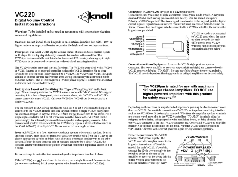
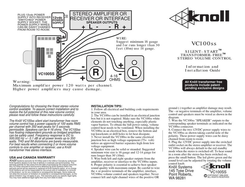
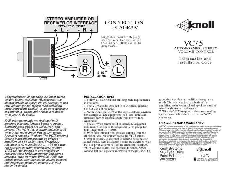
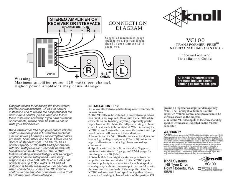
ground (-) together as amplifier damage may result.
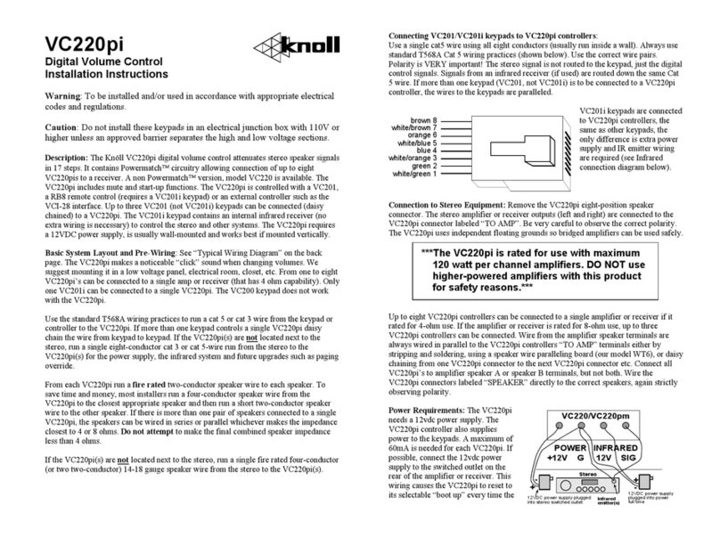
The - or negative terminals of the amplifier, volume
control and speakers must be wired as shown in the
diagram.
7. Wire the VC100sp "SPEAKER" outputs to the
corresponding speaker terminals as indicated on the
VC100sp connector.
8. Connect the two 12VDC power supply wires to
the VC100sp as shown taking careful note of the
polarity. These power supply wires can be daisy
chained from room to room.
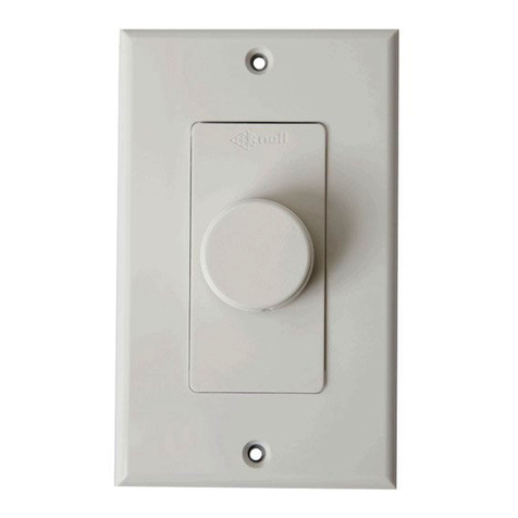
9. Plug the 12VDC power supply into the switched
outlet socket on the stereo amplifier or receiver. The
VC100sp will always default to the red standby
mode when the stereo is switched off. To hear sound
in a room after the stereo has been switched on,
press the small button. The led glows green and the
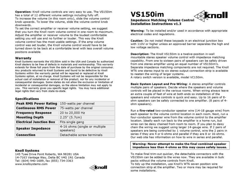
sound level can be adjusted by rotating the volume
control knob.
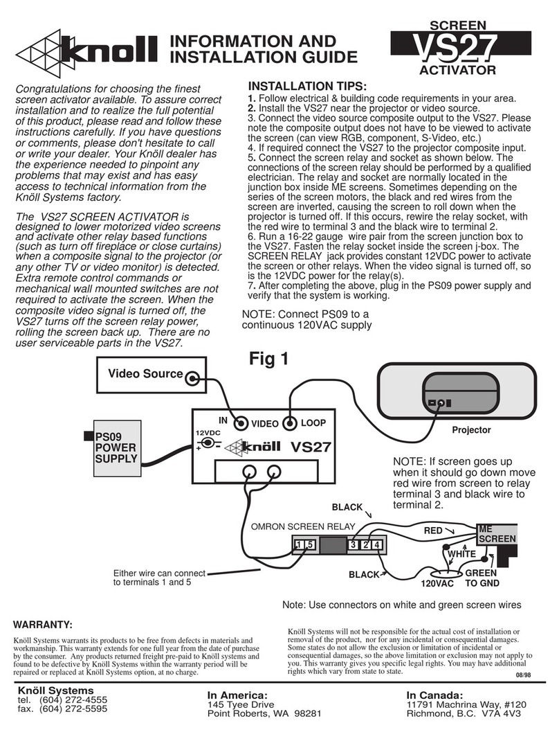
INSTALLATION TIPS:
1. Follow all electrical and building code requirements
in your area.
2. The VC100sp can be installed in an electrical junction
box but it is not required. Make sure the VC100sp white
elements do not touching anything, especially plastic
vapor barriers. To obtain the full power rating, volume
control heat needs to be ventilated. When installing the
VC100sp in an electrical box, remove the bottom and
top knockouts or drill holes to let heat dissipate.
3. Never install the VC100sp in the same electrical
junction box as high voltage equipment (75+ volt)
unless an approved barrier separates high from low
voltage equipment.
4. Speaker wire can be solid or stranded. Suggested
minimum wire size is 16 gauge and 12-14 gauge for
runs longer than 30' (10m).
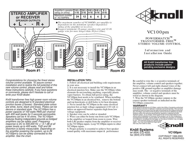
5. Wire left and right speaker outputs from the amplifier,
receiver or interface to the VC100sp inputs. VC100sp
inputs can be daisy chained to other VC100sp’s.
6. Proper polarity is essential to achieve best speaker
sound quality with maximum output. Be careful to wire
the + or positive terminals of the amplifier, interface,
VC100sp volume control and speakers together. Never
connect left and right channel wires of the positive OR
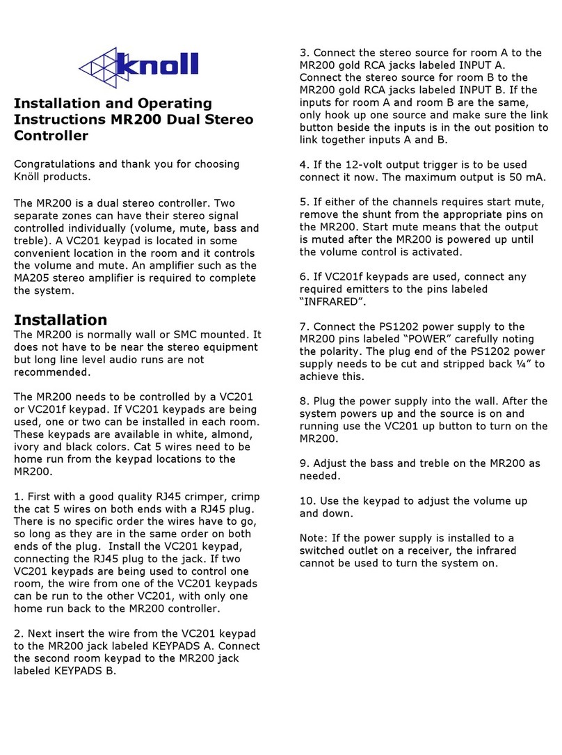
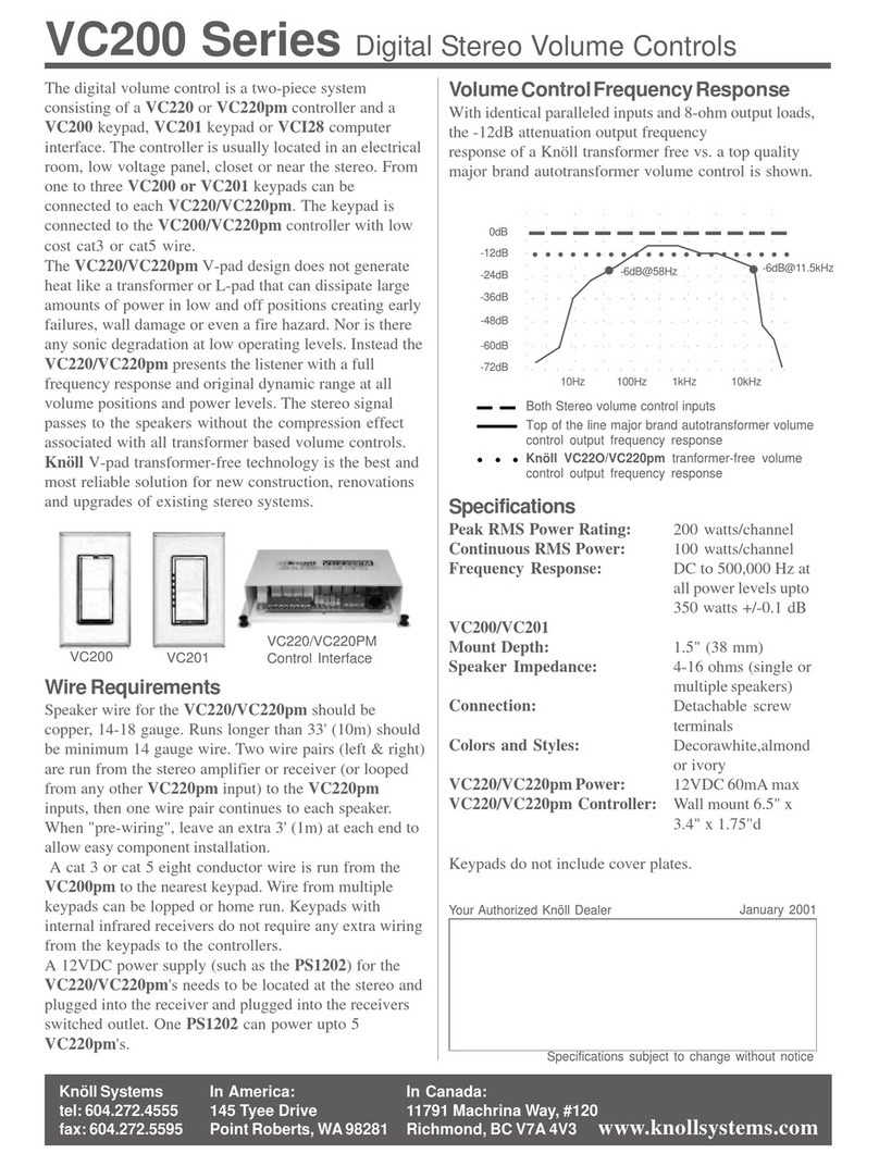
Congratulations for choosing the finest stereo volume
control available. To assure correct installation and to
realize the full potential of this new volume control,
please read and follow these instructions carefully.
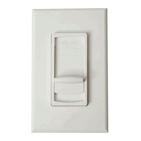
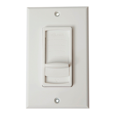
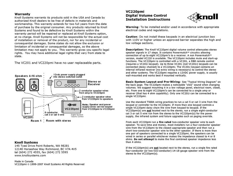
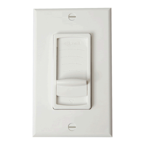
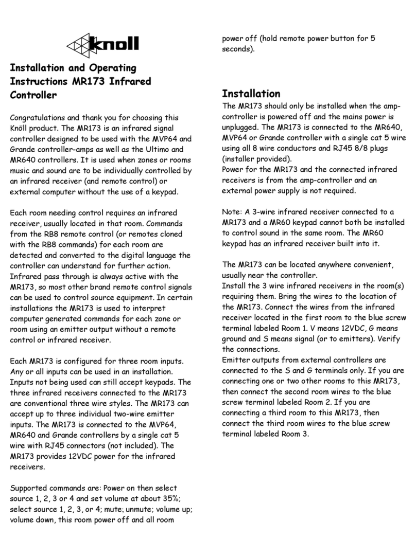
The Knöll VC100sp silent start transformer free room
volume control has a power capacity of 100 watts RMS
per channel with 350 watt peaks for 5 seconds
permissible. Speakers can be 4-16 ohms. The VC100sp
has floating independent grounds so bridged amplifiers
can be safely used. Frequency response is DC to
500,000 Hz +/- 0.1 dB at all power levels up to 350
watts. THD and IM distortions are barely measurable.
The VC100sp has an POWERMATCH automatic
impedence matching system built in allowing up to six
or more POWERMATCH volume controls to be
connected to one amplifier without danger of shutdown.
COPYRIGHT 1996-2002
ALL RIGHTS RESERVED
C
Knöll Systems
145 Tyee Drive
Point Roberts,
WA 98281
USA and CANADA WARRANTY
Knöll Systems warrants its VC100sp sold in the USA or Canada by authorized
Knöll Systems dealers to be free of defects in materials and workmanship. This
warranty extends for three years from the date of purchase by the original consumer.
Any VC100sp returned to and found to defective by Knöll Systems within the
warranty period will be repaired or replaced at Knöll Systems option, at no charge.
Knöll Systems will not be responsible for the actual cost of installation or removal
of the product, nor for any incidental or consequential damages. Some states do
not allow the exclusion or limitation of incidental or consequential damages, so the
above limitation may not apply to you. This warranty gives you specific legal rights.
You may have additional legal rights that vary from state to state. VC100sp
STEREO AMPLIFIER
or RECEIVER
SPEAKER OUTPUTS
+ L - - R +
L
R
VC100sp
L
R
+
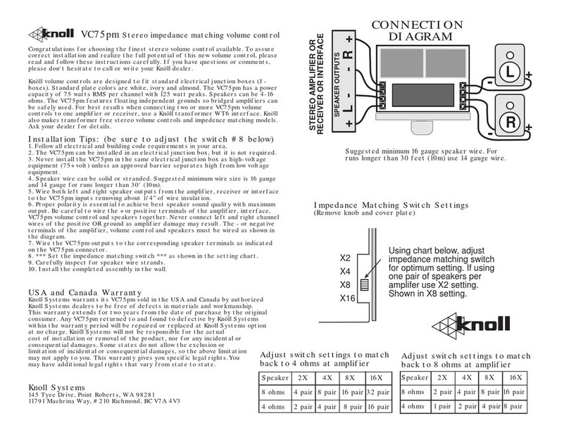
The maximum number of VC100sp's and VC100pm’s
per amplifer is dependent on the minimum speaker
impedence rating of the amplifier or receiver.
Suggest minimum 18 gauge speaker wire and 12-16
gauge wire for runs longer than 30 feet (10m).
Room #1 Room #2
VC100sp
L
R
Room #3
VC100sp +
+
+
+
+
-
--
--
-All Knöll transformer free
products include patent
pending exclusive designs
VC100sp
SILENT-START
POWERMATCH
TRANSFORMER-FREE
STEREO VOLUME CONTROL
Information and
Installation Guide
TM
TM
TM
Amplifier's speaker
rating (in ohms)
Maximum number
of VC100PM's
1-8 or
1-16 2-8 or
2-16 4-8 or
4-16 6-8 or
6-16 8 or
8-16
24 12 642
Switched
AC Outlet
PS1202


