Shimmer 3 User manual

Copyright © Shimmer Research 2013
Realtime Technologies Ltd IMU User Manual
All rights reserved Rev 1.1
1
ECG Respiration User Guide
Revision 1.1

Copyright © Shimmer 2018
Realtime Technologies Ltd ECG Respiration User Guide
All rights reserved Rev 1.1
1
Legal Notices and Disclaimer
Redistribution IS permitted provided that the following conditions are met:
Redistributions must retain the copyright notice, and the following disclaimer. Redistributions in electronic form
must reproduce the above copyright notice, this list of conditions and the following disclaimer in the
documentation and/or other materials provided with the document.
Neither the name of Shimmer Research, or Realtime Technologies Ltd. nor the names of its contributors may
be used to endorse or promote products derived from this document without specific prior written permission.
THIS DOCUMENT IS PROVIDED BY THE COPYRIGHT HOLDERS AND CONTRIBUTORS "AS IS" AND
ANY EXPRESS OR IMPLIED WARRANTIES, INCLUDING, BUT NOT LIMITED TO, THE IMPLIED
WARRANTIES OF MERCHANTABILITY AND FITNESS FOR A PARTICULAR PURPOSE ARE DISCLAIMED.
IN NO EVENT SHALL THE COPYRIGHT OWNER OR CONTRIBUTORS BE LIABLE FOR ANY DIRECT,
INDIRECT, INCIDENTAL, SPECIAL, EXEMPLARY, OR CONSEQUENTIAL DAMAGES (INCLUDING, BUT
NOT LIMITED TO, PROCUREMENT OF SUBSTITUTE GOODS OR SERVICES; LOSS OF USE, DATA, OR
PROFITS; OR BUSINESS INTERRUPTION) HOWEVER CAUSED AND ON ANY THEORY OF LIABILITY,
WHETHER IN CONTRACT, STRICT LIABILITY, OR TORT (INCLUDING NEGLIGENCE OR OTHERWISE)
ARISING IN ANY WAY OUT OF THE USE OF THIS DOCUMENT, EVEN IF ADVISED OF THE
POSSIBILITY OF SUCH DAMAGE.

Copyright © Shimmer 2018
Realtime Technologies Ltd ECG Respiration User Guide
All rights reserved Rev 1.1
2
Table of Contents
1. Introduction.............................................................................................................................. 3
2. General Information ................................................................................................................. 4
2.1. Safety Information ............................................................................................................. 4
2.2. Pre-Requisites.................................................................................................................... 4
2.3. ECG Unit Specification Overview ........................................................................................ 4
3. Electrode Placement ................................................................................................................. 5
3.1. Preparation........................................................................................................................ 5
3.2. Recommended Placement ................................................................................................. 5
4. Configuration ............................................................................................................................ 8
4.1. Default configuration ......................................................................................................... 8
4.2. Advanced Configuration..................................................................................................... 9
5. Example with post-processing................................................................................................. 11
6. References .............................................................................................................................. 13
7. Appendices ............................................................................................................................. 14
7.1. ExG configuration bytes ................................................................................................... 14

Copyright © Shimmer 2018
Realtime Technologies Ltd ECG Respiration User Guide
All rights reserved Rev 1.1
3
1. Introduction
The Shimmer3 ECG unit can be configured to measure respiration. This document provides
recommendations regarding electrode placement, configuration settings for respiration detection,
as well as an illustration of the signals that can be achieved from the device before and after
post-processing.
The respiration detection method used, is called "impedance pneumography". The Shimmer3 ECG
unit measures the impedance across the chest, using adhesive ECG electrodes. During the
inhalation/exhalation phases, this impedance increases/decreases respectively. The impedance
change is correlated to the volume of air that is inhaled [1].

Copyright © Shimmer 2018
Realtime Technologies Ltd ECG Respiration User Guide
All rights reserved Rev 1.1
4
2. General Information
2.1. Safety Information
As a precaution it is important to note that the ECG leads are not to be applied to the subject's body
while the unit is in a USB dock or multi-charger.
2.2. Pre-Requisites
A compatible Shimmer3 ECG unit programmed with up-to-date firmware.
-The Shimmer's firmware can be updated using our Consensys application - available
for download from www.shimmersensing.com.
-In order to check if respiration detection is supported on your Shimmer3 ECG unit,
please use Consensys and, with your Shimmer unit docked, refer to the "Expansion"
board information shown on-screen. If the expansion board appears as
"ECG/EMG/Respiration", respiration mode is supported.
Five DIN snap leads.
-9-inch and 18-inch leads are shipped with ECG Development Kits.
-Replacements can be purchased from www.shimmersensing.com.
Surface ECG electrodes.
-Disposable electrodes are shipped with the ECG Development Kit.
-For replacements, see www.shimmersensing.com. Alternatively, the Covidien
Kendall Disposable Surface EMG/ECG/EKG electrodes 1" (24mm) or Covidien Kendall
Disposable Surface EMG/ECG/EKG electrodes 1 3/8" (35mm), available on www.bio-
medical.com with product codes 'BRD H124SG' and 'BRD H135SG', respectively, and
the Ambu Blue Sensor T electrodes, available from various suppliers, are all suitable
options and have been validated for use with Shimmer equipment.
2.3. ECG Unit Specification Overview
The Shimmer3 ECG unit contains two ADS1292R chips from Texas Instruments. Throughout
documentation and software applications these are referred to a 'Chip1' and 'Chip2'. The respiration
circuitry is connected to Chip2 [2].
For detailed specifications of the Shimmer3 ECG unit or for more detail on the standard electrode
placement for ECG measurement, please refer to the Shimmer3 ECG User Guide.

Copyright © Shimmer 2018
Realtime Technologies Ltd ECG Respiration User Guide
All rights reserved Rev 1.1
5
3. Electrode Placement
3.1. Preparation
Prepare the skin by cleaning with an alcohol wipe or similar.
3.2. Recommended Placement
To detect respiration, the Shimmer3 ECG unit measures the impedance across the chest using three
electrode connections. The respiration detection circuitry is hard-wired to the RA (white) and LA
(black) inputs. In addition, the RL (green) input serves as reference.
The optimal electrode placement for respiration detection is two locations across the chest whereby
the Shimmer can measure the largest range of chest activity due to respiration (i.e., the maximum
change in impedance due to inhalation/exhalation). In this guide, we recommend the top of the mid-
axillary line on either side of the chest. Other locations can also be used [3]. Figure 3-1 provides a
side view of the axillary lines.
Figure 3-1 Axillary lines
Copyright © Shimmer 2018
Realtime Technologies Ltd ECG Respiration User Guide
All rights reserved Rev 1.1
6
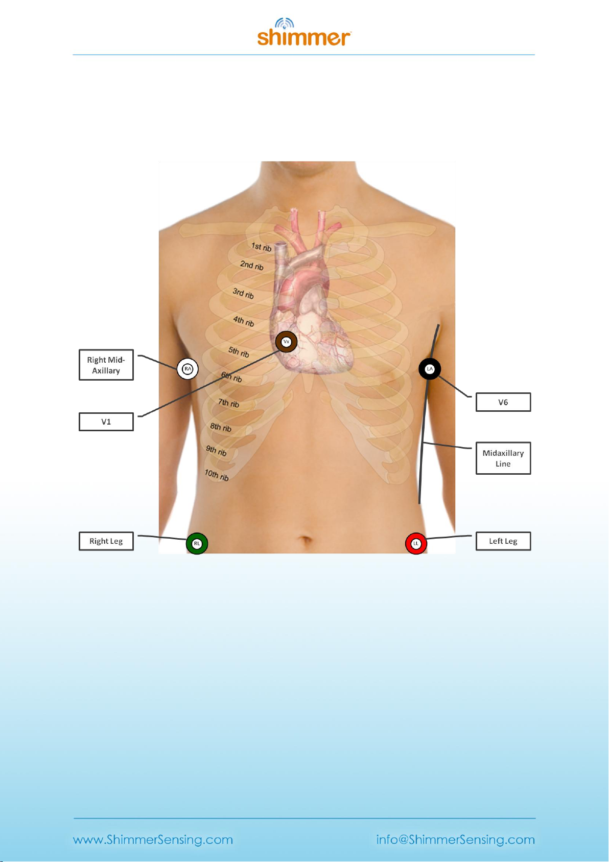
Figure 3-2 shows a recommended electrode placement layout on the body. The reference electrode,
RL (green), input should be placed on the top of the right leg. The LA (black) electrode should be
placed in the "V6" ECG electrode position (i.e., on the top of the mid-axillary line, on the left side of
the body, at the sixth inter-costal space). The RA (white) electrode should be placed at the same
location on the right-hand side of the body.
Figure 3-2 Recommended electrode placement
Although inputs LL (red) and Vx (brown) are not required for respiration detection, both inputs can
be used as additional ECG channels. If this these are in use, it is recommended to connect these to
the typical locations used for most clinical ECG electrode placements; the LL (red) input at the top of
the right leg and the Vx (brown) input at the standard "V1" ECG electrode position (i.e., at the fourth
inter-costal space, to the right of the sternum).
Note: In case Vx or LL are not connected to the body, make sure there is no electrode cable
connected to the corresponding input on the Shimmer3 ECG unit as this can introduce additional
noise in the system.

Copyright © Shimmer 2018
Realtime Technologies Ltd ECG Respiration User Guide
All rights reserved Rev 1.1
7
Table 3-1 gives an overview of the input connectors and the recommended electrode positions for
achieving the best respiration signal quality.
Table 3-1 Input connectors and electrode positions
Input
Electrode Position
Mid-Axillary line - right-hand side
Mid-Axillary line - left-hand side ("V6")
Right Leg
Left Leg (Optional electrode)
V1 (Optional electrode)

Copyright © Shimmer 2018
Realtime Technologies Ltd ECG Respiration User Guide
All rights reserved Rev 1.1
8
4. Configuration
4.1. Default configuration
This section describes how to enable respiration detection with default settings using our Consensys
software. Refer to section 4.2 for advanced configuration when using software other than Consensys
or non-default settings.
Figure 4-1 shows the configuration menu that can be accessed through either MANAGE DEVICES or
LIVE DATA.
Figure 4-1 Default Respiration Detection configuration.
Steps to enable respiration detection:
1. Set a minimum sample rate of 204.8Hz.
2. Enable "Respiration".
3. Set the gain to 3.
4. Write the configuration.
For the default configuration the Respiration Detection Frequency is 32 kHz and Respiration
Detection Phase is 112.5°.
1
3
2
4

Copyright © Shimmer 2018
Realtime Technologies Ltd ECG Respiration User Guide
All rights reserved Rev 1.1
9
4.2. Advanced Configuration
This section describes how advanced configuration settings can be modified when the default
configuration is not suitable or when software other than Consensys is used (e.g., Shimmer
APIs/Instrument Drivers).
The Shimmer3 ECG unit contains two ADS1292R chips from Texas Instruments. These chips are fully
configurable in software by setting the byte values of their ExG Configuration registers - also called
"ExG Configuration Bytes" in Shimmer documentation [2]. The values of the ExG Configuration Bytes
can be changed in the Consensys "Advanced ECG/EMG" menu, which can be accessed by clicking on
the corresponding icon on the "ECG/EMG" configuration tile, see Figure 4-2.
Figure 4-2 Advanced ECG/EMG icon
The adjustable parameters for Respiration Detection are:
1. Respiration Detection Frequency; Bit 2 of register "RESP2"
2. Respiration Detection Phase; Bits[5:2] of register "RESP1"
3. Gain of Programmable Gain Amplifier (PGA); Bits[6:4] of registers "CH1SET" / "CH2SET"
These parameters can be changed by modifying the values of the ExG Configuration Bytes directly,
or by using the drop-down menus highlighted in Figure 4-3. The drop-down menu for the PGA gain
can be found on the "ECG/EMG" configuration tile, see Figure 4-1 or Figure 4-2. For background
information on the Respiration Detection signal, refer to [1].
For respiration detection the "Reference Electrode" needs to be set to "Fixed Potential", see Figure
4-3. (For non-Consensys users: Chip1 RLD_SENS = 0x20, Chip2 RLD_SENS = 0x00).

Copyright © Shimmer 2018
Realtime Technologies Ltd ECG Respiration User Guide
All rights reserved Rev 1.1
10
Figure 4-3 Advanced ECG/EMG menu
Respiration Advanced chip configuration bytes:
For respiration detection, the configuration bytes of the ADS1292R chips need to be configured as
per Figure 4-4 below. This allows both chips to be synchronized at the same sampling clock and also
reduces power consumption in SR47-4 and greater versions as a second internally generated clock
does not need to be enabled (saving ).
Figure 4-4 Chip configuration
The recommended combinations of settings provided by Texas Instruments are listed in Table 4-1.
Alternatively, the user can experiment with values other than the ones recommended. Refer to
section 7.1 for an overview of all possible values for the Respiration Detection Frequency and the
Respiration Detection Phase.
ExG Configuration Bytes

Copyright © Shimmer 2018
Realtime Technologies Ltd ECG Respiration User Guide
All rights reserved Rev 1.1
11
Respiration Detection Frequency
Gain
Respiration Detection Phase
32 kHz
3
112.5°
32 kHz
4
135°
64 kHz
2
135°
64 kHz
3
157°
Table 4-1 Settings recommended by Texas Instruments
5. Example with post-processing
When the respiration detection circuitry is enabled, a very small high-frequency current is injected
into the body of the test subject. This high-frequency current acts a carrier wave that is
amplitude-modulated by the low-frequency respiration signal, i.e., the signal of interest. The
modulated signal is automatically demodulated within the Shimmer and the resulting respiration
waveform is presented as an output channel from the Shimmer while streaming/logging, see page 3
of [1] for a block diagram of this concept. Since the ADS1292r chip does not contain a low-pass filter
in the signal path between the demodulated respiration signal and the AD-converter (as shown in
page 3 of [1]), unwanted high-frequency content is still present in the signals. Post-processing the
signals afterwards in software can isolate the low-frequency respiration and ECG signals.
In this example the recommended electrode placement and the default configuration settings (and a
sampling rate of 512Hz) are used. Respiration signals are capture from a person carrying out the
following actions:
1. breathing normally for almost 80 seconds
2. followed by three pronounced inhalations and exhalations
3. followed by another 30 seconds of normal breathing
4. followed by three pronounced inhalations and exhalations
Figure 5-1 shows the resulting respiration signal after the signal has been post-processed using a
low-pass filter.

Copyright © Shimmer 2018
Realtime Technologies Ltd ECG Respiration User Guide
All rights reserved Rev 1.1
12
Figure 5-1 Respiration signal
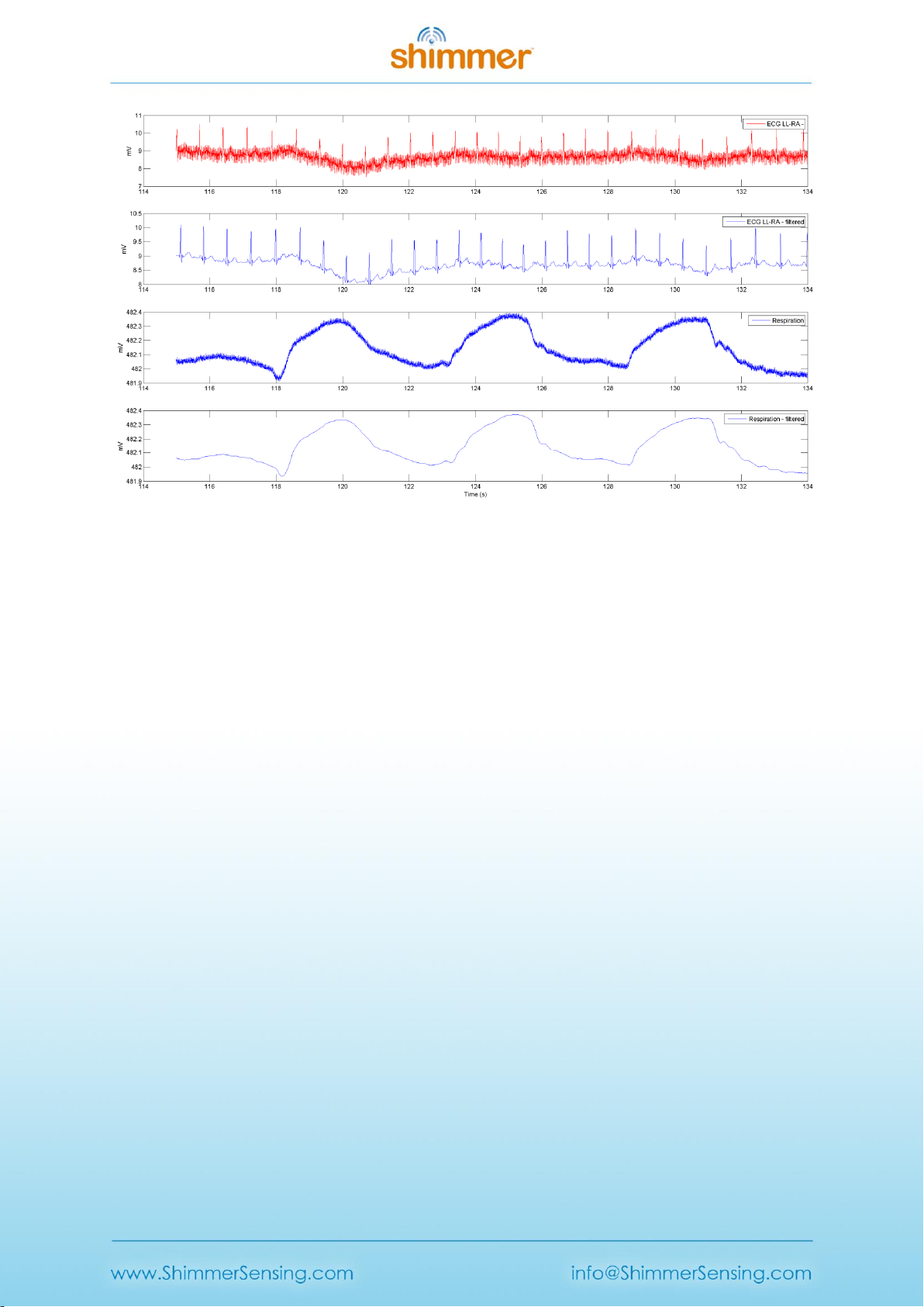
Figure 5-2 zooms in on the last three pronounced inhalations and exhalations, before (top) and after
filtering (bottom). The low-pass filter used to post-process the respiration signal is a low-pass
Blackman-Windowed Sinc-filter with 120 taps and a cut-off frequency of 2Hz.
Figure 5-2 Low-pass filtered respiration signal
Finally, Figure 5-3 also includes the ECG "LL-RA" signal; before and after filtering. The filter used is a
low-pass Blackman-Windowed Sinc-filter with 120 taps and a cut-off frequency of 30Hz.
Copyright © Shimmer 2018
Realtime Technologies Ltd ECG Respiration User Guide
All rights reserved Rev 1.1
13
Figure 5-3 ECG "LL-RA" and respiration
6. References
[1] Texas Instruments, “Respiration Rate Measurement Based on Impedance Pneumography,” 2011.
[2] Texas Instruments, “Low-Power, 2-Channel, 24-Bit Analog Front-End for Biopotential
Measurements,” 2012.
[3] G. B. Drummond, a F. Nimmo, and R. a Elton, “Thoracic impedance used for measuring chest
wall movement in postoperative patients.,” Br. J. Anaesth., vol. 77, no. 3, pp. 327–32, 1996.

Copyright © Shimmer 2018
Realtime Technologies Ltd ECG Respiration User Guide
All rights reserved Rev 1.1
14
7. Appendices
7.1. ExG configuration bytes
The relevant ADS1292R configuration bytes for respiration measurement are included in Table 7-1,
Table 7-2 and Table 7-3, for convenience. Please refer to [2] for more detailed information.
On/Off
Mask (hex)
Byte Value (hex)
Byte Value (dec)
On
0xC0
0xC0
192
Off
0xC0
0x00
0
Table 7-1 Respiration Detection mode - Chip2 "RESP1" register
Frequency
Mask (hex)
Byte Value (hex)
Byte Value (dec)
32 kHz
0x04
0x00
0
64 kHz
0x04
0x04
4
Table 7-2 Respiration Detection Frequency - Chip 2 "RESP2" register
Phase @ 32kHz
Phase @ 64kHz
Mask (hex)
Byte Value (hex)
Byte Value (dec)
0°
0°
0x3C
0x00
0
11.25°
22°
0x3C
0x04
4
22.5°
45°
0x3C
0x08
8
33.75°
67.5°
0x3C
0x0C
12
45°
90°
0x3C
0x10
16
56.25°
112.5°
0x3C
0x14
20
67.5°
135°
0x3C
0x18
24
78.75°
157.5°
0x3C
0x1C
28
90°
N/A
0x3C
0x20
32
101.25°
N/A
0x3C
0x24
36
112.5°
N/A
0x3C
0x28
40
123.75°
N/A
0x3C
0x2C
44
135°
N/A
0x3C
0x30
48
146.25°
N/A
0x3C
0x34
52
157.5°
N/A
0x3C
0x38
56
168.75°
N/A
0x3C
0x3C
60
Table 7-3 Respiration Detection Phase - Chip 2 "RESP1" register

Copyright © Shimmer 2018
Realtime Technologies Ltd ECG Respiration User Guide
All rights reserved Rev 1.1
15
Other manuals for 3
4
Table of contents
Other Shimmer Medical Equipment manuals


Popular Medical Equipment manuals by other brands


SOMNICS
SOMNICS iNAP One Instructions for use

PROVOX
PROVOX GuideWire manual

Direct Healthcare Group
Direct Healthcare Group RoMedic Carina350EM user manual

Prorelax
Prorelax SUPER DUO user manual

CUSTOM ULTRASONICS
CUSTOM ULTRASONICS 25000 Operator's manual

Ivoclar Vivadent
Ivoclar Vivadent UTS 3D operating instructions


