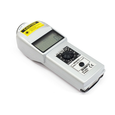
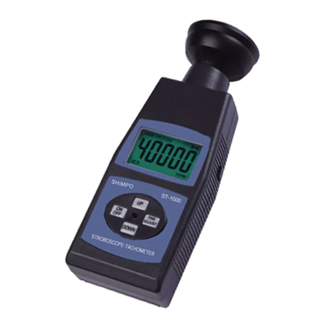
CONTROL PANEL
Revolutionsper
minute
0
OPERATING
PROCEDURES
Non-Contact Measurement
2.
Bringconeinto contactwiththe shaft. Apply onlyenough
1. Placeasmall pieceof reflectivetape pressureto avoid slippage.
(included) on the shaft or moving
3.
Press and hold the power switch. During engagement
element (disc, pulley, etc.) whose the displaywill reflecttheproperRPM while the unit RPM
speed is to be measured. If the will be flashing abovethe display digits.
element'ssurfaceis highlyreflective
it may need to be painted a darker
color in, order to ensure reliable
results. Ifthedistancetotheobject
is less than
5"
(127 mm), reflectivetabs (optional)should
be used instead of reflectivetape.
2.
Aimthe tachometer at the reflectivetape fromadistance
of
5"
(127 mm)to 14' (4.3 m).
3.
Press and hold the power switch for several seconds
(when power
button
is depressed, laser is
active) to observe the display
as
it changes according
to thespeed of theshaft or rotating element (as soon as
the laser hits the reflective tape, the unit will start to
indicate thespeed). Ifthe beam is "on target" a red dot
will flash inthe upper right corner of the display. If the
red dot is not flashing, the beam is "offtarget", and the
aim needs to be adjusted.
4. After observation is completed, retain the reading by
releasing the power switch (to turn off laser) before
removing the tachometer from its position. The last
reading is displayedfor a period of 10seconds and can
be extended any number of additional
5
minute
increments by pressingthe memory switch.
NOTE:
Whenswitchingfromthecontacttothenon-contactmode,
the unit RPM will show on the display and also
5
dashes
(---).
Pressthepower switch tocancelthedashes.
Contact Measurement
For bothRPM measurementsand non-RPM
measurements, screw the 200L adapter
(included)intothefront of thetachometer.
NOTE:
Hand tighteningis sufficient;
do
not
use excessivetorque when mounting
RPM
Measurement
1. Place rubber conetip onthe shaft of
theZOOLadapter. Make certainthat
the pin on the shaft is properly
aligned with the slot on the cone's
sleeve.
4. Releasethe power switch priortoremoval of tachometer
from rotating object to capturethe last reading.
5.
After release of the powerswitch, the last reading (with
a non-flashing RPM unit) will remain on the display and
in memory for
5
minutes, and can be extended any
number of additional
5
minute periods by pressingthe
memory switch.
Rate
(I
Length Measurement
1.
Attach
6"
masterwheel and select the
desired function using the selector
switch located just below the
LED
display.
2.
Press and hold the power switch;
while the wheel is turning and the
tachometer is measuringtheselected
function, the red dot in the upper
right corner of the display will beflashing.
3.
Release the power switch before disengaging the
tachometer in order to capturethe last reading.
4. After release of the power switch, the last, maximum,
and minimum readingswill be stored in memory for
5
minutes and can be extended any number of additional
5
minute periods by pressingthe memory switch.
NOTE:
Thememory will clear in
5
minutes after the release of
thepower switch.
For steps 1-4describedabove,
it
was assumed that theselector
switch was in the rate mode region. If the selector switch is
moved from the rate mode to the count mode (length), the
displaywill showtheselected function (m, ft, yd, or in) and also
5
dashes
(-----).
Press the power switch to cancel the dashes
andstart measuringthesamewayas wasdescribed above. Once
inthecounting mode, themeasurementcan bestopped at any
timeandthe last readingwill be retainedfor
5
minutes. There is
no maximum or minimum readingwhen inthe count (length)
mode.
1
I
LASER RAOIATI~IN
I
-
.
-
-
.. ..
.
.
-
.
.
..
,
-
.
.
1
DO
NOT STARE INTO BEAM
-.
A&
OUTPUT
c
lrn~
I
1
1'
WAVELENGTH
670nm
I
CLASS
I1
LASER PROllCT
2
INSTRUMENTS 11701 GlenlakeAvenue Itasca,IL 60143
.
phone: (800)237-7079.fax: (630) 924-0342 .www.shimpoinst.com


