Shimpo DT-361 User manual

Instruction manual
High Intensity LED Stroboscope Digital Tachometer
DT-361/365
Be sure to read before use.
Before use, please carefully read these safety precautions as well as instructions,
and follow them for proper use.
98585A
www.GlobalTestSupply.com
Find Quality Products Online at: sales@GlobalTestSupply.com

2
Safety Requirements Be sure to observe
Before operation, maintenance and inspection, please carefully read this instruction manual and
follow it for proper use. Please carefully read all information related to this unit's safety precautions
before use.
This instruction manual provides two grades of safety warnings: Danger and Caution.
Each of them is an important description related to safety. Be sure to follow them.
DANGER This indicates the possibility of fire, severe injury and even death if a user disregards the instruction
and operates the unit improperly.
CAUTION
This indicates a potential situation that could produce a minor injury or damage to material if it is
improperly handled.
However, depending on the circumstances, there could be a possibility that it may cause more
serious results. Be sure to follow them.
Protection categories are explained and separated by the following symbols
Not allowed -prohibited
Mandatory Must follow
DANGER
Do not use this product in an atmosphere
with risk of fire and/or explosion.
Failure to follow this could result in fire.
Do not look directly at the light emitting
section.
Failure to follow this could result in injury to the eyes.
CAUTION
Do not apply strong impact to the unit, or
drop it.
Failure to follow this could result in abnormal
operation.
Do not use and/or store the unit in the
following places.
•Where water may come in contact
•Where direct sunlight come in contact
•Where high humidity environment may be present
•Where dust, dirt, salt, and/or iron may be present
•Where oil, water, and/or chemicals come in contact
•Where a fire or explosion may exist or occur.
Never disassemble, repair, and remodel
the unit.
Failure to follow this could result in injury due to
abnormal operation.
Use the unit within the proper operating
temperature range (32 - 95F).
Failure to follow this could result in malfunction.
Wipe clean the unit with a soft dry cloth if it gets dirty.
Or immerse a cloth in water diluted neutral detergent,
wring it, and wipe clean the unit with it.
Do not use any volatile chemicals, such as benzene,
thinner, or alcohol.
Use the unit within the proper operating
humidity range (35 - 85%RH). (No
condensation)
Failure to follow this could result in malfunction.
Since continuously emitting light for long time
causes the unit's housing to be very hot, fix
the LED strobe using a tripod, etc. and use the
unit (avoid direct skin contact with the unit,
such as holding it by hand).
Failure to follow this could result in mild burns.
www.GlobalTestSupply.com
Find Quality Products Online at: sales@GlobalTestSupply.com

3
- Contents -
1 Overview 4
2 Before use 4
2.1 Checking accessories 4
2.2 Peel off the protection sheet 5
2.3 Charging (only for DT-365) 5
2.3.1 Charging method 5
2.3.2 Indication of low battery voltage 6
2.3.3 Battery replacement 6
3 Part names and functions 7
3.1 Main unit 7
3.2 Operation section 7
3.3 Display 8
3.3.1 Part names 8
3.3.2 Number display 8
3.3.3 Unit display 8
3.3.4 Emission setting display 8
3.3.5 Mode display 8
3.3.6 Memory number display 8
3.3.7 Charging lamp (only for DT-365) 8
4 Functions and operations 9
4.1 Power ON/OFF 9
4.2 Emission setting 10
4.3 Internal oscillation emission 11
4.3.1 Display of internal oscillation emission 11
4.3.2 Switching the modes 11
4.3.3 Switching the unit display 11
4.3.4 Emission count mode 12
4.3.4.1 Emission count setting 12
4.3.4.2 Changing the emission count (frequency) to double or half 13
4.3.5 Emission duration mod 14
4.3.6 Phase mode 15
4.4 External synchronous emission 16
4.4.1 Emission count mode 16
4.4.2 Emission duration mode 17
4.4.3 Phase mode 18
4.4.3.1 How to set the delay 19
4.5 Memory function 20
4.5.1 Saving each setting value 20
4.5.1.1 Saving on internal oscillation emission 21
4.5.1.2 Saving on external synchronous emission 22
4.5.1.3 Saving the setting value when the power is OFF 22
4.5.2 Reading out each setting value 23
4.5.2.1 Reading out on internal oscillation emission 23
4.5.2.2 Reading out on external synchronous emission 24
4.6 Function mode 25
4.6.1 Moving to the function mode 25
4.6.2 Measurement range setting (Function mode 1) 26
4.6.3 Trigger edge setting (Function mode 2) 27
4.6.4 Auto emission stop time setting (Function mode 3) 29
4.6.5 Input signal setting (Function mode 4) 30
4.7 External I/O connector 31
4.7.1 Specifications for external I/O connector and pin assignment 31
4.7.2 External pulse input 32
4.7.3 External trigger pulse output 32
5 Specifications 33
6 External dimensions 34
7 Trouble shooting 35
www.GlobalTestSupply.com
Find Quality Products Online at: sales@GlobalTestSupply.com

4
Overview1
A stroboscope tachometer is a measurement instrument to measure the speed (cycle) of rotating
objects that rotate at a constant speed, or moving objects that repeatedly operate at a constant
cycle. When the rotation (motion) cycle matches the flash cycle while the strobe flash is periodically
applied on a rotating or moving object, the rotating (moving) object image appears to stand still. This
stroboscope tachometer is non-contact and can be used to read the flash frequency when such a still
image appears. Also, a stroboscope can be used to make images of rotating or moving objects stand
still or slightly move in order to observe their appearances.
Main features
Wide-range measurement of 60 to120,000 fpm
Refer to 4.3.4.1 Emission count setting for details
Simply pressing the x2 or ÷2 key can change the emission count (frequency) to double or half
respectively
Refer to 4.3.4.2 Changing the emission count (frequency) to double or
half for details
The emission time (duty) can be changed by 0.1º within the range between 0.1º/ to 3.6º/ 360º
Refer to 4.3.5 flash duration mode
The emission timing (phase) can be adjusted
Refer to 4.3.6 Phase mode for details
The external I/O function is implemented which enables emission in synchronization with the external
pulse, and enables the pulse signal in synchronization with the strobe emission to be output.
Refer to 4.4 External synchronous emission for details
Before use2
Checking accessories2.1
Check that the three items in the table below are supplied.
DT-361 DT-365
Main unit
DT-361 x 1 DT-365 x 1
Connector
External signal I/O connector (8 pin) x 1
RM15WTP-8S(7)
Dedicated AC adapter x 1
Instruction manual
This document x 1 This document x 1
www.GlobalTestSupply.com
Find Quality Products Online at: sales@GlobalTestSupply.com

5
Peel off the protection sheet2.2
Peel off the protection sheet on the operation section.
Operation section
Peel off the (transparent)
protection sheet
Charging (only for DT-365)2.3
Be sure to charge the battery before initial use. Before charging, be sure to check that the power is
turned OFF.
Charging method2.3.1
Turn the power OFF and connect the supplied AC adapter's connector to the main unit. Next insert
the AC adapter's AC plug into an outlet. The battery lamp lights up and charging starts.
Charging is complete in approximately 2.5 hours. Then the battery charging lamp turns off.
* Be sure to use only the supplied AC adapter.
When the power is turned ON with the supplied AC adapter connected, charging ends and
operation starts.
* Note that operation and charging cannot be performed simultaneously.
Connect the supplied AC adapter
Note 1) Since the battery current is automatically shut off when charging is complete, there is no need
to worry about overcharging.
Note 2) When the power is turned ON during charging, charging is canceled and emission starts. When
the unit uses the AC adapter as its power source, it is not charged.
Note 3) To extend battery life and charging capacity, it is recommended to deplete the battery fully
before charging. ( LLLLLL is indicated on the number display)
Note 4) If the unit is charged immediately after long periods of usage at a high ambient temperature,
the temperature rise protection circuit will turn on and the charging lamp may not light up. In
that case, disconnect the AC adapter and let the unit cool. When the product temperature is
decreased, connect the AC adapter again to start charging.
Note 5) Never charge the unit under the following conditions.
Adapter of
another device
Charging near flammable materials
Using another AC adapter than supplied.
Oil
www.GlobalTestSupply.com
Find Quality Products Online at: sales@GlobalTestSupply.com

6
Indication of low battery voltage2.3.2
If the remaining battery power drops to near zero, the number display alternates between the
process setting and LLLLLL. However, operation can be performed even when the battery is in this
low condition.
If the remaining battery decreases further, the number display indicates only LLLLLL, which then
stops operation. Press the power switch and shut off the power immediately.
In either case, charge the unit according to the procedure in 2.3.1 Charging method .
•Indication of low battery voltage
Indicates alternately
•Indication of stopped operation
Battery replacement2.3.3
If the fully charged battery continually decreases, please replace it with the specified replacement
battery. Please contact your local dealer for details.
1. Remove 4 screws located on the bottom of DT-365 and take out the battery assembly.
2. Remove the screws on the connector and the battery supporter and replace with the new
battery.
3. Fix the new battery with the screws and connect the connector.
4. Install the new battery assembly to DT-365.
Connector Battery
Fix with the hole facing the front.
www.GlobalTestSupply.com
Find Quality Products Online at: sales@GlobalTestSupply.com

7
Part names and functions3
Main unit3.1
Super luminosity LED (18 lights)
Power switch
External I/O connector
Operation
section
* The image is for DT-365.
Operation section3.2
②
①
③
④
⑧
⑥
⑦
⑤
* The image is for DT-365.
No. Name Function description
①Power switch Turns the power ON/OFF.
②Dial Used to change the emission frequency or emission duration.
③MODE key
Each press of this key switches the number display in the following order: Emission
frequency (FPM), Emission duration, Emission delay duration (PHA), Emission
frequency (FPM)...
④
LOAD (SAVE) key
Reads the saved setting value.
Also, saves the current setting value by pressing and holding it.
⑤SIG key Switches the internal oscillation emission and external synchronous emission.
⑥UNIT key
Switches to indicate the emission time when the emission duration is indicated. When
the delay duration is indicated, each press of this key switches indication of the delay
time and angle.
⑦x2 key Each press of this key during on internal oscillation emission alters allows the
performance of emission by double the current set emission count (frequency).
⑧÷2 key Each press of this key during on internal operation mode drops the current emission by
half the count (frequency).
www.GlobalTestSupply.com
Find Quality Products Online at: sales@GlobalTestSupply.com

8
Display3.3 Part names3.3.1
Numerical display
Unit display
Mode display
Emission setting
display
Memory number display
Charging lamp (only for DT-365)
Number display3.3.2
•Indicates the setting value of the emission count (frequency) in internal oscillation emission mode.
•Indicates the external signal frequency in external synchronous emission mode.
•Each setting value is indicated in the function setting mode.
* For details about the function setting mode, refer to 4.6 Function mode.
Unit display3.3.3
Indicates the unit of the value on the number display.
Emission duration (angle)
Delay duration (phase)
Emission duration (time) Delay time
Emission setting display3.3.4
Indicates the emission setting.
Internal oscillation emission External synchronous emission
Mode display3.3.5
Indicates the mode on the number display.
Emission count mode Emission duration mode Phase mode
Memory number display3.3.6
Indicates the memory number on the number display.
When all the numbers go off the memory number 0 (free mode) is assigned and the previous
setting value is indicated.
Charging lamp (only for DT-365)3.3.7
Lights up while charging and goes off when charging is complete.
www.GlobalTestSupply.com
Find Quality Products Online at: sales@GlobalTestSupply.com

9
Functions and operations4
Power ON/OFF4.1
Press the power switch when the power is OFF to turn the power ON.
When the power is turned ON, the model is indicated, followed by internal oscillation emission or
external synchronous emission.
Operation Display
When the power is
OFF
Press the power
switch
The screen of internal oscillation
emission is indicated and emission
starts.
Internal oscillation emission
when the power was last OFF
External synchronous emission
when the power was last OFF The screen of external synchronous
emission is indicated and the unit
enters the standby mode for the
external signal.
* When DT-365 is used, the indication may go off immediately after the power is turned ON. In that case,
charge the unit because the remaining battery level is low. For details about charging, refer to 2.3
Charging.
Press the power switch when the power is ON to turn the power OFF, then the indication goes off.
Operation Display
When the power is ON
Press the power
switch
Indicated letters go off.
* When the power is turned ON, the following indication may be displayed.
The following is the error message showing EEPROM read failure. Press the x2 key to return to the normal
emission screen from the error message display.
Operation Display
Press the x2 key Returns to the normal
setting screen
Error display
EEPROM read failure
www.GlobalTestSupply.com
Find Quality Products Online at: sales@GlobalTestSupply.com

10
Emission setting4.2
Each press of the SIG key switches between internal oscillation emission and external synchronous
emission.
Operation Display
Each press switches
the emission settings
Internal oscillation emission External synchronous emission
www.GlobalTestSupply.com
Find Quality Products Online at: sales@GlobalTestSupply.com

11
Internal oscillation emission4.3 Display of internal oscillation emission4.3.1
Setting value
Mode display
Memory number
display
Display showing internal
oscillation emission
Switching the modes4.3.2
Each press of MODE key switches the setting display value to FPM (emission count mode), DUR
(emission duration mode), and PHA (phase mode).
Operation Display
Each press switches
the modes
Emission duration mode
Phase mode
Emission count mode
Switching the unit display4.3.3
While the UNIT key is pressed and held in the emission duration mode (DUR), the unit display is
switched from [º] to [μs].
Each press of the UNIT key in the phase mode (PHA) switches the unit display from [º] to [ms].
Button operation Display
Indicates time while
the key is being
pressed
•Emission duration mode (DUR)
Indicates angle Indicates time
Each press switches
the display
•Phase mode (PHA)
Indicates angle Indicates time
www.GlobalTestSupply.com
Find Quality Products Online at: sales@GlobalTestSupply.com

12
Emission count mode4.3.4
The emission count (frequency) can be set in the emission count mode (FPM).
Emission count setting4.3.4.1
Turn the dial to the CW direction to increase the emission count (frequency), and to the CCW
direction to decrease it. Turn the dial fast to change the setting value greatly and slowly to change
it slightly.
The emission count (frequency) you can set depends on the measurement range. For details about
the measurement range, refer to 4.6.2 Measurement range setting.
Press the MODE key to switch to the emission duration mode (DUR).
Operation Display
Increase/decrease
the emission count
(frequency)
Decrease Increase
CCW
CW
Press the key to
switch to the emission
duration mode Emission count mode Emission duration mode
www.GlobalTestSupply.com
Find Quality Products Online at: sales@GlobalTestSupply.com

13
Changing the emission count (frequency) to double or half4.3.4.2
The emission count (frequency) can be changed to double or half of the current setting value using
the key operation on internal oscillation emission.
1) To change the emission count (frequency) to double of the current setting value
Each press of the x2 key changes the emission count (frequency) to double of the current setting
value on internal oscillation emission.
Operation Display
Each press
increases the
emission count to
double
Emission count mode
1,500fpm
Emission count mode 3,000fpm Emission count mode 6,000fpm
* If the doubled emission count (frequency) goes beyond the value in the measurement range, the key
operation will be disabled.
The emission count (frequency) after change provides the value according to the setting display
resolution (for details about the setting display resolution, refer to 5 Specifications). For this reason,
after pressing the x2 key and doubling the emission count (frequency), the value may not be returned
to the initial value even by pressing the "÷2" key and halving it.
2) To change the emission count (frequency) to half of the current setting value
Each press of the "÷2" key changes the emission count (frequency) to half of the current setting
value on internal oscillation emission.
Operation Display
Each press
decreases the
emission count to
half
Emission count mode
1,500fpm
Emission count mode 750fpm Emission count mode 375fpm
* If the half of the emission count (frequency) goes below the value in the measurement range, the key
operation will be disabled.
The emission count (frequency) after change provides the value according to the setting display
resolution (for details about the setting display resolution, refer to 5 Specifications). For this reason,
after pressing the ÷2 key and halving the emission count (frequency), the value may not return to the
initial value even by pressing the x2 key and doubling it.
www.GlobalTestSupply.com
Find Quality Products Online at: sales@GlobalTestSupply.com

14
Emission duration mode4.3.5
The emission time (ratio) can be set by 0.1º within the range between 0.1º/ 360º and 3.6º/ 360º in
the emission duration mode (DUR). The emission time setting value shows the strobe emitting
time by angle while a rotating object rotates one revolution (360º).
While the “UNIT” key is being pressed, the value converted from the emission angle to time can be
checked.
A longer emission time increases the brightness, but a measured object appears to be moving.
Also, a shorter emission time decreases the brightness, but a measured object appears to stand
more still.
Adjust the appropriate emission time according to your application and conditions and use the unit.
Press the MODE key to switch to the phase mode (PHA).
Operation Display
Increase/decrease
the emission angle
Indicates the
emission time while
the key is being
pressed
Emission angle: Decreases Emission angle: Increases
Indicates the value converted
from the emission angle to time
Indicates the value converted
from the emission angle to time
CW
CCW
Press the key to
switch to the phase
mode Emission duration mode Phase mode
www.GlobalTestSupply.com
Find Quality Products Online at: sales@GlobalTestSupply.com

15
Phase mode4.3.6
When the rotation (motion) cycle of a measured object matches with the strobe flash cycle, the
measured object appears to stand still. To change the angle (position) to make the object stand
still, use the phase mode.
The phase can be changed by 0.1º using the dial within the range between 1º and 359º in the phase
mode (PHA).
Press the UNIT key to set the phase change by time. The phase can be changed by 1 ms within
the range between 0 ms and 999 ms (max.).
When time is used for setting, a longer time duration than the emission cycle cannot be set.
Press the MODE key to switch to the emission count mode (FPM).
Operation Display
Increase/decrease
the delay angle
Each press switches
the delay time
display
Delay angle: Decreases Delay angle: Increases
Delay time: Decreases Delay time: Increases
CCW
CW
CCW
CW
Press the key to
switch to the emission
count mode Phase mode Emission count mode
www.GlobalTestSupply.com
Find Quality Products Online at: sales@GlobalTestSupply.com

16
External synchronous emission4.4
External synchronous emission is the function to emit a strobe flash in synchronization with an
external pulse.
•To activate external synchronous emission mode, refer to 4.2 Emission setting.
•You can set which edge of the external pulse triggers the emission, the rising edge or falling edge.
Refer to 4.6.3 Trigger edge setting.
•Timing (delay) from the external pulse entry to strobe flash emission can be optionally set.
Emission count mode4.4.1
Measurement value of the emission count (frequency)
Indicates the external
synchronous emission
Mode display
Indicates the memory
number
* The external pulse frequency is measured per cycle and indicated (An averaging procedure is applied
every 200 ms to update the measurement value and indicate the latest one.)
If the external pulse cycle is beyond the specifications range, the following letters are indicated.
[Without the delay angle setting]
Measurable range 40 to 35,000
When the external input pulse
frequency goes below 40 fpm
When the external input pulse
frequency goes beyond 35,000 fpm
[With the delay angle setting]
Measurable range 60 to 10,000
When the external input pulse
frequency goes below 60 fpm
When the external input pulse
frequency goes beyond 10,000 fpm
Press the MODE key to switch to the emission duration mode (DUR).
Operation Display
Press the key to
switch to the emission
duration mode Emission count mode Emission duration mode
www.GlobalTestSupply.com
Find Quality Products Online at: sales@GlobalTestSupply.com

17
Emission duration mode4.4.2
The emission time (ratio) can be set by 0.1º within the range between 0.1º/ 360º and 3.6º/ 360º in
the emission duration mode (DUR). (The emission time setting value shows the strobe emitting
time by angle while a rotating object rotates one revolution (360º).)
While the “UNIT” key is being pressed, the value converted from the emission angle to time can be
checked.
A longer emission time increases the brightness, but a measured object appears to be moving.
Also, a shorter emission time decreases the brightness, but a measured object appears to stand
more still.
Adjust the appropriate emission time according to your application and conditions and use the unit.
Press the MODE key to switch to the phase mode (PHA).
* When the external synchronous signal has not been entered, [ _ _ _ _ _ _ ] and the emission time are
indicated alternately.
When the external synchronous signal has been entered, only the emission time is indicated.
Operation Display
Increase/decrease the
emission angle
Indicates the time
conversion value
while the key is being
pressed
Emission angle: Decreases Emission angle: Increases
Indicates the value converted
from the emission angle to time
Indicates the value converted
from the emission angle to time
CCW CW
Press the key to
switch to the phase
mode Emission duration mode Phase mode
www.GlobalTestSupply.com
Find Quality Products Online at: sales@GlobalTestSupply.com

18
Phase mode4.4.3
Delay emission can be set within the input signal range between 60 fpm and 10,000 fpm.
In the phase mode (PHA), the delay angle from the external pulse entry to strobe flash emission
can be changed by 0.1º using the dial within the range between 1º and 359º.
Press the UNIT key to set the phase change by time. The phase can be changed by 1 ms within
the range between 0 ms and 999 ms (max.).
When time is used for setting, a time longer than the emission cycle cannot be set.
Press the MODE key to switch to the emission count mode (FPM).
* When the external synchronous signal has not been entered, [ _ _ _ _ _ _ ] and the delay setting values
are indicated alternately.
When the external synchronous signal has been entered, only the delay setting value is indicated.
Operation Display
Increase/decrease
the delay angle
Each press switches
the delay time
display
Delay angle: Decreases Delay angle: Increases
Delay time: Decreases Delay time: Increases
CCW
CW
CCW
CW
Press the key to
switch to the phase
mode Phase mode Emission count mode
www.GlobalTestSupply.com
Find Quality Products Online at: sales@GlobalTestSupply.com

19
How to set the delay4.4.3.1
The delay angle from the pulse input to emission can be set by 0.1º within the range between 1º
and 359º by setting one cycle of the external pulse to 360º. Measure the external pulse frequency
per cycle, and calculate the delay angle based on the measured frequency to perform the delay
emission. Since a delay of approximately 30 μs always exists for the internal calculation, the actual
delay time is calculated as follows:
Delay setting angle × External pulse cycle + Approximately 30 μs
360°
[Example 1] When setting the input frequency to 10 Hz (600 fpm), trigger edge to rising, and
delay angle to 36º
External pulse
(Pulse entered from an
external device to DT-361/365)
Strobe emission
100ms(360º)
10ms(36º)
Frequency
calculation
Delay
emission
Frequency
calculation
100ms(360º)
10ms(36º)
Delay
emission
* When the delay unit is set to ms in the above example, the delay time can be set within the time range
of less than one cycle input pulse (0 ms to 99 ms).
•Since the delay angle is calculated based on the previously entered pulse cycle, if the external
pulse frequency changes, emission cannot be performed at a precise angle. Also, since the
external pulse cycle becomes shorter than the previous pulse cycle, if the next pulse is entered
before delay angle emission, the delay angle setting will be disabled, and emission is performed
simultaneously* with the external pulse.
•When the delay angle is set to 0º, emission is performed simultaneously with the external pulse.
* Since there is a delay caused by the internal calculation process, the strobe actually emits light in
approximately 30 μs after the external pulse is entered.
Turn the dial to the right to increase the delay angle setting value. Increasing the setting value from
359º will be 0º.
www.GlobalTestSupply.com
Find Quality Products Online at: sales@GlobalTestSupply.com

20
Memory function4.5
Each setting value can be saved and read out.
Saving each setting value4.5.1
This function is used to save each setting value.
There are two types of saving methods, one is to save a parameter by pressing and holding the
“LOAD(SAVE)” key, and the other is to save a setting value by turning the power OFF.
The number of data entries that can be set is five on internal oscillation emission and external
synchronous emission respectively when saving by the “LOAD(SAVE)” key, and one when saving
by power OFF.
Setting values that can be saved
Saving method Save a parameter using the
“LOAD(SAVE)” key Save when the power is turned OFF
Emission status when the value is saved
Internal
oscillation
emission
External
synchronous
emission
Internal
oscillation
emission
External
synchronous
emission
Memory number that can be saved 1 to 5 1 to 5 - -
Emission mode (INT/EXT) × × ○○
Setting mode (FPM/DUR/PHASE) ○○○○
Internal
oscillation
emission
(INT)
Emission frequency (FPM)
○×○○
Emission duration (DUR)
○×○○
Delay angle (PHASE) ○×○○
Delay time (PHASE) ○×○○
External
synchronous
emission
(EXT)
Emission duration (DUR)
×○○○
Delay angle (PHASE) × ○○○
Delay time (PHASE) × ○○○
www.GlobalTestSupply.com
Find Quality Products Online at: sales@GlobalTestSupply.com
This manual suits for next models
1
Table of contents
Other Shimpo Measuring Instrument manuals

Shimpo
Shimpo DT209X User manual

Shimpo
Shimpo DT-2100 User manual
Shimpo
Shimpo PT-120 User manual

Shimpo
Shimpo DT-326 User manual

Shimpo
Shimpo DT-5TG User manual

Shimpo
Shimpo DT-5TS User manual

Shimpo
Shimpo FG-7000 User manual
Shimpo
Shimpo DT-365E User manual
Shimpo
Shimpo FGV-0.5XY User manual
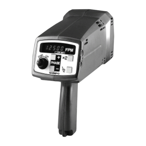
Shimpo
Shimpo DT-725 User manual
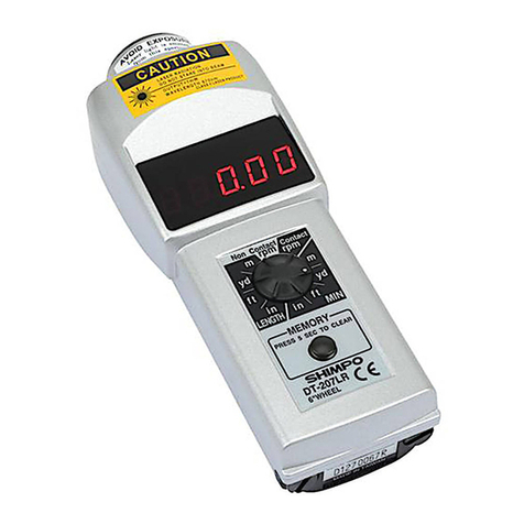
Shimpo
Shimpo DT-207L User manual
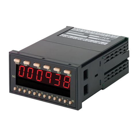
Shimpo
Shimpo DT-5TXR User manual

Shimpo
Shimpo CAG3000 User manual
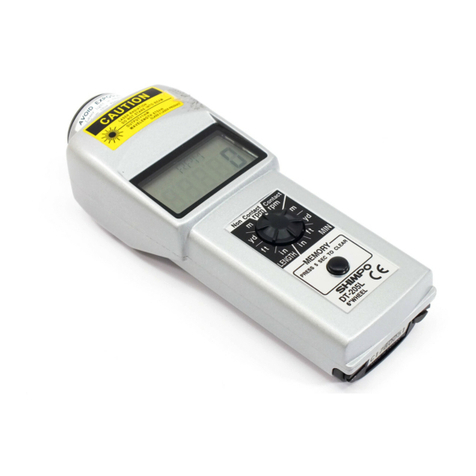
Shimpo
Shimpo DT-205L User manual
Shimpo
Shimpo FG-7000L-M-100 User manual

Shimpo
Shimpo DRI User manual

Shimpo
Shimpo DT-725 User manual
Shimpo
Shimpo CAG2000 User manual

Shimpo
Shimpo FGV-0.5XY User manual
Shimpo
Shimpo ST-1000 User manual


