Shindaiwa DGW300M User manual

OWNER
’
S AND OPERATOR
’
S MANUAL
Vertical, Water-Cooled 4-Cycle Diesel Engine
DGW300M/MY
X750-021 72 0
X750803-580 0
CAUTION
Do not operate the Generator/Welder, or any other appliance, before you
have read and understood the instructions for use and keep near for readily
use.


Introduction
Thank you for purchasing Shindaiwa Sound Proof Diesel Engine Generator & Welder.
•
This user manual was created to ensure the safe operation of this equipment.
Therefore, the manufacturer of this equipment strongly recommends that the user
follow the instructions herein, to avoid unnecessary accidents and repairs.
•
Please operate this equipment after thoroughly reviewing and understanding the
contents of this manual. Do not operate the equipment while under the influence of
alcohol, medication, or other drugs, or while fatigued.
•
Must be compliant with all applicable regulations for the area in which the equipment
is operated.
•
Please attach this manual and explain how to operate and have them read this
manual, if the equipment will be sub-leased.
•
Please store this manual near the equipment for easy reference. Replace damaged
or missing the manual with new manual from authorized distributor.
•
For service, contact the authorized distributor. Please be prepared to give them the
model name and serial number.
•
Observe the relevant environmental protection regulations when disposing of
equipment.
■Following convention will be used throughout the manual to indicate the
degree of cautions.
•
Even some of the items noted in『 Caution 』may lead to serious injuries.
Please read all item and follow all the safety guidelines.
Danger:Can cause serious injuries or death.
Caution:Can cause minor injuries or damage to the equipment or other
properties.
<Caution> :Other types of caution.

- 1 -
Table of Contents
1.
..
.Safety Guidelines・・・・・・・・・・・・・・・・・・・・・・・・・・・・・・・・・・・・・2
2.
..
.Specifications ・・・・・・・・・・・・・・・・・・・・・・・・・・・・・・・・・・・・・・・5
3.
..
.Usage・・・・・・・・・・・・・・・・・・・・・・・・・・・・・・・・・・・・・・・・・・・・・・・・5
4.
..
.Names of Parts・・・・・・・・・・・・・・・・・・・・・・・・・・・・・・・・・・・・・・・6
5.
..
.Equipment ・・・・・・・・・・・・・・・・・・・・・・・・・・・・・・・・・・・・・・・・・・8
5-1.Eco Welding/Eco Generating・・・・・・・・・・・・・・・・・・・・・8
5-2.Display・・・・・・・・・・・・・・・・・・・・・・・・・・・・・・・・・・・・・・・・・8
5-3.Voltage Reducing Device・・・・・・・・・・・・・・・・・・・・・・・・・8
5-4.AC Voltage
Adjustment
Dial・・・・・・・・・・・・・・・・・・・・・・9
5-5.Frequency Change・・・・・・・・・・・・・・・・・・・・・・・・・・・・・・・9
5-6.Monitor Lamp・・・・・・・・・・・・・・・・・・・・・・・・・・・・・・・・・・・10
5-7.Remote Control(Option)・・・・・・・・・・・・・・・・・・・・・・・・・・11
6.
..
.Initialization and Pre-operation check・・・・・・・・・・・・・・・・・12
6-1.Checking Engine Oil・・・・・・・・・・・・・・・・・・・・・・・・・・・・・12
6-2.Checking Coolant/Water・・・・・・・・・・・・・・・・・・・・・・・・・12
6-3.Checking Fuel・・・・・・・・・・・・・・・・・・・・・・・・・・・・・・・・・・13
6-4.Checking Fuel, Engine Oil and Water Leakage・・・・・・14
6-5.Checking Battery・・・・・・・・・・・・・・・・・・・・・・・・・・・・・・・・14
7.
..
.Operation the Engine・・・・・・・・・・・・・・・・・・・・・・・・・・・・・・・・・15
7-1.Starting・・・・・・・・・・・・・・・・・・・・・・・・・・・・・・・・・・・・・・・・15
7-2.Stopping・・・・・・・・・・・・・・・・・・・・・・・・・・・・・・・・・・・・・・・16
8.
..
.Welding Operation・・・・・・・・・・・・・・・・・・・・・・・・・・・・・・・・・・・17
8-1.Selection-Welding Cable ・・・・・・・・・・・・・・・・・・・・・・・・17
8-2.Polarity・・・・・・・・・・・・・・・・・・・・・・・・・・・・・・・・・・・・・・・・17
8-3.Connection-Welding Cable ・・・・・・・・・・・・・・・・・・・・・・17
8-4.Duty Cycle・・・・・・・・・・・・・・・・・・・・・・・・・・・・・・・・・・・・・18
8-5.Welding・・・・・・・・・・・・・・・・・・・・・・・・・・・・・・・・・・・・・・・・18
9.
..
.Generator Operation・・・・・・・・・・・・・・・・・・・・・・・・・・・・・・・・・19
9-1.Output Range ・・・・・・・・・・・・・・・・・・・・・・・・・・・・・・・・・・19
9-2.Output Limitation ・・・・・・・・・・・・・・・・・・・・・・・・・・・・・・・19
9-3.Operation・・・・・・・・・・・・・・・・・・・・・・・・・・・・・・・・・・・・・・20
10.
..
.Simultaneous Use of Welding and Generating・・・・・・・・21
11.
..
.Inspection and Maintenance・・・・・・・・・・・・・・・・・・・・・・・・・
・・
・21
12.
..
.Long-term Storage・・・・・・・・・・・・・・・・・・・・・・・・・・・・・・・・・・
・・
・26
13.
..
.Troubleshooting・・・・・・・・・・・・・・・・・・・・・・・・・・・・・・・・・・・・
・・
・27
14.
..
.Engine Wiring Diagram・・・・・・・・・・・・・・・・・・・・・・・・・・・・・・
・・
・29
15.
..
.Generator Wiring Diagram・・・・・・・・・・・・・・・・・・・・・・・・・・・
・・
・30

- 2 -
Danger : Suffocation from exhaust fume
•Exhaust fume from the engine contains many elements harmful to human.
Do not operate this equipment in poorly ventilated area, such as inside a
room or in a tunnel.
Danger : Electric Shock
•Close all doors and place locks during operation.
•Do not touch the output terminals or external body while the unit or your body
is wet.
•Do not insert metal objects (such as pin or wire) into plug-in receptacles.
•Do not touch wiring or electric parts inside the equipment during operation.
•Before connecting or disconnecting a plug from output receptacle, always turn
the circuit breaker to OFF position.
•Before connecting or disconnecting a welding cable from output terminals,
stop the engine, and remove the engine key.
•Before performing any equipment check or maintenance, stop the engine, and
remove the engine key. A person performing the maintenance should always
keep the key.
Danger : Electromagnetic Interference
•Person with a pacemaker of the heart, do not approach the equipment and
welding around the work site during work. May adversely affect the operation
of the pacemaker.
Danger : Injuries
•Close all doors and place locks during operating this equipment, to avoid
injuries by unintentional contact with cooling fan and fan belt.
Caution : Suffocation from exhaust fume
•Do not redirect the exhaust fume toward pedestrians or building.
Caution : Suffocation from welding fume
•Be sure to wear a fume proof mask in operation, because welding fume
contains poisonous gas and dust. Pay attention to the airflow direction and
sufficient ventilation also in order to prevent from inhaling the fume.
Caution : Injuries to eyes and skin
•Be sure to wear spark protection glass(es), long-sleeve shirts, gloves, etc. in
order to protect eyes and skin from harmful spark in welding.
•Battery fluid contains diluted sulfuric acid. Avoid contact with eyes, skin or on
clothing. If the acid comes in contact, especially with eyes, flush with a lot of
water, and contact your physician immediately.
Caution : Electric shock
•Do not flush water onto the equipment nor operate it in the rain.
1.
. .
. Safety Guidelines

- 3 -
Caution : Explosion
•Do not use the equipment or charge the battery, in the case the battery fluid
level is lower than the LOWER level.
•Battery may emit some combustible gas, so keep it away from fire and sparks.
Caution : Fire
•The equipment uses Diesel Oil as a fuel. When inspecting the equipment or
refueling, always stop the engine and keep away from fire. Moreover, always
wait until the engine cools down before refueling.
•Always wipe any drip of Diesel fuel or lubrication oil. Do not use this
equipment when leakage is found. Repair the equipment before use.
•Temperature around muffler and exhaust can get extremely high. Keep any
inflammable items (such as fuel, gas, paint, etc.) away from the equipment.
•Keep any inflammable items and easily burning items away from the place in
welding, because welding splashes spatters.
•Always operate this equipment on flat surface and, at least 1 meter away from
any objects (wall, box, etc.).
•Do not connect AC output to any indoor wiring.
•Always wait until the equipment cools down, before placing any covering
materials for storage.
Caution : Burns
•Do not open the radiator cap while operating this equipment or immediately
after stopping the equipment, to avoid sustaining burns from hot vapor.
•Do not touch the engine and muffler during operation and immediately after
stopping the equipment, for the temperature could reach extremely high
temperature.
•When checking engine oil or changing oil, always stop the engine, and wait
until the engine cools down. If you open either the oil gauge or the oil plug
during operation, hot oil may cause some injury.
•Be sure to wear leather gloves, apron, shoe covers, eye protection glass(es)
(mask), safety shoes, safety cap, and long sleeve shirts, because welding
splashes spatters.
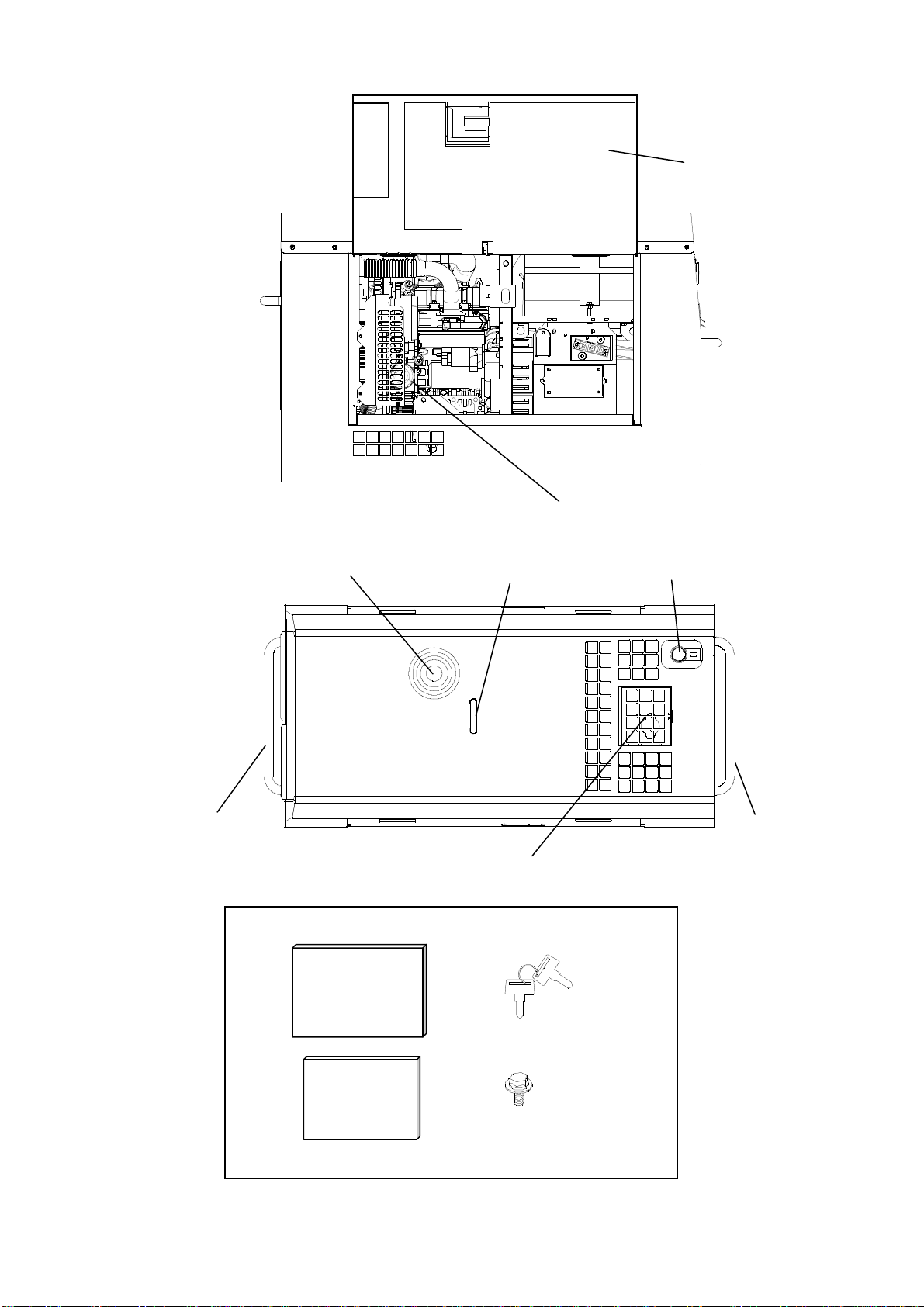
•Do not open the side door during operation and immediately after stopping the
equipment, because some parts/components (flexible tube, resistors, etc.) can
reach very high temperature inside the equipment.
Caution : Injuries
•When lifting the equipment, always use a lifting lug. Do not lift a handle, for it
may cause equipment to drop due to handle breaking off.
•When carrying the equipment by trucks, fix it strongly to keep the equipment
from sliding.
•Always place the equipment on a flat and stable surface, to keep the
equipment from sliding. Be sure to lock the wheels for with wheel type.
•When starting the engine, turn off the connected equipment and set the circuit
breaker to OFF position.
•Do not move the equipment during operation.
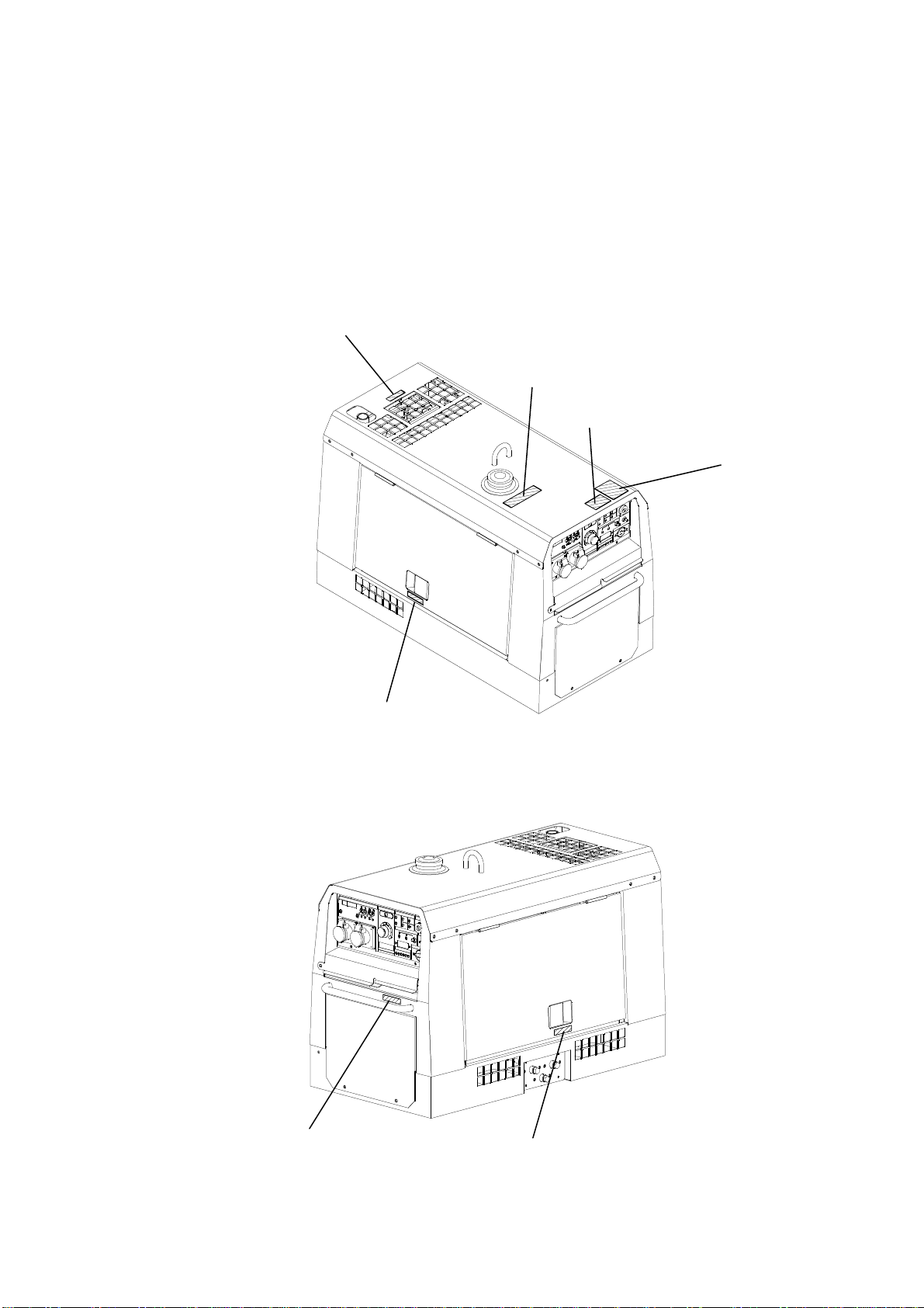
•When performing equipment check and maintenance, always stop the engine.
•Do not operate the equipment, if the equipment is being modified or if the
parts are removed.

- 4 -
■
■■
■Location of Warning labels
When any warning label becomes unreadable or damaged, place a new label on
the appropriate location.
When ordering a new label, use the following part number.
①Suffocation from exhaust fume (No. X505-004 90 0)
②Suffocation from welding fume (No. X505-004 91 0)
③Electric Shock (No. X505-004 93 0)
④Injuries (No. X505-004 94 0)
⑤Burns (No. X505-004 95 0)
⑥Fire (No. X505-004 88 0)
⑥
④
③
①
②
④
⑤

- 5 -
Model DGW300M/EASIA
Generating Method Rotating Field
Rated Current (A)
260/280
Rated Voltage (V)
30.4/31.2
Duty Cycle (%)
50
Rated Speed (min
-1
)
3000/3600
No Load Voltage (V)
MAX 85
Current Adj. Range
(A)
30~280/30~300
ECO Welding Rod (mm)
2.0~6.0
Current Adj. Range
(A)
35~280/40~300
Welding DC Generator
AUTO/
HIGH Welding Rod (mm)
2.0~6.0
Rated Frequency (Hz)
50/60
Rated Speed (min
-1
)
3000/3600
Phase 1-Phase
Rated Voltage (V)
200/220
Rated Current (A)
11A×2
Power Factor 1.0
Rated Output (kVA)
4.4/4.8
AC Generator
Rating Continuous
Model Kubota Z602
Type Water-Cooled 4-Cycle Diesel Engine
Displacement (L)
0.599
Rated Output (kW/min
-1
)
12.5/3600(Gross Intermittent)
Fuel ASTM No.2 Diesel Fuel or Equivalent
Lubricant Oil API Class CD or Higher
Lubrication Oil Volume (L)
2.5 (Effective 0.8)
Cooling Water Volume (L) 3.0 (Sub Tank Capacity 0.6 L included)
Engine
Starting Method Starter Motor
Battery 44B19L(Japan Industrial Standard)
Fuel Tank Capacity (L)
25
Length (mm)
1200
Width (mm)
566
Dimen-si
on
Height (mm)
768
Dry Weight (kg) 270
Full Weight (kg)
299
•Arc Welding
•Power Source for Electric Tools and HomeAppliances
•Power Source for Lights
Caution : Damage to the equipment or other properties
•Do not use other than the above purposes.
•Whenever connecting to use medical equipment or appliances, be sure to
consult with the medical equipment company, doctor or hospital
personnel.
2.
. .
. Specifications
3.
. .
. Usage

- 6 -
STARTER SWITCH
IDLE CONTROL
SWITCH
DISPLAY
DISPLAY SELECTOR
SWITCH
REMOTE CONTROL
RECEPTACLE
WELDING OUTPUT
TERMINAL
FUEL METER
MONITOR LAMP
ECO LAMP
BREAKER
1-PHASE
RECEPTACLE
BONNET
GROUNDING
TERMINAL
FUSE
(10A,40A)
SIDE DOOR
AIR CLEANER
OIL GAUGE
COOLANT
SUB TANK
OIL PLUG
OIL INLET
OIL
DRAIN PLUG
FUEL
DRAIN PLUG WATER
DRAIN PLUG
FUEL LEVER
(FUEL STRAINER)
FREQUENCY
CHANGE
SWITCH
4.
. .
. Name of Parts
BATTERY
CURRENT
ADJUSTMENT DIAL
VOLTAGE
REDUCING
DEVICE
SELECTOR
SWITCH
AC VOLTAGE
ADJUSTMENT
DIAL

- 7 -
SIDE DOOR
OIL FILTER
FUEL INLET LIFTING LUG MUFFLER
HANDLE
TOP PLATE
HANDLE
ACCESSORIES
OWNER’S AND
OPERATOR’S
MANUAL
ENGINE
WARRANTY
STATEMENT
ENGINE KEY
1PAIR
M6 BOLT ×1

- 8 -
5-1.
. .
. Eco Welding/
//
/Eco Generating
The equipment is incorporated in Eco Welding/Eco Generating features that are
aimed at performing the lower noise, the lower fuel consumption and the lower gas
emission than conventional models. When you turn the idle control switch to 『ECO』,
the optimum engine speed will be adjusted automatically by load with green “ECO
DRIVE” indicator lamp turned on.
<
Caution >
•The optimum engine speed will be adjusted
automatically while using welding output
only.
•The engine speed will be set slightly lower
than the rated speed while using generating
output only.
•The engine speed will be set as rated
speed while using simultaneous use of
welding and generating.
•The engine speed will be set
automatically as low speed at no load.
•Always turn the idle control switch to 『HIGH』, when using motor with large
capacity or the load is incorporated with any magnet switch.
•When the load of less than 1A is connected to use, the feature does not function
sometimes. Therefore, turn the idle control switch to 『HIGH』.
•When welding operation or electric supply performs alternately or intermittently,
turn the idle control switch to 『HIGH』.
5-2.
..
.Display
The equipment incorporates in digital display. It displays『DC CURRENT』,『AC
VOLTAGE』,『HOUR』successively, by changing the display selector switch.
<
Caution >
•During no load operation, the preset current
is indicated on the display with “PRESET”
indicator lamp turned on.
•While welding, the actual current is
indicated on the display with “ACTUAL”
indicator lamp turned on.
•During operation, AC voltage meter always
displays the voltage in 200/220V AC output
both at the breaker position『ON』and
『OFF』.
5-3.
..
.Voltage Reducing Device
Danger : Injuries
•Frequency change should be done, only after stopping the engine. Moreover,
close doors and place locks during operating this equipment, to avoid
injuries by unintentional contact with cooling fan and fan belt.
5.
. .
. Equipment
ECO LAMP IDLE CONTROL
SWITCH
DISPLAY SELECTOR
SWITCH
ACTUAL LAMP
PRESET LAMP

- 9 -
Caution : Burns
•Do not touch the engine and muffler during operation and immediately after
stopping the equipment, for the temperature can reach extremely high.
The equipment incorporates VRD (Voltage
Reducing Device) feature, for the purpose
of protecting an operator from electric
shock with welding output.
When the VRD selector switch is turned to
『ON』, the voltage changes to 35V or
lower during no welding period.
5-4.
..
.AC Voltage Adjustment Dial
Danger : Injuries
•Frequency change should be done, only after stopping the engine. Moreover,
close doors and place locks during operating this equipment, to avoid
injuries by unintentional contact with cooling fan and fan belt.
Caution : Burns
•Do not touch the engine and muffler during operation and immediately after
stopping the equipment, for the temperature can reach extremely high.
Adjust the dial whenever the AC output
voltage adjustment is necessary.
<
Caution >
•When raising the voltage, the current is
decreasing. (Use the output within the
output capacity.)
•In you raise the voltage exceeding the
allowable voltage range, which causes the
damage to the loads.
5-5.
..
.Frequency Change
Danger : Injuries
•Frequency change should be done, only after stopping the engine. Moreover,
close doors and place locks during operating this equipment, to avoid
injuries by unintentional contact with cooling fan and fan belt.
Caution : Burns
•Do not touch the engine and muffler during operation and immediately after
stopping the equipment, for the temperature can reach extremely high.
AC VOLTAGE ADJUSTMENT DIAL
DECREASE
INCREASE
VRD SELECTOR SWITCH

- 10 -
The equipment can be used to 50Hz and
60Hz.
Select the frequency according to the
load by the frequency change switch
located inside of the side door.
<
Caution >
•The monitor lamp will be turned on either 50/60Hz based on the selected
frequency.
5-6.
..
.Monitor Lamp
The equipment is incorporated in
monitoring function of 『WATER
TEMP』,『CHARGE』,『OIL PRESS』.
Under normal condition, when the
starter switch changes from 『STOP』
to『RUN』, all the lamps of『CHARGE』,
『OIL PRESS』will be turned on.
When the engine starts, all the lamps
will be turned off.
When abnormality is detected, the corresponding monitor lamp will flash, and the
engine is automatically shutoff.
When the automatic shutoff is engaged, turn the starter switch to 『STOP』
position once, and then restart the engine. In the event the automatic shutoff is
engaged next time, check which lamp turns on or off and investigate where is the
abnormality.
(1) Coolant/Water Temperature Monitor Lamp
Danger : Injuries
•Close all doors and place locks during operating this equipment, to avoid
injuries by unintentional contact with cooling fan and fan belt.
Caution : Burns
•Do not open the radiator cap while operating this equipment or immediately
after stopping the equipment, to avoid sustaining burns from hot vapor.
•Do not touch the engine and muffler during operation and immediately after
stopping the equipment, for the temperature can reach extremely high.
When the water temperature rises abnormally, the coolant/water temperature
monitor lamp will be flashing, and the automatic shutoff will be engaged.
When this occurs, check the coolant/water reservoir tank, and replenish if needed.
(Refer to『6-2. Checking coolant/water』)
If the water level is normal, there may be a possibility of overloading. Always use
the equipment within the rated duty cycle and output.
(2) Battery Charge Monitor Lamp
When the battery turns unable to be charged during operation, the battery charge
monitor lamp will be flashed and the automatic shut-off will be engaged.
In the event this occurs, consult with authorized distributor.
FREQUENCY
CHANGE
SWITCH
OIL PRESSURE
BATTERY
CHARGE
WATER TEMP

- 11 -
< Caution >
•The battery charge monitor cannot detect the degradation of the battery nor the
battery fluid level. Check the battery fluid level periodically.(Refer to『6-5.Checking
Battery』)
(3) Oil Pressure Monitor Lamp
Danger : Injuries
•Close all doors and place locks during operating this equipment, to avoid
injuries by unintentional contact with cooling fan and fan belt.
Caution : Burns
•Do not touch the engine and muffler during operation and immediately
after stopping the equipment, for the temperature could reach extremely
high temperature.
•When checking engine oil, always stop the engine, and wait until the
engine cools down. If you open either the oil gauge or the oil filter cap
during operation, hot oil may spilled out.
When the engine oil pressure drops during operation, the oil pressure monitor lamp
will flash, and the automatic shutoff will be engaged.
When this symptom occurs, check the engine oil level, and replenish to the
maximum level if needed.
< Caution >
•The engine oil pressure monitor cannot detect the deterioration of engine oil itself.
Check the engine oil periodically, and change if needed.(Refer to『11.Inspection
and Maintenance』)
•Check the fuse next, when the abnormality, other than 『WATER TEMP』,
『CHARGE』or 『OIL PRESS』is detected.
If the fuse is burned out, consult with authorized distributor, as there may be an
abnormality of electrical components or wiring which would be inspected.
5-7.
..
.Remote Control(Option)
The equipment incorporates with remote control receptacle feature.
Remote control boxes are the optional parts.
Remote control operation is available by connecting the compatible remote
controller to the receptacle.Adjust the welding current at the remote area from the
machine.
<
Caution >
•When the remote control box is connected, the current adjustment dial of the
equipment’s front panel will not work.
•When the plug of remote control box has disconnected while welding, the current
adjustment dial of the equipment will work. It may affect to increase or decrease
the current accidentally.
REMOTE
CONTROL
RECEPTACLE
REMOTE
CONTROL BOX

- 12 -
•Never connect the plug of the remote control box to the receptacle of the extension
cable reel when the reel is connected toAC output receptacle.
•Never connect the other loads additionally than the remote control box.
•In the case the extension cable reel is installing the breaker, use the equipment to
have turned the breaker 『ON』.
Caution : Fire・
・・
・Burns・
・・
・Injuries
•When checking engine, always stop the engine, and keep away from fire.
Wait until the engine cools down, before performing any inspection.
6-1.
..
.Checking Engine Oil
When checking for engine oil, be sure
to keep the equipment leveled, and
insert the oil gauge firmly.
Prior to starting the equipment, make
sure to fill the engine oil to the UPPER
line through the oil inlet.
<
Caution >
•If the equipment is not leveled, you cannot
obtain accurate oil level.
Do not overfill (over UPPER line) the engine
oil. The excessive amount of engine oil may
damage the engine (inside the cylinders)
■Selecting proper engine oil
<
Caution >
•Use the API class CD or higher.
Temperature Over +20℃+10℃~+20℃-10℃~+40℃
Viscosity SAE30 SAE20 SAE10W/30
6-2.
..
.Checking Coolant / Water
Danger : Injuries
•Close all doors and place locks during operating this equipment, to avoid
injuries by unintentional contact with cooling fan and fan belt.
Caution : Burns
•Do not open the radiator cap while operating this equipment or immediately
after stopping the equipment, to avoid sustaining burns from hot vapor.
•Do not touch the engine and muffler during operation and immediately after
stopping the equipment, for the temperature could reach extremely high
temperature.
Check to see if the coolant/water level is between FULL and LOW levels in the
coolant sub tank. If the coolant/water is below the LOW level, fill the tank and the
radiator accordingly.
UPPER LEVEL
EFFECTIVE
LOWER LEVEL
6.
. .
. Initialization and Pre-operation check
OIL GAUGE
OIL
INLET

- 13 -
(1) Filling to the Coolant Sub Tank
①Remove the coolant sub tank cap.
②Fill up the coolant sub tank to the
FULL level.
③Install the cap back.
(2) Filling to the Radiator
①Open the top plate.
②Remove the radiator cap.
③Fill the radiator up to the top.
④Install the cap back and tighten.
⑤Close the top plate.
< Caution >
•Use Long Life Coolant (LLC), for prevent
freeze and rust.
(30%mixture LLC is filled when shipped
from factory)
•Mixture ratio of the coolant should be
30%-45%, depending on the ambient
temperature.
•Replace LLC at every year or 2000 hours.
Mixture Ratio (for reference only)
LowestAmbient
Temperature -15℃ -20℃ -30℃
Mixture Ratio 30% 35% 45%
6-3.
..
.Checking Fuel
Caution : Fire
•Always wipe any drip of fuel. Do not use this equipment when leakage is
found. Repair the equipment before use.
Check for the fuel level in the tank.Add if necessary.
After adding fuel, retighten the tank cap securely.
< Caution >
•Use Diesel fuel, ASTM D975 No.2-D in the
event ambient temperature reaches down
to -5℃.
•Always use No.2-D diesel fuel. You are
required not to use alternative fuel,
because its quality is unknown or it may be
inferior in quality.
COOLANT
SUB TANK
TANK CAP
FUEL
STRAINER
CAP
RADIATOR
CAP
TOP PLATE
FUEL INLE
T
COOLANT
SUB TANK
LOW
FULL
WATER
INLET

- 14 -
•At temperatures less than -7℃(20℉), No.2-D fuel may pose operating problems. At
colder temperatures, use No.1-D fuel (if available) or use a “winterized” No.2-D (a
blend of No.1-D and No.2-D). This blended fuel is usually called No.2-D also, but
can be used in colder temperatures than No.2-D fuel which has not been
“winterized”. Check with the services stations operator to be sure you can get the
properly blended fuel.
•Always use the fuel strainer.
•Fill the fuel tank slightly less than the full tank.
•Diesel fuel specification type and sulfur content %(ppm) used, must be compliant
with all applicable emission regulations for the area in which the engine is
operated.
6-4.
..
.Checking Fuel, Engine Oil and Water Leakage
Caution : Fire
•Do not use this equipment when leakage is found. Repair the equipment
before use.
Be sure to check any leakage for fuel, oil and coolant/water at the hose connections
by opening side doors. Whenever checking any fuel leakage, turn the fuel lever
『OPEN』and be sure to close the fuel lever after checking.
6-5.
..
.Checking Battery
Caution : Injuries to eyes and skin
•Battery fluid contains diluted sulfuric acid. Avoid contact with eyes, skin or
clothing.
•If the acid comes to contact, especially with eyes, flush with a lot of water,
and contact your physician immediately.
Caution : Explosion
•Do not use the equipment or charge the battery, in the case the battery fluid
level is lower than the LOWER level.
•Battery may emit some combustible gas, so keep it away from fire and sparks.
① Check the fluid level. If the level is near or lower
than LOWER level, add distilled water until the
fluid level reaches UPPER level.
② Make sure that the battery cables are firmly
secured to the posts. Tighten the clamps if
necessary.
< Caution >
•Check the hydrometer of the battery fluid. If it falls below 1.23, the battery requires
recharging. Please consult with authorized distributor.
■Replacing battery
① Remove the clamp and cable from
negative 『
-
』post on the battery.
(Remove always negative side first)
② Remove the hold-down clamp from the
battery.
INS CAP
+POST -POST
HOLD-DOWN CLAMP
UPPER
LEVEL
TERMINAL
LOWER
LEVEL

- 15 -
③ Remove the clamp and cable from positive 『
+
』post on the battery.
④ Remove the battery from the seat.
※Reinstall a new battery in the reverse order.(Install always the cable to the positive
『
+
』post in the new battery first.)
< Caution >
•Use the following battery.<Japan Industrial Standard : 44B19L>
Danger : Suffocation from exhaust fume
•Exhaust fume from the engine contains many elements harmful to human.
Do not operate this equipment in poorly ventilated area, such as inside a
room or in a tunnel.
Caution : Suffocation from exhaust fume
•Do not redirect the exhaust fume toward pedestrians or building.
Caution : Fire
•Temperature around muffler and exhaust can get extremely high. Keep any
inflammable items (such as fuel, gas, paint, etc.) away from the equipment.
•Always operate this equipment on flat surface and, at least 1 meter away
from any objects (wall, box, etc.)
Caution : Injuries
•Always place the equipment on a flat and stable surface, to keep the
equipment from sliding.
•Before starting the engine, be sure to disconnect the loads and set the
breaker to 『OFF』position.
Caution : Burns
•Do not touch the engine and muffler during operation and immediately
after stopping the equipment, for the temperature could reach extremely
high temperature.
< Caution >
•Check to see if it is safe around the equipment before starting.
•When working is performed together by two or more persons, take care to perform
all work safely.
•Do not use the location of dusty, hot and humid.
•Close all doors and place locks during operating this equipment, to damage the
equipment by decrease of cooling performance.
•When the equipment is noisy, it use additional hearing protection item to prevent
the abnormal auditory.
7-1.
..
.Starting
① Turn the breaker to『OFF』.
② Turn the fuel lever to『OPEN』.
③ Turn the idle control switch to『ECO』or『AUTO』.
④ When the temperature is below -5℃,turn and keep the Starter switch to
『PREHEAT』until the preheat lamp turns off (about 5 seconds).
7.
..
.Operating the Engine

- 16 -
⑤ Turn the starter switch to『START』and then the engine starts by the starter
motor.
⑥ Release the starter switch, as soon as the engine has started.
⑦ Keep the engine idle for about 5 minutes.
< Caution >
•Do not drive the starter motor for more than 15 seconds successively.
•If you need to restart, wait for 30 seconds or more before reattempt.
•Once the engine has started, never turn the starter switch to『START』.
■Restart after stopping due to fuel shortage
This equipment is incorporated in automatic vacuuming air feature. Therefore, even
though the engine stops due to running out of fuel, you can restart the engine easily
by the following steps.
① Turn the breaker to『OFF』.
② Turn the Starter Switch to『STOP』.
③ Fill the fuel.
④ Turn the idle control switch to『ECO』or『AUTO』.
⑤ Turn the starter switch to『START』and drive the starter motor for about 10
seconds.
⑥ Release the starter switch, as soon as the engine has started.
⑦ Wait for about 1 minute to vacuum the air out. The engine speed becomes
stable when the air is extracted.
< Caution >
•Never turn the engine high speed or connect the loads until the air is extracted
completely (the engine speed becomes stable).
7-2.
..
.Stopping
① Turn the breaker to『OFF』.
② Turn the idle control switch to『ECO』or『AUTO』.
③Keep the engine idle (cooling down) for about 5 minutes.
④ Turn the starter switch to『STOP』.
⑤ After the engine has stopped, turn the every fuel lever to『CLOSE』.
< Caution >
•When the engine does not stop in spite of turning the starter switch to『STOP』,
Turn the fuel lever to『CLOSE』, then the engine will stop in a few minutes.
In this case, be sure to consult with authorized distributor and ask to repair.
•Do not attempt to turn to『STOP』position while actual welding or utilizing AC power
source, it may cause the serious damage on the unit.
CLOSE
OPEN
FUEL LEVER
BREAKER
IDLE CONTROL SWITCH
STARTER
SWITCH
PREHEAT LAMP

- 17 -
8-1.
..
.Selection – Welding Cable
Select the cable with proper gauge, based on the allowable amperage and the
length, per the table shown below.
The welding capacity is to reduce if the small gauge cable is used.
< Caution >
•Welding cables should be used unstrained. When the welding cables are used in
swirl, the welding capacity is to reduce.
Size of Cable(Unit:mm
2
)
Return
Length
Welding Current 20m 30m 40m 60m 80m 100m
300A 30 38 50 80 100 125
250A 22 30 38 60 80 100
200A 22 30 30 50 60 80
150A 22 22 22 38 50 60
100A 22 22 22 30 30 38
8-2.
..
.Polarity
There are two welding output terminals,『+
++
+』and『-
--
-』.
Select the polarity according to the operation, referring to the table below.
< Caution >
•Follow the instruction of the welding rods, the polarity of which is specified.
•If connected by different polarity and the same work is simultaneously used by two
types of machine, the voltage between folders may receive an electric shock.
That one operator has two folders absolutely should avoid.
8-3.
..
.Connection – Welding Cable
Danger : Electric Shock
•Before connecting or disconnecting a welding cable from welding output
terminals, stop the engine, and remove the engine key. A person performing
should always keep the key.
① Stop the engine.
② Connect a welding cable to a crimping terminal, a welding rod holder and a
material holder.
③ Connect a welding cable to a welding output terminal.
④ After connecting cables, be sure to close output terminal covers and fit it with
the bolt.
Application Connection
Normal Polarity Generals Welding, such as
Construction Minus to holder (Rod)
Plus to the Earth (Material)
Reverse Polarity Thin Plate, Build-Up Welding
Stainless Steel Minus to the Earth (Material)
Plus to holder (Rod)
8.
..
.Welding Operation
Table of contents
Other Shindaiwa Welding System manuals

Shindaiwa
Shindaiwa DGW340DM User manual

Shindaiwa
Shindaiwa DGW400DM-C User manual

Shindaiwa
Shindaiwa DGW311DM User manual

Shindaiwa
Shindaiwa DGW500DM User manual

Shindaiwa
Shindaiwa DGW310DMC User manual

Shindaiwa
Shindaiwa DGW400DM-380A User manual

Shindaiwa
Shindaiwa EGW165M-I/UKV User manual

Shindaiwa
Shindaiwa 3 Series User manual