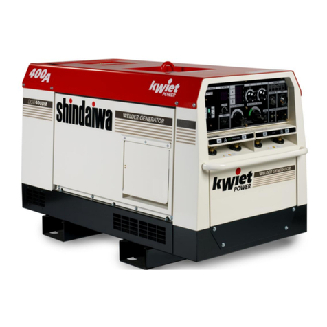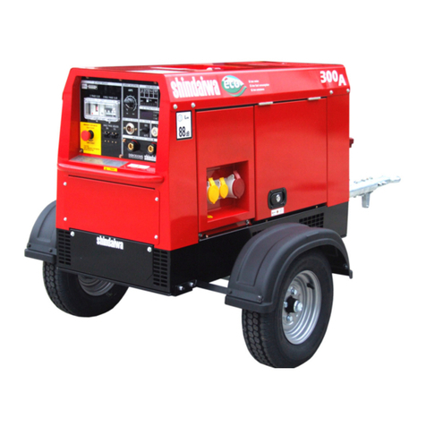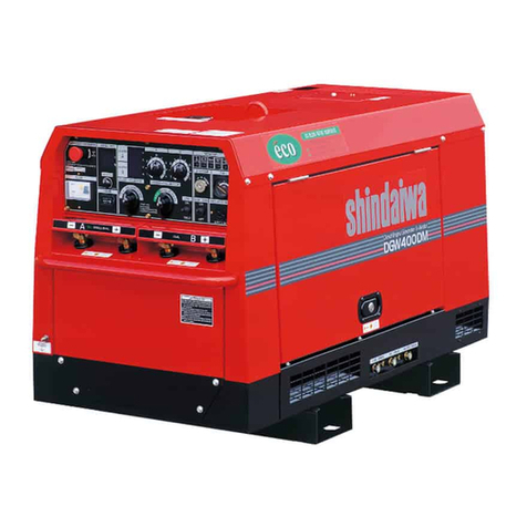
POWERCENTER 15
PC15-OM-Vs: 1
Shindaiwa Limited
Four Ashes, Wolverhampton, UK
T: +44 (0)1902 791855
Table of Contents
1. 1.Safety Guidelines ............................................................................. 2
2. Specifications...................................................................................... 5
3. Use........................................................................................................ 5
4. Parts ..................................................................................................... 6
5. Equipment............................................................................................ 8
5-1. Welding Output Control..............................................................8
5-2. VRD........................................................................................... 9
5-3. Output Remote Control............................................................. 9
5-4. Operation Mode Selector ......................................................... 10
5-5. Meter ........................................................................................ 10
5-6. Monitor Lamp............................................................................. 11
5-7. Earth Leakage Relay ............................................................... 13
6. Initialization and Pre-Check ............................................................. 15
6-1. Checking Engine Oil................................................................ 15
6-2. Checking Coolant .................................................................... 15
7. Operation ............................................................................................ 18
7-1. Starting .................................................................................... 18
7-2. Stopping................................................................................... 19
7-3. Emergency Stopping............................................................... 19
8.Welding Operation .............................................................................20
8-1. Selection of Welding Cable..................................................... 20
8-2. Polarity .................................................................................... 20
8-3. Connection of Welding Cable ................................................. 21
5-8. Auto Idle Feature ..................................................................... 14
5-9. Emergency Stop Switch .......................................................... 14
5-10. Battery Isolator ...................................................................... 14
6-3. Checking Fuel ......................................................................... 16
6-4. Checking for Leaks ................................................................. 17
6-5. Checking Battery .................................................................... 17
8-4. Duty Cycle .............................................................................. 22
8-5. Welding ................................................................................... 22
9.Generating Operation .......................................................................23
9-1. Output Range ........................................................................ 23
9-2. Output Limitation ................................................................... 24
9-3. Operation ............................................................................... 24
10.Simultaneous Use of Welder And Generator ................................26
11.Checking and Maintenance .............................................................26
12.Long Term Storage ..........................................................................31
13.Trouble Shooting .............................................................................32


