SHOOTOOLS AUTOPAN User manual
1MADE IN IT ALY
AUTOPAN
INSTRUCTION MANUAL
MANUALE D’ISTRUZIONE
UPDATE THE
FIRMWARE
http://bit.ly/supportarea

2

3
WARNINGS: AUTOPAN INSTRUCTIONS - Read carefully the instructions before use
SHOOTOOLS DEVICES ARE USED FOR THE MANUAL OR ELECTRIC MOTION OF CAMERAS AND VIDEOCAMERAS.
This instructions manual form an integral part of the device and must be attached to it at the time of purchase.
Please contact your reseller, ShooTools or visit www.shootools.com to request any updates of this manual.
The producer reserves the material and intellectual property of this writing and prevents the disclosure and the reproduction,
even partial, without any previous written approval. This manual has been done on purpose by the producer in order to
provide his customers with all the information about the device and the related safety rules, as well as with the use and
maintenance instructions which allow to make the best use of the device potential, keeping its eciency intact over time.
ShooTools devices are subject to continuous updates, that is why they can have some dierent components from what
illustrated; please contact the producer or visit www.shootools.com to obtain updated information.
The incorrect use of this device and improper maintenance operations can cause massive damage to people, animals and
objects.
The operators and the personnel must read carefully the contents of this manual before using the device or carrying out
maintenance operations. It is forbidden to carry out operations if procedures are not completely understood. If during
use or maintenance operations accidents which involve people, animals or objects occur, this means that the procedures
indicated in this manual have not been followed.
The procedures and the precaution measures indicated in this manual are meant to be applicable to the device only for the
uses permitted. If the device is used in a dierent way from the permitted one, the operator is responsible for his safety and
the safety of other people, animals and objects if involved.
This manual must be kept carefully for the duration of the device and must be handed over to any other user or following
owner.
Contact the reseller or ShooTools for any information about spare parts or accessories.
BATTERY CHARGERS AND ELECTRONIC DEVICES
To charge the battery chargers please only use the battery charger provided together with the device.
Do not use power supplies for the battery charge. Do not leave the device in charge in a not aired and unattended place.
During the charge period, always keep the Controller away from any material which can be modified by heat.
Always end the charge procedure if the Controller warms up or starts changing shape during the charge procedure. Do not
use the battery charger if the plug or the cable are damaged. Do not charge the batteries in very hot, cold or exposed to
direct sunlight places.
Do not open or tamper with electric-electronic devices, if you do the warranty will be void.
Do not replace the internal batteries: should the device performance slow down, please contact your reseller or ShooTools.
Do not persist in moving the motor if it is not able to move its load in a fuid and easy way.
Do not use cables dierent to the ones provided together with the device; by necessity, please contact your reseller or
ShooTools.
AUTOPAN AND MECHANIC DEVICES WITH MANUAL AND ELECTRIC MOTION
During the use of the device do not touch the parts in motion, pay attention to the points where there is possibility of
fingers or hands crushing.
Be sure of the device load capacity reading the settings for use.
Be sure that the device is well fixed and not unstable.
Be sure that the camera is well fixed to the head that supports it and that the head is well fixed to ShooTools device.
Do not use the device if the supports (tripods, lightstands, monopods, legs, quick release systems, other types of fixing
and support) are not well fastened yet and if they are not a safe foothold. Stop any procedure and contact the reseller or
ShooTools if the product does not work.
THE MANUFACTURER SHALL NOT BE HELD RESPONSIBLE FOR DAMAGE TO PEOPLE, ANIMALS OR OBJECTS, CAUSED BY
FAILURE TO COMPLY WITH THE CONTENT OF THIS MANUAL.
AUTOPAN MAXIMUM LOAD CAPACITIES
PAYLOAD 22 lb // 10 kg
MAX. SPEED 21°/s
ENCODER WIRE 9,8 ft // 3 mt
Features registered with AutoPan horizontally installed with balanced loads

4
AVVERTENZE LIBRETTO AUTOPAN - Prima dell’uso leggere attentamente le istruzioni.
I DISPOSITIVI SHOOTOOLS SONO IMPIEGATI PER LA MOVIMENTAZIONE MANUALE O ELETTRICA DI FOTOCAMERE E VIDEOCAMERE.
Il presente manuale viene considerato come parte integrante del dispositivo al quale deve essere allegato al momento
dell’acquisto.
Contattare il rivenditore, ShooTools o visionare il sito internet www.shootools.com per richiedere eventuali aggiornamenti
del presente manuale. Il costruttore si riserva la proprietà materiale ed intellettuale della presente pubblicazione e ne vieta
la divulgazione e la duplicazione, anche parziale, senza preventivo assenso scritto. Questo manuale è stato voluto dal
costruttore per fornire al cliente tutte le informazioni sul dispositivo e sulle norme di sicurezza ad esso collegate, nonché
le istruzioni d’uso e di manutenzione che permettono di sfruttare al meglio le potenzialità del dispositivo, mantenendone
integra l’ecienza nel tempo.
I dispositivi ShooTools sono soggetti a continui aggiornamenti, per questo possono montare particolari diversi da quelli
illustrati, consultare il costruttore o il sito internet: www.shootools.com per avere eventuali informazioni aggiornate.
L’uso scorretto di questo dispositivo ed operazioni di manutenzione improprie comportano pericoli che possono causare
seri danni a persone, animali e cose. Gli operatori e le persone addette devono leggere attentamente tutto il contenuto di
questo manuale prima di usare il dispositivo o di eseguire operazioni di manutenzione. E’ vietato procedere alla realizzazio-
ne di operazioni delle quali non si sono capite le modalità.
Se durante l’uso e la manutenzione si verificano incidenti che coinvolgono persone, animali o cose, significa che non sono
state rispettate tutte le modalità indicate in questo manuale. Le procedure e precauzioni contenute in questo manuale si
intendono applicabili al dispositivo solo per gli usi consentiti.
Se il dispositivo viene usato in modo diverso dal consentito, l’operatore è responsabile della sicurezza sua e delle persone,
animali e cose eventualmente coinvolte. Il manuale deve essere conservato con cura per tutta la vita del dispositivo ShooTo-
ols e deve essere trasferito a qualsiasi altro utente o successivo proprietario. Consultare il rivenditore o ShooTools per ogni
necessità di informazione, ricambi o accessori.
CARICABATTERIE E DISPOSITIVI ELETTRONICI
Per la carica degli accumulatori utilizzare solo il caricabatterie fornito in dotazione con il dispositivo.
Non utilizzare alimentatori per la carica delle batterie. Non lasciare il dispositivo in carica in un ambiente non ventilato e non
custodito. Durante la carica tenere sempre il Controller lontano da qualsiasi materiale che possa essere alterato dal calore.
Terminare sempre il processo di carica se il Controller si riscalda troppo o inizia a deformarsi durante il procedimento di
carica.
Non utilizzare il caricabatterie se la presa o il cavo sono danneggiati. Non caricare mai le batterie in luoghi estremamente
caldi o freddi o esposti alla luce diretta del sole. E’ assolutamente vietato aprire o manomettere i dispositivi elettrici-elettroni-
ci, pena la decadenza della garanzia.
Non sostituire le batterie interne, se le prestazioni del dispositivo diminuissero, contattare il rivenditore o ShooTools.
Non insistere nella movimentazione se il motore non riesce a movimentare il carico in modo fluido ed agevole.
Non utilizzare cavi diversi da quelli forniti con il dispositivo, in caso di necessità contattare il rivenditore o ShooTools.
DISPOSITIVI MECCANICI A MOVIMENTAZIONE MANUALE ED ELETTRICA
Durante l’utilizzo del dispositivo non toccare le parti in movimento, fare attenzione ai potenziali punti di schiacciamento
delle dita e delle mani. Accertarsi della portata del dispositivo nella configurazione di utilizzo.
Accertarsi che il dispositivo sia ben fissato e non traballante. Accertarsi che la videocamera/fotocamera sia ben fissata alla
testa che la sostiene e che quest’ultima sia ben fissata al dispositivo ShooTools. Non utilizzare il dispositivo se i supporti
utilizzati (cavalletti, stativi, monopiedi, piedini, sganci rapidi, altri tipi di fissaggio e sostegno) non risultano ben ancorati e se
non forniscono una sicura base d’appoggio.
Interrompere sempre qualsiasi processo e rivolgersi al rivenditore o a ShooTools, se il prodotto funziona male.
IL COSTRUTTORE DECLINA OGNI RESPONSABILITA’ PER EVENTUALI DANNI A PERSONE, ANIMALI O COSE, CAUSATI
DALLA NON OSSERVANZA DI QUANTO RIPORTATO NEL PRESENTE MANUALE.
CAPACITA’ MASSIME DELL’AUTOPAN
PORTATA 10 kg
VELOCITÀ MAX 21°/s
FILO ENCODER 3 mt
Caratteristiche rilevate con AutoPan installato orizzontalmente con carichi bilanciati.

5
CONTENTS
SOMMARIO
Components
Componenti
Getting Started
Informazioni Preliminari
Set-up
Installazione
Settings
Programmazione
Firmware up
grade
procedure for Windows Vista , Windows 7 e Windows 8.0
Aggiornamento del firmware per Windows Vista , Windows 7 e Windows 8.0
Firmware up
grade
procedure Windows 8.1 e Windows 10
Aggiornamento del firmware per Windows 8.1 e Windows 10
Firmware up
grade
procedure for Mac Os X
Aggiornamento del firmware per Mac Os X
Datasheets & Certifications
Schede Tecniche e Certificazioni
page 6
pag. 6
page 7
pag. 7
page 8-9
pag. 8-9
pag. 10
page 10
pag. 11
page 11
pag. 12
page. 12
pag. 13
page. 13
pag. 14
page. 14
6
1
2
3
4
5
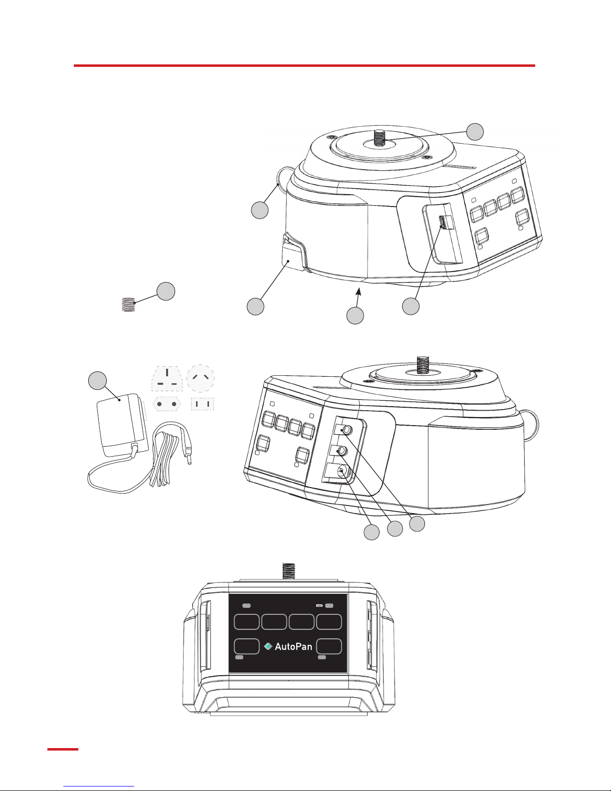
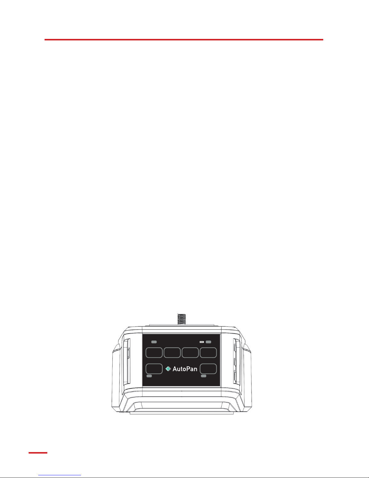
(1) Usb (only for update firmware, no charging)
(2) Release Button
(3) Shutter Release
(4) External Sensor
(5) Power: 9V - 1A DC ( max 9W )
(6) 1/4” thereaded pin
(7) 3/8” thereaded hole
(8) Adapter 1/4” 3/8”
(9) Battery charger
(10) Sync Wire
AUTOPAN
AUTOPAN
SET
KEY FRAME
ROTATE
CW
ROTATE
CCW
END
KEY FRAME
MADE IN ITALY
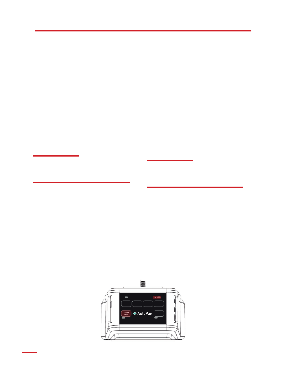
Status
WI-FI
ON/OFF
POWER
ON/OFF
6
7
10
9
8
7
SET
KEY FRAME
ROTATE
CW
ROTATE
CCW
END
KEY FRAME
MADE IN ITALY
Status
WI-FI
ON/OFF
POWER
ON/OFF
GETTING STARTED
INFORMAZIONI PRELIMINARI
Connect the adapter to Autopan’s charging connector,
insert the adapter into a wall power outlet compatible
with a 110-240V power source.
Turn on Autopan to visualize the state of the battery
level.
The charging of AutoPan starts in any status: on or
turned o
Even if AutoPun is turned o, the batteries are in charg-
ing. To know the statuts of the charge, turn on AutoPan.
CHECK THE BATTERY LEVEL
The multicolour LED shows the battery level and the
charging state:
NOT CHARGING TIME:
Fixed green:battery level between 61% and 100%
Fixed orange: battery level between 31% and 60%
Fixed red: battery level between 0% and 30%
CHARGING TIME:
Pulsating green: battery level 100%
Pulsating orange: battery level between 31% and 99%
Pulsating red: battery level between 0% and 30%
TURNING ON THE POWER
Briefly press POWER ON/OFF button, in 1 second the
device turns on, its white LED POWER ON/OFF lights,
the battery level led is activate.
TURNING OFF THE POWER
Briefly press the POWER ON/OFF button, all the LEDS
turn o.
Collegare l’alimentatore al connettore di ricarica dell’Au-
toPan, connettere l’alimentatore ad una presa a muro
110-240V.
E’ possibile utilizzare l’AutoPan anche durante la carica.
Il led fornirà indicazioni sullo stato della batteria come
riportato sotto.
La gestione della carica inizia appena l’alimentatore vie-
ne connesso, indipendentemente dallo stato di accen-
sione o spegnimento dell’AutoPan.
Se l’AutoPan è spento il led di stato della batteria rimane
spento ma la gestione di carica della batteria continua.
Per visualizzare lo stato di carica della batteria, accen-
dere l’AutoPan.
LED STATO DELLA BATTERIA
Il led multicolore fornisce indicazioni sullo stato della
batteria e della ricarica.
NON IN CARICA
Verde fisso: batteria tra 61% e 100%
Arancione fisso: batteria tra 31% e 60%
Rosso fisso: batteria tra 0% e 30%
IN CARICA
Verde pulsante: batteria 100%
Arancione pulsante: batteria tra 31% e 99%
Rosso pulante: batteria tra 0% e 30%
ACCENSIONI
Premere brevemente il pulsante POWER ON/OFF, entro
1 secondo il dispositivo si accende, il relativo led bianco
POWER ON/OFF si accende, il led dello stato della bat-
teria si accende.
SPEGNIMENTO
Premere brevemente il pulsante POWER ON/OFF, tutti i
led si spengono.
8
NOTE: screw AutoPan until stable but without putting too much
eort: a too strong eort could create an unnecessary stress to
the internal components.
NOTA: avvitare l’AutoPan in modo che risulti stabile ma senza ap-
plicare troppa forza, stringerlo eccessivamente comporterebbe
una inutile sollecitazione dei componenti interni.
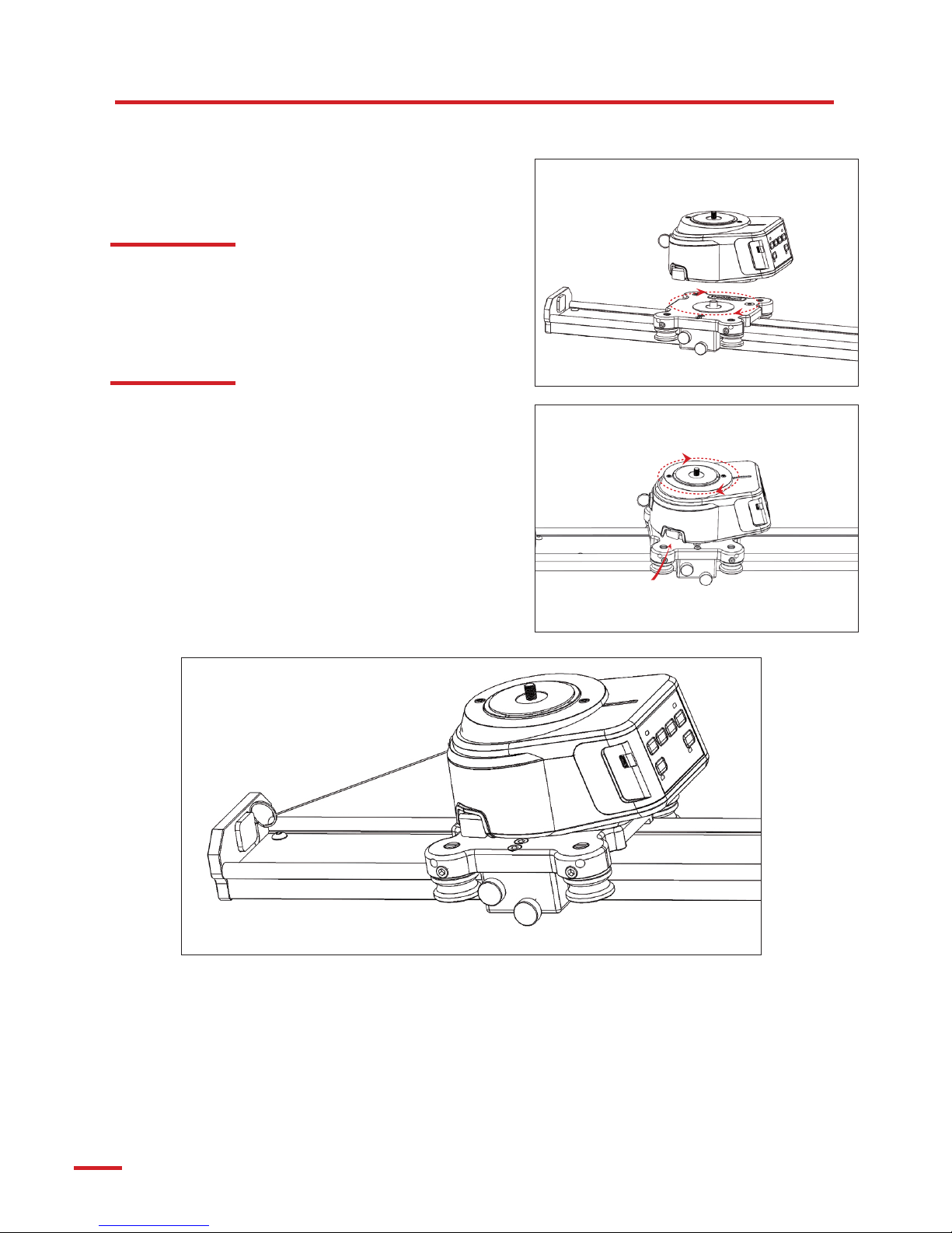
After screwing, it is possible to direct correctly the way out of the
encoder sync wire by pressing the RELEASE BUTTON: releasing
AutoPan temporary, it allows the manual rotation by steps of 45°.
Fix the AutoPan’s encoder sync wire to one of the slider’s end.
Dopo l’avvitamento è possibile direzionare correttamente l’u-
scita del filo encoder premendo l’apposito pulsante di sblocco
RELEASE BUTTON, esso sbloccherà momentaneamente l’Auto-
Pan permettendone la rotazione manuale a step di 45°.
Individuare un punto all’estremità dello slider al quale fissare il filo
encoder, utilizzare le fascette in dotazione.
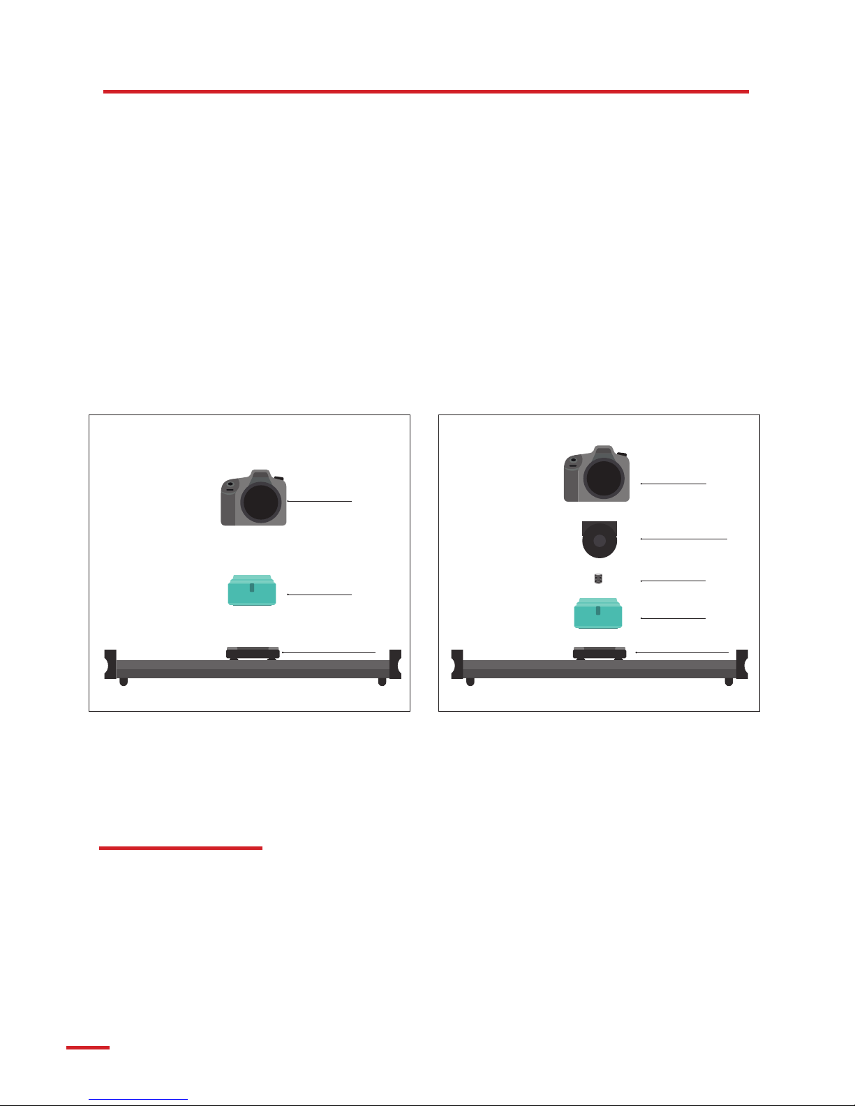
SET-UP
INSTALLAZIONE
Install AutoPan on the slider carriage by screwing it on the
threaded stud of 3/8”.
Installare l’AutoPan sul carrello dello slider, avvitandolo sul perno
filettato da 3/8”.
The encoder wire sync is wound on a spring-loaded
swirl inside AutoPan. When AutoPan moves away from
the selected slider’s end to which the wire sync has been
fastened, it unwinds, while it rewinds when approach-
ing back.
The encoder wire sync provides AutoPan all the needed
details such as position, direction and speed of the car-
riage on the slider, ensuring a synchronized rotation of
the camera.
Il filo encoder è avvolto su un rocchetto a molla all’in-
terno dell’AutoPan. Esso si svolge quando l’Autopan si
allontana dall’estremità dello slider al quale è fissato e si
riavvolge quando si avvicina.
Il filo encoder fornisce all’AutoPan informazioni sulla
posizione, direzione e velocità del carrello dello slider
garantendo la rotazione sincronizzata della camera.
9
AutoPan has got a ¼’’ thread on its top that is compatible
with devices with a 1/4“ threaded hole like cameras,
videocameras, support tools,quick release tools, etc..
An adaptor that converts the ¼’’ thread into a 3/8’’ is
included into the package. The adaptor is suitable for
devices with 3/8” thread such as camera and video
heads, tripods, plates, etc.
Use the adapter only if needed and accordingly to the
specific threadedhole of the device on which AutoPan
is going to be installed.
Slowly screw the device on AutoPan, keepthem parallel
while screwing.
Verify that the weight is balanced on AutoPan’
barycentre.
L’AutoPan è dotato sulla parte superiore, di perno
filettato da 1/4” compatibile con diversi dispositivi dotati
di foro filettato da 1/4” quali: fotocamere, videocamere,
supporti, sganci rapidi, ecc.
In dotazione viene fornito un adattatore che trasforma il
perno di 1/4” in 3/8”, compatibile con diversi dispositivi
dotati di foro filettato da 3/8” quali: teste fotografiche e
video, supporti, videocamere, ecc.
Utilizzare o meno l’adattatore in funzione del foro
filettato presente sul dispositivo da installare sull’AutoPan.
Avvitare lentamente il dispositivo sull’AutoPan
mantenendolo parallelo durante l’avvitamento.
Verificare che il peso sia distribuito sul baricentro
dell’AutoPan.
SET-UP
INSTALLAZIONE
NOTE:set up the deviceuntil stable, but without putting too much eort as it could cause an unnecessary stress to
the internal components.
NOTE: screw the 3/8” 1/4” adaptor on the video head and not directly on AutoPan’s pivot.
NOTA: avvitare il dispositivo in modo che risulti stabile ma senza applicare troppa forza, stringerlo eccessivamente
comporterebbe una inutile sollecitazione dei componenti interni.
NOTA: avvitare l’adattatore 3/8” 1/4” sulla testa video e non direttamente sul perno dell’AutoPan
Camera
Camera
AutoPan
AutoPan
Adaptor
Video head
Slider carriage Slider carriage
10
SET
KEY FRAME
ROTATE
CW
ROTATE
CCW
END
KEY FRAME
MADE IN ITALY
Status
WI-FI
ON/OFF
POWER
ON/OFF
1.Set the carriage on the chosen position for the first
Key Frame.
2. Use ROTATE CW and ROTATE CCW buttons in order
to rotate the camera in the desired position, verify the
pointing accuracy through the viewfinder or the moni-
tor.
3. Press SET KEY FRAME to store the Key Frame.
4. Move the carriage to the next position for the follow-
ing Key Frame.
5. Use the ROTATE CW and ROTATE CCW buttons
to rotate the camera in the desired position, verify the
pointing accuracy through the viewfinder or the moni-
tor.
6. Press SET KEY FRAME to store the following Key
Frame.
7. Operate from step 4 to store other Key frames, it is
possible to store from 2 up to 10 Key Frames.
8. The LED STATUS blinks so many times as the number
of Key Frames stored until that moment.
9.After storing the last Key Frame press END KEY FRAME
to exit the storage procedure.
10. If an error occurs, press at least for 3 seconds END
KEY FRAME in order to reset the stored Key Frames
NOTE: When AutoPan is turned o, the stored Key Fra-Fra-
mes aredeleted.
1.
Portare il carrello sulla posizione relativa al primo Key
Frame.
2. Tramite i pulsanti ROTATE CW e ROTATE CCW, ruota-
re la camera nella posizione voluta, verificare nel mirino
o sul monitor la precisione del puntamento.
3. Premere SET KEY FRAME, il Key Frame viene così me-
morizzato.
4. Spostare il carrello sulla posizione relativa al succes-
sivo Key Frame.
5. Tramite i pulsanti ROTATE CW e ROTATE CCW, ruota-
re la camera nella posizione voluta, verificare nel mirino
o sul monitor la precisione del puntamento.
6. Premere SET KEY FRAME per memorizzare il Key Fra-
me sucessivo.
7. procedere dal punto 4 per memorizzare altri key fra-
me, è possibile memorizzare da 2 a 10 Key Frame.
8. Il led STATUS lampeggia tante volte quanti sono i Key
Frame fino a quel momento memorizzati.
9. Dopo aver memorizzato l’ultimo Key Frame premere
END KEY FRAME per uscire dalla procedura di memo-
rizzazione.
10. In caso di errore, premere per almeno 3 secondi
END KEY FRAME per resettare i Key Frame memorizzati.
NOTA: Quando l’AutoPan viene spento, i Key Frame me-
morizzati vengono cancellati.
SETTINGS
PROGRAMMAZIONE
11
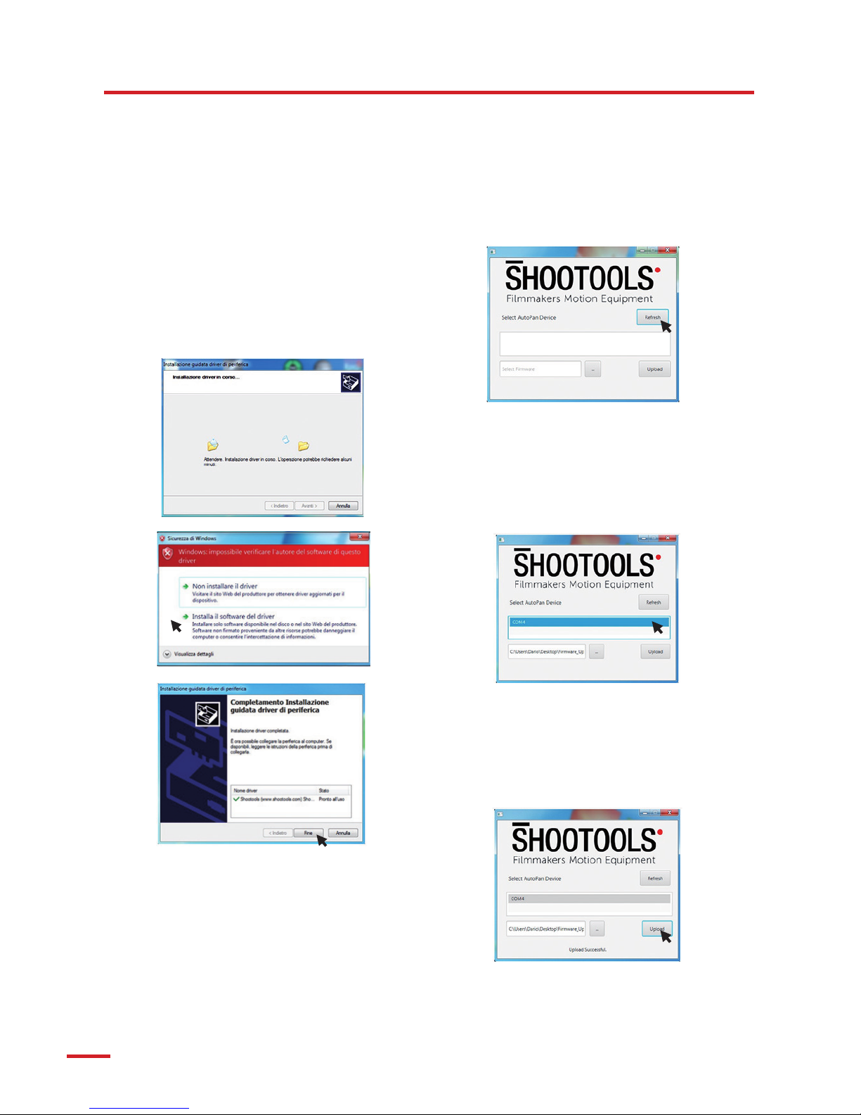
AUTOPAN FIRMWARE UPDATE
PROCEDURE FOR WINDOWS VISTA , WINDOWS 7 E WINDOWS 8.0
1) Install java software from web site www.java.com
(software need for run .jar file)
2) Extract AutoPan driver from archive “Drivers
Vista-7-8.zip”.
3) From Driver directory choose dpinst-x86.exe for
32bit operating systems or dpinst-amd64.exe for
x64bit computers.
4) Confirm driver installation without certification and
check successful operation with ShooTools drivers
installed
5) Extract Autopan upload software from archive“
AutopanUploadTool32-1.0.zip “
6) Restart PC
7) Copy latest firmware file into upload software
directory (firmware_V_xxxxx.bin file)
8) Check AutoPan battery status with green led.
9) Connect AutoPan usb port to high speed pc usb
post 2.0 or 3.0 directly without hub connection.
10) Check AutoPan automatically switch on when
connected and check usb AutoPan Com port ready
on PC without error or driver problems
11) From “upload software” directory start Tool.jar file.
AutoPan software start.
12) Press Refresh button and check Com Port
13) Select from “... button” latest AutoPan firmware
(file.bin)
14) Select Com port from list and press upload button.
15) AutoPan automatically switch o and return on (do
not disconnect or switch o autopan during firmware
upload)
16) When upload is complete a successful message
appear.
17) disconnect AutoPan usb port and check AutoPan
automatically switch OFF.
AutoPan firmware upload is complete.

12
AUTOPAN FIRMWARE UPDATE
PROCEDURE WINDOWS 8.1 E WINDOWS 10
1) Install java software from web site www.java.com
(software need for run .jar file)
2) Install “AutoPanUploadTool32...exe” software.
3) Software automatically create a directory with
correct driver installed, and software link on desktop
for AutoPan firmware Upload.
4) Restart PC
5) Copy latest firmware file into upload software
directory ( firmware_V_xxxxx.bin file )
6) check AutoPan battery status with green led.
7) Connect AutoPan usb port to high speed pc usb
post 2.0 or 3.0 directly without hub connection.
8) Check AutoPan automatically switch on when
connected, and check usb AutoPan Com port ready
on PC without error or driver problems.
9) From desktop start AutoPan Update Tool link.
AutoPan software start.
10) Press Refresh button and check Com Port
11) Select from “... button” latest AutoPan firmware
(file.bin)
12) Select Com port from list and press upload button.
13) AutoPan automatically switch OFF and return
ON (do not disconnect or switch o AutoPan during
firmware upload)
14) When upload is complete a successful message
appear.
15) disconnect AutoPan usb port and check AutoPan
automatically switch OFF.
AutoPan firmware upload is complete.

13
AUTOPAN FIRMWARE UPDATE
PROCEDURE MAC OSX
1) Install java software from web site www.java.com
(software need for run .jar file)
2) RIGHT Click “AutoPan Update Tool V2.1” press
OPEN
3) Follow the software installation steps, You will
find the Icon “AutoPan Update Tool” in your list of
Applications
4) Check AutoPan battery status with green led.
5) Connect AutoPan usb port to high speed pc usb
post 2.0 or 3.0 directly without hub connection.
6) From open “AutoPan Update Tool”
7) Press Refresh button and check Com Port
8) Select from “... button” latest AutoPan firmware
(file.bin)
9) Select Com port from list and press upload button.
10) AutoPan automatically switch o and return on (do
not disconnect or switch o AutoPan during firmware
upload)
11) When upload is complete a successful message
appear.
12) disconnect AutoPan usb port and check AutoPan
automatically switch OFF.
AutoPan firmware upload is complete.

14
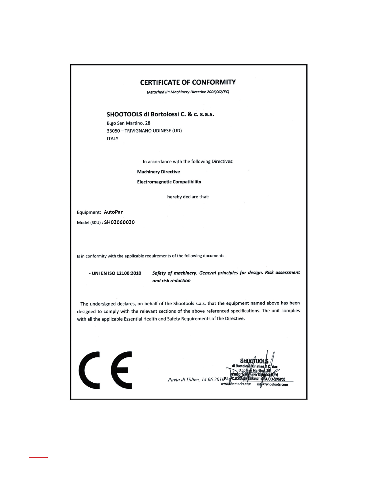
DATASHEET & CERTIFICATIONS
SPECIFICHE TECNICHE E CERTIFICAZIONI
WI-FI MODULE INFORMATION
Model /
Modello
AutoPan
Battery /
Batteria
Li-Ion 7.4V 2000 mAh
Power /
Alimentazione
DC 9V-1A 9W max
Weight /
Peso
900 gr
Dimensions /
Dimensioni
160x120x85 mm
Fixing /
Fissaggio
3/8” - 1/4”
Rotation /
Rotazione
360° continua / Full free
Encoder wire /
Filo Encoder
3 mt // 9,8ft
Input /
Ingresso
External sensor /
Sensori esterni
Output /
Uscita
Shutter release
Payload /
Portata
10 kg
FCC Compliance
This device complies with Part 15 of the FCC Rules.
Operation is subject to the following two conditions: (1)
this device may not cause harmful interference, and (2) this
device must withstand any interference received, including
interference that may cause undesired operation.
Certificazione di Conformità FCC
Questo dispositivo è conforme alla Sezione 15 delle norme
FCC.
Il suo funzionamento è soggetto alle due seguenti
condizioni: (1) questo dispositivo non deve causare
interferenze dannose, e (2) questo dispositivo deve resistere
a qualsiasi interferenza ricevuta, ivi comprese interferenze
che potrebbero comprometterne il funzionamento.
15
-2006/42/EC
-2014/30/CE

16
Disposal of product
At the end of its useful life, the product should be disposed
of in an environmentally compatible way, using its parts and
recycling components and materials.
The “Crossed out Wheelie Bin Symbol” marked on the
equipment or packaging means that the product, at the
end of its useful life, should not be disposed of with general
waste but should be collected separately. Separate waste
collection for this type of equipment at the end of its useful
life is organized and handled by the producer.
The user who intends to dispose of this equipment shall
therefore need to contact the producer and comply with
the system that the latter has adopted for the separated
waste collection. A proper separeted waste collection of the
equipment no longer in use, aimed at an environmentally
compatible recycling, processing and disposal, contributes
to preventing possible negative eects on the environment
and to health, and enhances the reuse and/or recycling of
the equipment components. In case of illegal disposal of
product by the owner, administrative sanctions shall apply as
per law, rules and regulations in force.
Smaltimento del prodotto
Si raccomanda di smaltire il prodotto alla fine della sua vita
utile in modo ambientalmente compatibile, riutilizzando
parti dello stesso e riciclandone componenti e materiali.
Il simbolo del cassonetto barrato riportato sull’apparecchio o
sulla confezione indica che il prodotto alla fine della propria
vita utile deve essere raccolto separatamente dagli altri rifiuti.
La raccolta dierenziata della presente apparecchiatura
giunta a fine vita è organizzata e gestita dal produttore.
L’utente che vorrà disfarsi della presente apparecchiatura
dovrà quindi contattare il produttore e seguire il sistema
che questo ha adottato per consentire la raccolta separata.
L’adeguata raccolta dierenziata per l’avvio successivo
dell’apparecchiatura dismessa al riciclaggio, al trattamento
e allo smaltimento ambientale compatibile contribuisce ad
evitare possibili eetti negativi sull’ambiente e sulla salute
e favorisce il reimpiego e/o riciclo dei materiali di cui è
composta l’apparecchiatura. Lo smaltimento abusivo del
prodotto da parte del detentore comporta l’applicazione
delle sanzioni amministrative previste dalla normativa
vigente.

17
3H00012-01
FIRMWARE UPGRADE AND MORE
AGGIORNAMENTO DEL FIRMWARE E ALTRO
Video Instructions - Firmware Upgrade and More
http://www.shootools.com/public/support/index.html
DISCOVER
more

18

19
VIA GRADO, 4 INT. 5
PAVIA DI UDINE 33050 UD - ITALY
Tel. +39 0432 999583
www.shootools.com
1.0 Logo
C 0 - M 0 - Y 0 - K 10
C 0 - M 100 - Y 100 - K 0
R 0 - G 0 - B 0
R 255 - G 0 - B 0
1.1 Logo negativo
1.2 Logo tagline 1.2.1 Logo tagline negativo
Filmmakers Motion Equipment Filmmakers Motion Equipment
1.3 Logo Social
TRADITION
INNOVATION
PASSION
istruzioni_corrette4.indd 20 11/05/2015 20:07:53
www.shootools.com
Table of contents
Other SHOOTOOLS Camera Accessories manuals


