SHOR-LINE Warming Pad Series User manual

{Save This Guide For Future Reference}
PN: 006.9120.01
Updated: 3.27.15
To reduce the risk of injury, the user must read and understand this guide
before installation of this product.
This product is for animal use only. We do not condone this product for other uses.
A guide for:
Warming Pad
;

{2}
;
Introduction
Thank you for purchasing Shor-Line products. As a leader in animal care equipment, our commitment to you is
exactly the same as it was in 1927.
We hope this guide answers any questions you might have in regards to use, care or installation. If you can’t nd the
answers to your questions, have further questions or would like to purchase additional products, please contact us at
800.444.1579 or 913.281.1500. If in Europe, phone +44 1446 77 20 41.
Consider keeping this guide in a safe and convenient place for future assistance.
For your safety, please follow the instructions on these labels:
This product is for animal use only. We do not condone this product for other uses.
To reduce the risk of injury, the user must read and understand this guide before installation of this product.
Continuous low heat
in one area may burn
a patient.
Improper use of the
grounding plug can
result in risk of electric
shock.
Shor-Line products are
designed for animal
use only.
Do not immerse in
water.
NOTICE
Improper cable
connections can cause
product malfunction.
Failure to follow proper
connection procedures
may result in a void of all
Shor-Line warranties.
{Shor-Line}
Schroer Manufacturing Company
511 Osage Ave.
Kansas City, Kansas 66105, USA
phone 800.444.1579 fax 913.281.5339
email [email protected]
www.shor-line.com
{Shor-Line Limited}
Vale Business Park
Llandow,
Vale of Glamorgan CF71 7PF
United Kingdom
phone +44 1446 77 20 41 fax +44 1446 77 36 68
email [email protected]
www.shor-line.co.uk

{3}
Shor-Line | 800.444.1579 | www.shor-line.com
;
{Contents}
Section 1: Unpacking & Inspecting Shipment...................................................................................4
Unpacking and Inspecting Steps................................................................................................................4
Parts List ....................................................................................................................................................4
Features.....................................................................................................................................................5
Section 2: General Safety Precautions .................................................................................................6
General Safety Precautions .......................................................................................................................6
Grounding Instructions and Installation......................................................................................................6
Section 3: Warming Pad Assembly........................................................................................................7
Assembly....................................................................................................................................................7
Placing Unit in Cage...................................................................................................................................7
Installing Warming Pad Controller..............................................................................................................8
Cable Connection.......................................................................................................................................8
Cable Extension.........................................................................................................................................9
Mounting the Controller to the Cage Door .................................................................................................9
Moving Warming Pad...............................................................................................................................10
Section 4: Functions.................................................................................................................................11
Section 5: Maintenance & Cleaning....................................................................................................12
Section 6: Important ................................................................................................................................12
Section 7: Services, Terms & Conditions, Warranty
Terms & Conditions ..................................................................................................................................12
Order & Acceptance.................................................................................................................................12
Entire Agreement .....................................................................................................................................12
Terms Of Payment ...................................................................................................................................12
Prices & Quotes .......................................................................................................................................12
Taxes........................................................................................................................................................12
Deliveries .................................................................................................................................................12
Inspection.................................................................................................................................................12
Product Satisfaction .................................................................................................................................13
Limited Warranty ......................................................................................................................................13
Return Policy............................................................................................................................................14
Indemnity..................................................................................................................................................14
Unlawful Use............................................................................................................................................14
Regulations And Codes............................................................................................................................14
Seller’s Remedies ....................................................................................................................................11
Miscellaneous ..........................................................................................................................................11
• Warming Pad, 120V Item # 912.1000.05
• Warming Pad, 240V Item # 912.1000.06

{4}
;
Section 1: Unpacking & Inspecting Shipment
{Unpacking & Inspecting Steps}
Step 1
Locate the Packing Slip that describes the parts and quantities shipped. The parts for your Warming Pad should
be carefully examined upon arrival for possible damage in shipment. If any damage is found, notify Shor-Line
immediately at 800-444-1579.
Step 2
Review Shor-Line’s warranty information at: www.shor-line.com/warranty.
NOTICE: Improper cable connections can cause product malfunction. Failure to follow proper connection procedures
may result in a void of all Shor-Line warranties.
Step 3
Remove and separate all contents from the shipping containers. Use the Packing Slip to ensure nothing has been
lost.
Step 4
Check content for concealed damage.
If Concealed Damage:
Call Shor-Line immediately at 800-444-1579 so we may expedite replacements or repairs.
IMPORTANT: After fteen (15) calendar days of receipt of merchandise, this policy becomes void.
{Parts List}
Warming Pad Part Item Number
Warming Pad, 120V 912.1000.05
Warming Pad, 240V 912.1000.06
Warming Pad, Pad Only, 120V 712.0000.06
Warming Pad, Pad Only, 240V 712.0000.07
Cable, 24”, M/F, Armored 028.2205.01
Control, Heat, Warming Pad 074.0005.00
Heat Control Mounting Bracket 300.2018.00

{5}
Shor-Line | 800.444.1579 | www.shor-line.com
;
{Features}
Warming Pad
21”W x 26”D thermal formed, textured pad with an enclosed heating element that automatically warms up to and maintains a
factory-set temperature.
The controller offers three Time Cycle setting options: 60, 90 and 120 minutes. This feature provides security in knowing the
Warming Pad will automatically turn off at that specied time.
A Stand By mode is set to sound an alarm at 5 minutes and continue to the end of the selected Time Cycle, followed by a
repetitive series of low tone beeps to warn of the time coming to an end.
In the case of the Warming Pad becoming unplugged or the temperature exceeding the safety shut-down limit the Alert mode will
sound bringing the Warming Pad to the technician’s attention by both sound and a red light and will automatically shut down and
start a cool down process.
The Warming Pad takes roughly 15 minutes to reach factory set temperature of 93°F (33.8°C).
A factory set over temperature of 97°F (36.11°C) with automatic shut off.
The power cord is 10’. Electrical: 120/240 VAC, 50/60 HZ, .5 A at 120 VAC, .25 A at 240 VAC.
The Warming Pad is connected to the controller by a 2’ armored cable. 2’ extension cables are available for those customers
requiring additional space between Warming Pad and controller.
The Warming Pad is designed to t in a 24” x 24” and larger Shor-Line cage.
The controller is designed with a stainless steel clip for mounting on a cage door.
The Warming Pad’s light weight allows for easy transportation.

{6}
;
Section 2: General Safety Precautions
When using electrical equipment, basic safety precautions must be followed, including:
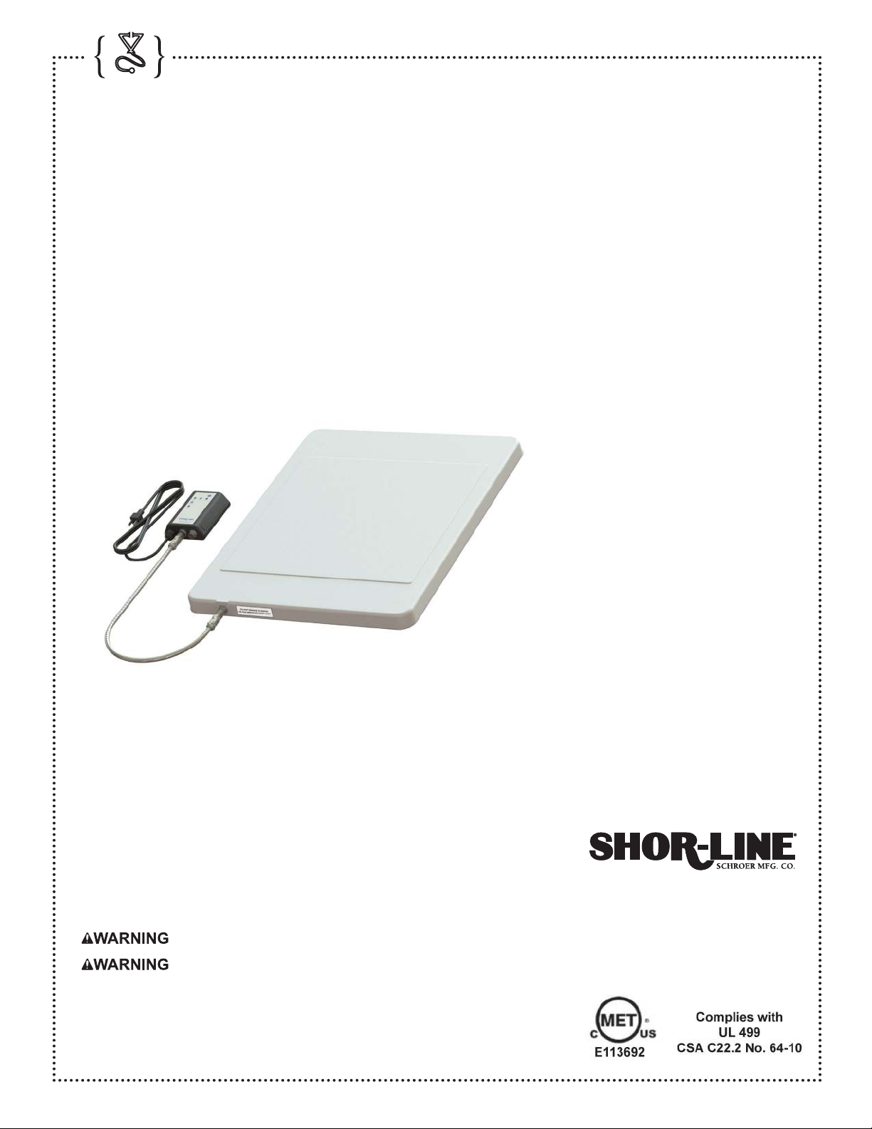
For best results place animal in the center of the Warming Pad.
• Read all instructions before using this equipment. Improper installation could cause product malfunction.
• This equipment must be grounded. Connect only to properly grounded outlet. See Grounding Instructions and
Installation below.
• Install or locate this equipment only in accordance with the provided installation instructions.
• Use this equipment only for its intended use as described in this guide.
• This equipment should not be used by children.
• Do not operate this equipment if it has a damaged cord or plug, if it is not working properly, or if it has been
dropped or damaged in any manner.
• Do not cover or block any opening on the equipment.
• Do not use outdoors.
• Do not use in an oxygen enriched environment or near oxygen emitting equipment.
• Do not immerse cord, plug or equipment in water.
• Do not let cord hang over edge of table or counter.
• Turn equipment off at switch before unplugging from wall outlet.
• When unplugging equipment, grip plug, not cord.
• Store equipment promptly after each use to prevent accidents from tripping over power cord or pulling equipment
off of work surface.
• Contact Shor-Line for examinations, repairs or adjustments.
{Grounding Instructions & Installation}
This equipment must be grounded. In the event of an electrical short circuit, grounding reduces the risk of electric
shock by providing an escape wire for the electric current. This equipment is equipped with a cord having a
grounding wire with a grounding plug. The plug must be plugged into an outlet that is properly installed and
grounded.
Improper use of the grounding plug can result in risk of
electric shock.
Consult a qualied electrician or service person if the grounding
instructions are not completely understood, or if doubt exists as to
whether the appliance is properly grounded.
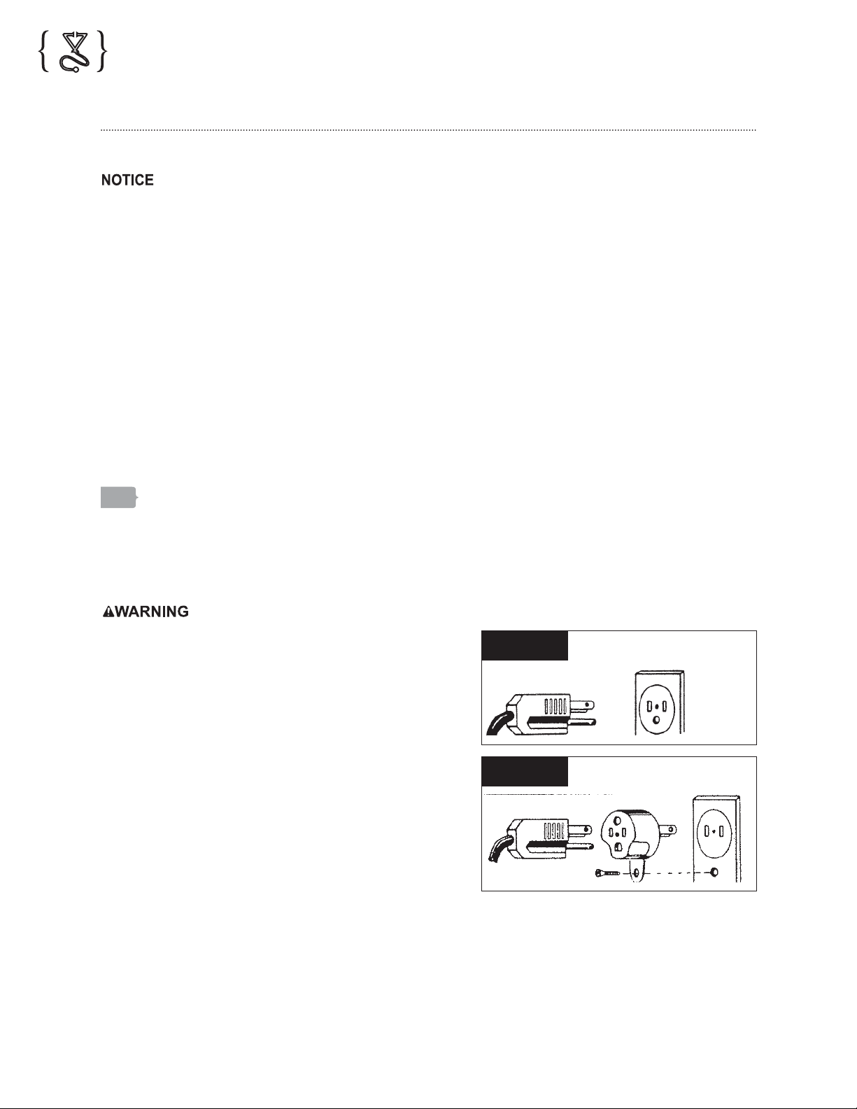
For personal safety, this equipment must be properly grounded
by being plugged directly into a 120 Volt, 50/60 Hz, or 240 Volt,
50/60 Hz (United Kingdom and Europe only), grounded polarized
three prong outlet (see voltage label on product). DO NOT, under
any circumstances, cut or remove the third (round) prong from the
power cord (Fig. 2.1).
The use of an extension cord, even a heavy duty cord, is not
recommended because of potential safety hazards.
Where a standard two-prong wall receptacle is encountered, it is
the personal responsibility and obligation of the consumer to have
it replaced with a properly grounded and polarized wall receptacle
in accordance with the National Electrical Code.
Where local codes permit, a TEMPORARY CONNECTION may be made to a properly grounded two-prong wall
receptacle by the use of an adapter which is available at most local hardware stores (Fig. 2.2).
Attaching the adapter ground terminal to the cover screw of the electric outlet, does not ground the equipment un-
less the cover screw is grounded through the building wiring. If there is any doubt whether the wall receptacle is
properly grounded, have it checked by a qualied electrician.
Fig. 2.2
Fig. 2.1

{7}
Shor-Line | 800.444.1579 | www.shor-line.com
;
Section 3: Warming Pad Assembly
{Assembly}
A minimal amount of assembly is required before using
your new Warming Pad. The Warming Pad is connected to
the control box using a 24” armored cable. The cable comes
factory installed on the Warming Pad and should not be
removed. See Fig. 3.1
Shor-Line Warming Pad Systems provide a warm
temperature-controlled bedding surface for small animals or
to assist in post-operative recovery. A towel may be placed
between the warming pad and the patient. Turn animals
routinely. Fractious animals should not be allowed access to
the Warming Pad without careful supervision because the
Warming Pad could be damaged.
The Warming Pad can be used by placing the unit under the
patient while lying on a table or placed inside a
Shor-Line 24 x 24"or larger cage.
NOTICE: Improper cable connections can cause product
malfunction. Failure to follow proper connection procedures
may result in a void of all Shor-Line warranties.
{Placing Unit in Cage}
Step 1
Ensure that the Warming Pad is not
connected to the controller.
Step 2
Place Warming Pad inside cage.
Step 3
Feed cable through the rods at the bottom left hand side of
the cage door. See Figure 3.2.
You are now ready to install the controller.
Fig. 3.2
ARMORED CABLE
WARMING PAD
DO NOT REMOVE
CABLE FROM PAD
Fig. 3.1

{8}
;
{Installing Warming Pad Controller}
IMPORTANT: Do not plug power cord into outlet until cables have been connected and controller has been mounted.
To establish communication between the Warming Pad and the controller, proper cable connection is a must. Each
time the Warming Pad is moved, either to a different cage or to a table, the cable will need to be disconnected and
reconnected.
NOTICE: Improper cable connections can cause product malfunction. Failure to follow proper connection procedures
may result in a void of all Shor-Line warranties.
{Cable Connection}
IMPORTANT: Do not bend the pins in the
connector. This will cause the product to
malfunction.
The Warming Pad is connected to the controller
using a steel armored cable with straight
multi-pin connectors and a bulkhead multi-
pin connector. The cable contains industry
standard alignment tools (Key and Key Way) to
assist you.
Once the Warming Pad cable has been
inserted through rods in the cage door, the
following steps should be taken to connect the
cable to the bulkhead connector
on the controller.
Step 1
Line up the Key and the Key Way.
NOTICE: If Key and Key Way are not aligned,
the pins may bend, making the unit inoperable.
Step 2
Gently push the two ends together.
NOTE: Do not force connection. If connectors
are aligned, cable will slip into place.
Step 3
Turn the nut clockwise to secure the connec-
tion.
NOTE: Do not secure until cable is in place, as
this could damage pins.
Fig. 3.3
CONTROLLER
POWER CORD
BULK HEAD
CONNECTOR
MOUNTING BRACKET
(BACK SIDE VIEW)
Fig. 3.4
CONTROLLER
POWER CORD
BULK HEAD
CONNECTOR
MOUNTING BRACKET
(BACK SIDE VIEW)

{9}
Shor-Line | 800.444.1579 | www.shor-line.com
;
{Cable Extension}
For those customers requiring additional space between the
Warming Pad and the Warming Pad Controller, the length
can be doubled by installing an additional cable. See Fig. 5.
Step 1
Disconnect cable attached to the controller.
Step
Connect the disconnected end of the existing cable to one
end of the additional cable. Then attach the other end to
the Warming Pad Controller as directed on page 7, Cable
Connection.
NOTE: This will increase the cable length to 48″. To
purchase additional armored cables, please call our
Technical Services Department at 800.444.1579.
{Mounting the Controller to the Cage Door}
NOTE: Do not plug in power cord until controller has been mounted.
Once the cable has been connected, you can mount the controller to the outside of the cage door using the
mounting bracket already attached to the back of the controller.
Step 1
Mounting bracket will attach to any of the horizontal rods on cage
door.
Step 2
To prevent damage to unit, do not bind cable when opening and
closing cage door.
Step 3
If controller is installed on the left side of the door, cable WILL
bind when closing the cage door, which may damage cable and
cause the unit to become inoperable. See Fig. 3.5.
Fig. 5
Fig. 3.5
IMPROPER MOUNTING

{10}
;
Step 4
For best results, install controller on the top rod on the right side of
the cage door. Placement here will allow the door to be opened and
closed without binding cable. See Fig. 3.6.
Step 5
Once controller has been mounted, plug power cord directly into
an outlet.
See Section 2: General Safety Precautions for Grounding
Instructions and Installation.
Your Warming Pad is now ready to use. See Section 4: Functions
for operating instructions.
{Moving Warming Pad}
The Warming Pad can be moved from one cage to another or dismantled for any reason using the following steps.
Step 1
Ensure the Warming Pad is powered off.
Step 2
Unplug power cord from outlet.
Step 3
Remove controller for cage door.
Step 4
Disconnect cable attached to the bulk head connector by turning counterclockwise.
NOTE: It is not necessary to remove controller or cable when opening and closing cage door to monitor patient.
Step 5
Remove Warming Pad from the cage by feeding the cable back through the rods at the bottom of the cage door.
NOTE: Warming Pad should be carried using the outer edges. Do not use cable.
Do not try to connect or disconnect the cable attached to the controller while the controller is
mounted to the cage.
Do not remove Warming Pad from cage or transport using the cable, as this could cause damage to
the Warming Pad.
Fig. 3.6
PROPER MOUNTING

{11}
Shor-Line | 800.444.1579 | www.shor-line.com
;
Section 4: Functions
• Power Button: Provides power to the Warming Pad controller
and selects the time cycle simply by the number of
times pressed.
• Press once: Will set the time for 60 minutes and the light
above ‘60 min’ on the control box will illuminate green.
• Press twice: Will set the time for 90 minutes and the light
above ‘90 min’ on the control box will illuminate green.
• Press three times: Will set the time for 120 minutes and the
light above ‘120 min’ on the control box will illuminate
green.
• Press four times: Will turn the controller off.
• Stand By: During the last ve minutes in any of the three
available time cycles the following will occur: For 4 minutes
the Stand By light will illuminate a solid yellow and a single
beep will occur every 30 seconds for a total of 8 beeps.
For the last minute of any time cycle the Stand By light will
illuminate a ashing yellow and a double beep will occur every
10 seconds.
• Alert: The Warming Pad is factory set at 93° F (33.8° C) with
an over temperature protection of 97° F (36.11° C).
If for any reason the pad reaches a temperature of 97° F
(36.11° C), the heater will be disabled, the alert light
will illuminate red and ash continuously and a triple beep
will occur. This condition will remain until the pad lowers
in temperature or the unit is turned off by pressing the
Power Button.
•NOTE: The Warming Pad is factory set to reach a temperature of 93° F (33.8° C) which takes approximately
15 minutes. Turning the unit off does not immediately reduce the temperature. Should the alert condition occur
the patient should be removed from the Warming Pad as soon as possible to prevent possible burns.
• Electrical Rating: 120/240 VAC, 50/60 HZ, .5A at 120 VAC, .25A at 240 VAC
Fig. 3
Power Button
Time Cycle Indicators
Stand By
Alert

{12}
;
Section 5: Maintenance & Cleaning
IMPORTANT: Do NOT immerse the Warming Pad in water or spray the controller box with water, cleaners,
sanitizer or disinfectants.
To clean the controller box:
Step 1
Unplug power cord.
Step 2
Disconnect the Warming Pad from the controller by unscrewing the cable from the bulk head connector counter
clockwise.
Step 3
The control box can then be wiped using a soft cloth dampened with sanitizer or disinfectant.
To clean the Warming Pad:
Step 1
Unplug power cord.
Step 2
Disconnect the Warming Pad from the controller by unscrewing the cable from the bulk head connector counter
clock wise.
Step 3
The Warming Pad may be wiped using warm soapy water or disinfectant on a soft damp cloth. Special care
should be taken to ensure the bulk head connectors are protected from uids during the cleaning process.
Section 6: Important
A towel may be placed between the warming pad and the patient. Fractious animals should not be allowed access to
the Warming Pad without careful supervision because the Warming Pad could be damaged.
Never permit access by any animal to the Warming Pad Power Cord.
Do not immerse Warming Pad assembly in water. Could result in dangerous electrical shock.
NOTICE: Improper cable connections can cause product malfunction. Failure to follow proper connection procedures
may result in a void of all Shor-Line warranties.

{13}
Shor-Line | 800.444.1579 | www.shor-line.com
;
Section 7: Services, Terms & Conditions, & Warranty
{Terms & Conditions}
ORDER & ACCEPTANCE By submitting an order for the products described herein, Buyer shall have agreed to
purchase the products subject to all Seller’s terms including these TERMS and CONDITIONS. Buyer’s order is
subject to and effective only upon acceptance and approval at Seller’s ofces in Kansas City, Kansas as evidenced
by Seller’s issuance of an Order Acknowledgement or Invoice. Processing of an order shall not commence until
receipt of any applicable deposit and all required paperwork and customer sign-offs. The resulting contract shall be
deemed made in Kansas and shall in all respects be governed and interpreted according to the laws of the State of
Kansas. Buyer also consents to the jurisdiction of Kansas courts over any dispute involving this order.
ENTIRE AGREEMENT This order as accepted and approved by Seller constitutes the entire nal agreement between
the parties. Except as otherwise provided in writing by Seller, the terms set forth herein constitute the sole TERMS
AND CONDITIONS for Buyer’s order. Seller’s acceptance of Buyer’s order is expressly conditioned on Buyer’s
assent to these TERMS AND CONDITIONS which may not be supplemented, modied, superseded or otherwise
altered except as authorized in writing by Seller. Any different, conicting or additional terms in Buyer’s purchase
order or any other document of Buyer are rejected and Seller’s TERMS AND CONDITIONS shall prevail.
TERMS OF PAYMENT Unless otherwise expressly specied by Seller in writing, payment shall be due 30 days from
the date of invoice, payable in U.S. Funds. Seller reserves the right to negotiate terms or orders of any unique or
special nature and may require full or partial payment in advance in its sole discretion. Acceptance of all orders and
the payment terms for such orders are subject to approval by Seller’s Credit Department. Seller may decline to make
any shipment or perform any work except upon terms satisfactory to said Department. A charge of 1½% per month
(or the highest monthly interest rate that may be imposed under applicable law) will be imposed on overdue accounts.
Buyer will be liable for all expenses (including reasonable attorneys’ fees) incurred in collecting any overdue
accounts.
PRICES & QUOTES Prices on products specied herein are F.O.B. Seller’s factory unless otherwise specied in
writing and are exclusive of any city, state, local or federal tax. Prices are subject to adjustment without notice and
Seller reserves the right to correct errors in prices or specications. Any quotation (whether written or oral) is not an
offer to contract or acceptance of an order. Similarly, neither a price list nor a catalog constitutes an offer to sell or
contract, but are provided solely for customers’ convenience.
TAXES Any sales, use, property, or other taxes or duties which Seller may be required to pay or collect (under any
existing or future law) in connection with the sale, purchase, delivery, storage, processing, consumption or use of the
products purchased herewith shall be for the account of Buyer and Buyer shall promptly reimburse Seller therefore.
DELIVERIES Delivery dates are estimates only and time shall not be of the essence unless specically provided by
Seller in writing. Seller will not have any liability for loss or damage resulting from a delay in a scheduled delivery or
for non-delivery resulting from labor trouble, part or material shortages, accident, re, war, strike, natural disaster,
carrier delays or any contingency whatsoever (whether of the same class of those enumerated or otherwise) beyond
its reasonable control. Buyer assumes all freight, handling and installation costs and the risk of loss or delay in transit.
Seller will assist Buyer with transit arrangements, but Seller shall be free of any liability in connection therewith. Title
to all materials and products sold by Seller shall pass to Buyer upon delivery to the carrier and Seller’s responsibility
ceases at that time. Risk of loss, injury, or destruction of the products shall be borne by the Buyer and any such loss,
injury or destruction shall not release Buyer from payment of the purchase price.
INSPECTION Buyer must inspect all materials for shortages, damages, conformity with order and defects before
signing any documentation requested by the carrier. Buyer must immediately complete such inspection and shall
not accept delivery of goods that are damaged or not in accordance with the bill of lading or packing slip without
proper notication to the carrier and Seller. If goods are damaged, defective, shorted or appear not to conform to
the order, Buyer shall discontinue their use and immediately notify the carrier and Seller of such condition and afford
a reasonable opportunity to inspect the same. Buyer shall make, or provide Seller in writing with all information
necessary to make, a claim against such carrier for any shortage, damage, or discrepancy of the shipment within
fteen (15) days after receipt of the goods. Claims or written information thereon not so presented within fteen (15)
days after receipt of the goods will not be allowed. No products will be taken back and credited or replaced unless
arrangements for their return have been made in compliance with Seller’s Return Policy stated below.
SEE SELLER’S CATALOG FOR INFORMATION ON HOW TO FILE A FREIGHT CLAIM.

{14}
;
PRODUCT SATISFACTION In the event Buyer is not fully satised with the quality or workmanship of a product
purchased hereunder, Seller in its sole discretion may arrange either to credit Seller’s account (excluding shipping
and handling costs) or replace the product. However, Buyer must notify Seller in writing of its dissatisfaction within
fteen (15) days of receipt of the product from Seller and immediately discontinue its use. Buyer also must return the
rejected product to Seller freight paid within thirty (30) days of its receipt in compliance with Seller’s Return Policy
stated below. Seller’s obligation is limited to providing the applicable credit or product replacement, which will be
processed only after receipt of the retuned product. In addition, this Product Satisfaction policy does not apply to
specially designed, discontinued, used, factory second or repaired products.
LIMITED WARRANTY Seller warrants to the initial purchaser only of products manufactured by it that such products
are free from defects in materials or labor for varying periods depending on the particular product and subject to
the limitations and conditions set forth herein. Seller’s stainless steel products are warranted to be free from such
defects for their normal useful life. Seller’s mechanical and electrical products, parts, devices and components
(including such parts, devices and components of stainless steel products), and other-non-stainless steel products
are warranted to be free from such defects for only one year. Seller disclaims any express or implied warranty for
products not manufactured by Seller and the only warranty available therefore to Buyer is that offered by the products’
manufacturers.
The warranty period shall run from the date of delivery to Buyer. If within the applicable warranty period a product
proves to be defective as described herein, Seller will repair or replace the product, at Seller’s sole discretion,
conditional upon Buyer’s written notice of the defect within fteen (15) days after its discovery. Upon receipt of
Buyer’s notice including substantiation of Buyer’s status as the initial purchaser and details of the defect, Seller
shall advise Buyer whether it plans to repair or replace the product. Seller’s obligation is solely limited to repair or
replacement of a defective product and in no event shall Seller be liable for transportation from or to Seller’s ofces
or any other expense which may arise in connection with this Limited Warranty or the aforementioned Product
Satisfaction policy.
SELLER MAKES NO OTHER WARRANTY OR GUARANTEE OF ANY KIND WHATSOEVER, WHETHER EXPRESS
OR IMPLIED, STATUTORY OR OTHERWISE INCLUDING, BUT NOT LIMITED TO IMPLIED WARRANTIES OF
FITNESS, AND/OR MERCHANTABILITY. THE ABOVE LIMITED WARRANTY CONSTITUTES SELLER’S ONLY
WARRANTY AND NO PERSON OR ENTITY IS AUTHORIZED, ON BEHALF OF THE SELLER, TO MODIFY OR
EXPAND UPON THE PROVISION EXPRESSED IN THIS PARAGRAPH NUMBER NINE. THE SELLER’S LIABILITY
UNDER THIS LIMITED WARRANTY SHALL BE LIMITED AS PROVIDED FOR ABOVE AND THE FOREGOING
SHALL BE THE BUYER’S SOLE REMEDY AND RECOURSE UNDER THIS CONTRACT. There are no warranties
which extend beyond the description on the face hereof and goods are sold as is. Seller’s Limited Warranty is only
available to the initial purchaser of its products and is effective only upon compliance with the terms set forth herein.
Buyer agrees that the products subject to this Limited Warranty will be properly maintained in the ordinary course
of business. Buyer agrees to comply with all instructions and specications furnished by Seller relating to the
installation, care, use and application of products purchased. Buyer agrees that it will not modify, misapply, or misuse
such products in any manner which would deviate from Seller’s instructions. Any repairs, alterations or service
provided by parties other than Seller, or its authorized representative, may void this Limited Warranty. This Limited
Warranty shall not apply to normal wear and tear, improper or insufcient maintenance, routine maintenance, or
damage caused by accident, negligence, improper operation or the use of corrosive materials (including without
limitation bleach or sodium hypochlorite used on stainless steel surfaces). THE SELLER’S LIMITED WARRANTY
MADE IN CONNECTION WITH THIS SALE SHALL NOT BE EFFECTIVE AND SHALL BE VOID UNLESS SUCH
GOODS ARE APPLIED AND USED IN ACCORDANCE WITH SELLER’S INSTRUCTIONS.
LIMITATION OF LIABILITY UNDER NO CIRCUMSTANCES SHALL SELLER BE LIABLE TO BUYER OR
ANY OTHER PERSON FOR ANY SPECIAL, LIQUIDATED, INCIDENTAL OR CONSEQUENTIAL DAMAGES,
INCLUDING, WITHOUT LIMITATION, DAMAGES BASED UPON LOST GOODWILL, LOST SALES OR PROFITS,
WORK STOPPAGE, DELAY, PRODUCT FAILURE, IMPAIRMENT OF GOODS OR OTHERWISE AND WHETHER
ARISING OUT OF BREACH OF WARRANTY, BREACH OF CONTRACT, NEGLIGENCE OR OTHERWISE, and
in any case, Seller’s liability for any and all losses and damages sustained by Buyer and others, rising out of or by
reason of this contract, shall not exceed the original purchase price of the products upon which liability is founded.
IN NO EVENT SHALL ANY ACTION BE COMMENCED AGAINST THE SELLER MORE THAN ONE YEAR AFTER
THE CAUSE OF ACTION WITH RESPECT TO WHICH THE CLAIM IS MADE HAS ACCRUED. SELLER SHALL
NOT BE RESPONSIBLE FOR EXPENSES FOR REPAIRS NOT MADE BY SELLER WITHOUT THE PRIOR
WRITTEN CONSENT OF SELLER.

{15}
Shor-Line | 800.444.1579 | www.shor-line.com
;
RETURN POLICY All products being returned for any reason or delivered for repair service (whether or not pursuant
to our Limited Warranty) must receive advance authorization from Seller. Buyer must contact Seller’s Technical
Service Department at 1.800.444.1579 to receive a Return Authorization Number. All products returned, except for
warranty service or pursuant to the Product Satisfaction policy, are subject to a minimum 15% restocking charge.
Buyer will be responsible for all freight charges on returns.
INDEMNITY Buyer agrees to protect, defend, indemnify and hold harmless the Seller from and against any and all
direct loss suffered and any liability to third parties due to bodily injury (including death) to any person or animal, or
damage to any property as a result of Buyer’s misuse, misapplication or failure to inspect or maintain the Seller’s
products, or such loss or liability caused by the act or omission of the Buyer in the performance of any services
using said products. Buyer also agrees to indemnify and hold harmless the Seller for any taxes paid as discussed
in paragraph ve above. This indemnity provision expressly includes attorney’s fees and settlements of claims in a
reasonable manner under the circumstances.
UNLAWFUL USE Buyer agrees that no goods covered by this contract shall be used in any manner violative of any
laws of the United States, whether state or federal, or local ordinance, and no such goods shall be distributed to any
foreign country in any manner prohibited by United States law.
REGULATIONS AND CODES Seller makes no representation or promise, express or implied, that goods delivered
hereunder will conform to any state or local laws, regulations, codes, ordinances, or standards, except as particularly
and expressly specied and agreed upon for compliance in writing as a part of the contract between Buyer and Seller.
SELLER’S REMEDIES Seller hereby expressly reserves all remedies provided for by the Uniform Commercial Code
and such remedies are expressly cumulative in nature and include all of the available remedies for breach and Seller
need not make any election of remedy.
MISCELLANEOUS Buyer may not assign its rights or duties relative to this order without Seller’s written consent,
but Seller may assign its interest in such order to any afliate or successor in interest. The waiver of any breach of
these TERMS AND CONDITIONS shall not constitute a waiver as to any further breach. Any of these TERMS AND
CONDITIONS found to be invalid, illegal or unenforceable, shall be considered inoperative and the remaining TERMS
AND CONDITIONS shall be valid and enforceable as though such provisions are not included herein. Contact our
Credit Department toll-free for questions at 800.444.1579.

Shor-Line/Schroer Manufacturing Co.
511 Osage Avenue
Kansas City, KS 66105 U.S.A.
800
444.1579
toll free local fax
913
281.1500 913
281.5339
www.shor-line.com
{
{
This manual suits for next models
4
Table of contents