manuals.online logo
Brands
  1. Home
  2. •
  3. Brands
  4. •
  5. SHORE TEL
  6. •
  7. Switch
  8. •
  9. SHORE TEL ShoreGear-T1 User manual

SHORE TEL ShoreGear-T1 User manual

Other SHORE TEL Switch manuals

SHORE TEL ST50A User manual

SHORE TEL

SHORE TEL ST50A User manual

SHORE TEL ShoreGear 90BRI User manual

SHORE TEL

SHORE TEL ShoreGear 90BRI User manual

SHORE TEL ShoreGear 90BRIV User manual

SHORE TEL

SHORE TEL ShoreGear 90BRIV User manual

SHORE TEL 200 User manual

SHORE TEL

SHORE TEL 200 User manual

SHORE TEL SG-220T1 User manual

SHORE TEL

SHORE TEL SG-220T1 User manual

SHORE TEL ShoreGear-60/12 User manual

SHORE TEL

SHORE TEL ShoreGear-60/12 User manual

SHORE TEL ShoreGear 220T1A User manual

SHORE TEL

SHORE TEL ShoreGear 220T1A User manual

SHORE TEL SG-120 User manual

SHORE TEL

SHORE TEL SG-120 User manual

SHORE TEL ShoreGear 30 User manual

SHORE TEL

SHORE TEL ShoreGear 30 User manual

SHORE TEL ST100DA User manual

SHORE TEL

SHORE TEL ST100DA User manual

SHORE TEL ST1D User manual

SHORE TEL

SHORE TEL ST1D User manual

SHORE TEL Extreme Summit x440 Series User manual

SHORE TEL

SHORE TEL Extreme Summit x440 Series User manual

SHORE TEL ShoreGear 90BRI User manual

SHORE TEL

SHORE TEL ShoreGear 90BRI User manual

Popular Switch manuals by other brands

SMC Networks SMC6224M Technical specifications

SMC Networks

SMC Networks SMC6224M Technical specifications

Aeotec ZWA003-S operating manual

Aeotec

Aeotec ZWA003-S operating manual

TRENDnet TK-209i Quick installation guide

TRENDnet

TRENDnet TK-209i Quick installation guide

Planet FGSW-2022VHP user manual

Planet

Planet FGSW-2022VHP user manual

Avocent AutoView 2000  AV2000BC AV2000BC Installer/user guide

Avocent

Avocent AutoView 2000 AV2000BC AV2000BC Installer/user guide

Moxa Technologies PT-7728 Series user manual

Moxa Technologies

Moxa Technologies PT-7728 Series user manual

Intos Electronic inLine 35392I operating instructions

Intos Electronic

Intos Electronic inLine 35392I operating instructions

Cisco Catalyst 3560-X-24T Technical specifications

Cisco

Cisco Catalyst 3560-X-24T Technical specifications

Asante IntraCore IC3648 Specifications

Asante

Asante IntraCore IC3648 Specifications

Siemens SIRIUS 3SE7310-1AE Series Original operating instructions

Siemens

Siemens SIRIUS 3SE7310-1AE Series Original operating instructions

Edge-Core DCS520 quick start guide

Edge-Core

Edge-Core DCS520 quick start guide

RGBLE S00203 user manual

RGBLE

RGBLE S00203 user manual

Thrustmaster FLIGHT SIMULATOR X quick guide

Thrustmaster

Thrustmaster FLIGHT SIMULATOR X quick guide

Southwire SURGE GUARD 41390 RVC troubleshooting guide

Southwire

Southwire SURGE GUARD 41390 RVC troubleshooting guide

Buhler Nivotemp NT 61 Brief instructions

Buhler

Buhler Nivotemp NT 61 Brief instructions

Kramer VS-41HDCP user manual

Kramer

Kramer VS-41HDCP user manual

Techly IDATA AU-270 user manual

Techly

Techly IDATA AU-270 user manual

Belkin F1U109 user manual

Belkin

Belkin F1U109 user manual

manuals.online logo
manuals.online logoBrands
  • About & Mission
  • Contact us
  • Privacy Policy
  • Terms and Conditions

Copyright 2025 Manuals.Online. All Rights Reserved.

Choosing a Location
To ensure optimum operating conditions for the ShoreGear voice switch, make
sure that its operating environment is adequately ventilated, free of gas or airborne
particles, and isolated from electrical noise.
Installing the ShoreGear Voice Switch (Rack Mount)
The ShoreGear voice switch is equipped with pre-installed rack-mount ears for easy
installation into a standard 19-inch rack.
Introduction
About The ShoreGear-T1
The ShoreGear-T1 Voice Switch is an IP-based Private Branch Exchange (IPBX)
that connects internal extensions to an central office (CO) analog trunk line.
The switch provides connectivity through:
• two RJ-45 LAN connectors
• one RJ-45 T1 port for connecting the switch to a telephone company line
• one RJ-45 T1 monitor port for connecting test equipment
• one DB-9, RS-232C maintenance port (19200 bps, 8 bits, no parity, 1 stop bit,
no handshake) for serial communications
The ShoreGear-T1 Voice Switch package contains:
• ShoreGear-T1 Voice Switch
• a power cord
• stick-on feet (for surface installation)
Installation
1 Lift the ShoreGear voice switch
to the desired height and
attach it to the frame with four
standard rack screws.
2 Insert the screws in both the
upper and lower positions on
the rack-mount ears.
ShoreGear
-
T1
What You Need for Installation
To install the switch, you need the following equipment:
• AC surge protector for the power connection
• RJ-45 cable for connecting the switch to the local area network and telco lines
• #1 Phillips screwdriver
Connections
NOTE: Make sure there is at least
two inches of open space around all vent holes.
Mounting the ShoreGear Voice Switch on a Flat Surface
If you plan to mount the switch on a flat surface, first attach the provided rubber feet
to the bottom corners of the device. (You can stack up to three switches in a surface
installation.)
Powering on the ShoreGear Voice Switch
After connecting the switch to the network, power on the device by connecting it to
an AC power source.
1 Plug an AC surge protector (not provided) into a grounded AC power source.
2 Plug one end of the provided power cord into the receptacle on the back of the
switch, then plug the other end into the AC surge protector.
The power LED flashes momentarily, and remains lit.
• If the LED is not lit, make sure the power cord is plugged into the switch and the
power source.
• If the LED continues flashing, there is an internal error. Unplug the switch to
power it off, then power it back on. Refer to the “Configuring Switches” chapter
in the ShoreTel Administration Guide for information on flash patterns, or contact
the ShoreTel Customer Response Center at http://www.shoretel.com.
The LAN ports auto-sense the network transport rate. When the network
connection is established, the network LED indicates a transport rate of 10 Mbps or
100 Mbps, and whether the switch is receiving and transmitting data.
Connecting Trunk and Telephone Lines
After setting up the network connections and configuring the ShoreGear T1 Voice
Connecting the ShoreGear Voice Switch to the Network
Once the ShoreGear-T1 Voice Switch is secured to a rack or surface-mounted, you
can connect it to the data network.
Switch for operations, you can connect your
T1 line to the switch.
• Use an RJ-45 T1 cable to connect your T1
line to the Telco port.
NOTE: For detailed information on switch
port and trunk configuration, see the sections
“Configuring Switches” and “Configuring Trunks”
in the ShoreTel Administration Guide.
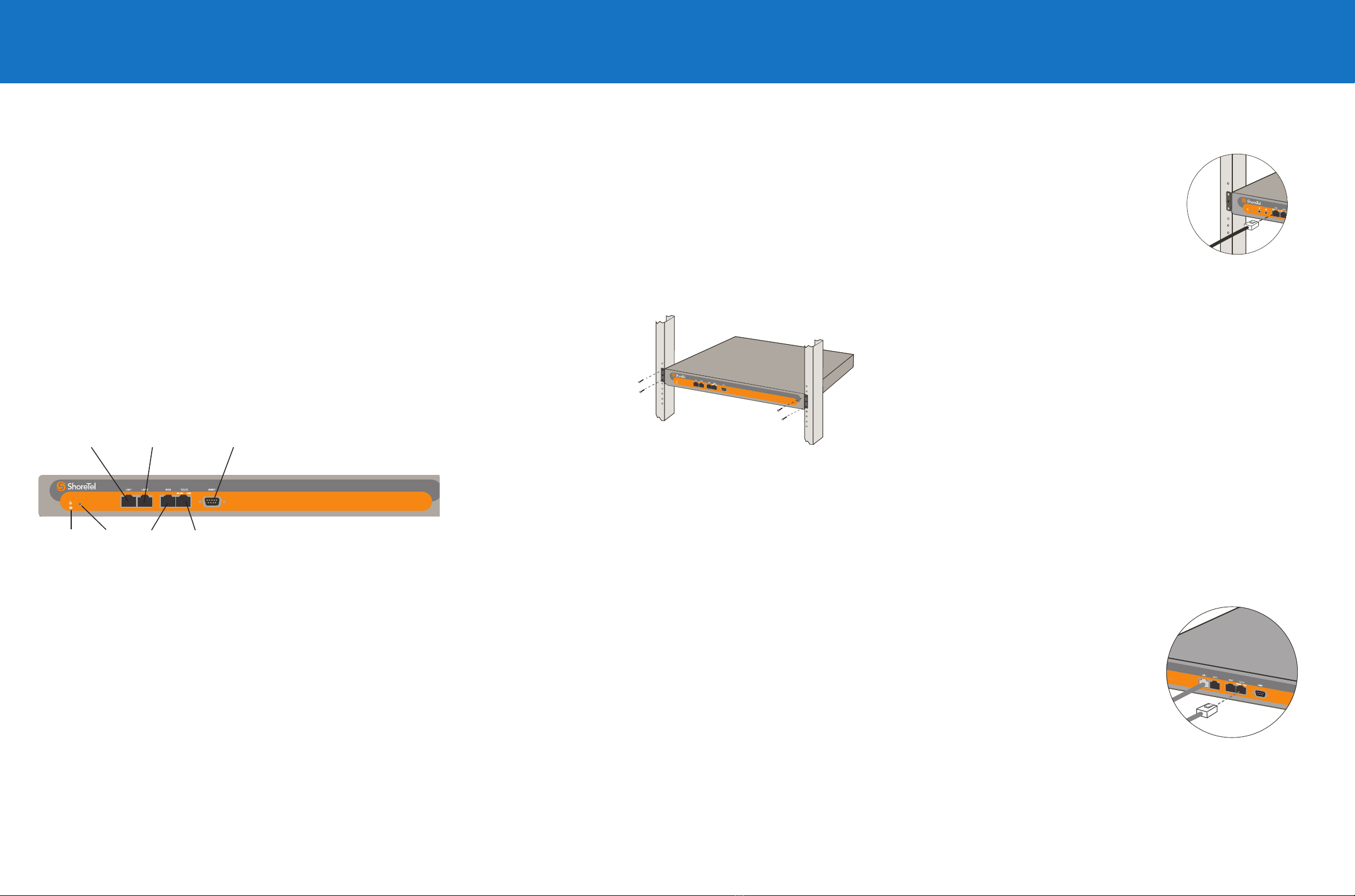
ShoreGear-T1
Power LED
LAN 2 Connector
RS-232C
maintenance port
Digital trunk
telco port
LAN 1 Connector
Monitor
port
• Use an RJ-45 Ethernet cable to connect one or
both of the LAN ports to the network.
NOTE: While both ports can detect and respond to link
status, the switch uses only one LAN port at a time.
Default
switch
Power LED
The power LED indicates the operating status of the switch.
Light Description
Steady The switch is powered on, and the internal software is running.
Flashing Two fl ashes indicates a failed internal self-test (i.e. hardware failure). Refer to
“Confi guring Switches” in the ShoreTel Administration Guide for details on other
fl ash patterns.
Off The switch is not powered on, or the software is not running.
Network LEDs
The ShoreGear-T1 network LED lights provide information on network communications
speed and network activity.
LED Color/State Description
Link/Act Off This switch cannot detect an Ethernet network.
Link/Act Green-Steady This switch is connected to an Ethernet network.
Link/Act Green-Flashing This switch detects network data traffi c.
10/100 Off Network interface is operating at 10 Mbps.
10/100 Green Network interface is operating at 100 Mbps.
T1 LEDs
The voice switch’s T1 LED lights provide information about line coding, network framing,
and loopback status.
LED Color/State Description
Line coding Green The AMI or B8ZS line coding signal is good.
Line coding Yellow This switch is receiving bipolar violations (BPV) at one-second
intervals.
Line coding Red A loss of signal (LOS) has occurred.
Line coding Off The switch has no power.
Framing Green The T1 signal is in frame (synchronized)
Framing Yellow The CO has sent a yellow alarm.
Framing Yellow (Flashing) The frame-bit error rate has exceeded its limits
Framing Red T1 signal is out-of-frame (OOF) and cannot be framed to the
Extended Superframe (ESF) or D4 format.
Framing Off The switch has no power.
LC/Framing Red (Flashing) Loopback is enabled. (You can set loopback from Shoreline
Director, or it can be set at the CO.)
Confi guration & Specifi cations
Network Confi guration
Once the ShoreGear voice switch is installed and powered on, it must be confi gured
for network operations. A voice switch gets a network confi guration by assignment
from a DHCP or BOOTP server, or directly from an administrator console (see
procedure below).
NOTE: For more information on setting up a switch for automatic confi guration by a
DHCP or BOOTP server, see the ShoreTel Planning and Installation Guide.
Confi guring the Voice Switch from a Console
1 Use a straight-through serial cable to connect the switch to a console PC.
2 On the PC or laptop, start a terminal emulation program and connect to the
voice switch using these serial communication settings: 19200 bps, 8 data bits,
no parity, one stop bit, no handshake.
3 At the ShoreTel login prompt, press ENTER to display the Switch Options
menu.
4 Type 3 and press ENTER to display a menu of confi guration options.
5 Choose Menu Options and follow the onscreen instructions for setting network
parameters, including IP address, subnet mask, and gateway.
Specifi cations
Feature Specifi cation
Dimensions 1.72 x 17.16 x 14.28 inches (43.68 x 435.86 x 362.71 mm)
Weight 9 lb (4.08 kg)
Input voltage 100-240 VAC, 50-60 Hz
Power consumption 1A max.
Humidity 0-90% relative humidity (non-condensing)
Operating temperature 0-50˚ C
Connection & Power
Switch Status
Quick Install Guide
ShoreGear-T1 Voice Switch
TM
Copyright © 2006 ShoreTel. All rights reserved. ShoreTel, the ShoreTel logo, ShoreGear,
ShoreWare, and ShorePhone are trademarks of ShoreTel, Inc. in the United States and/or other
countries. All specifi cations are subject to change without notice.
PN 800-1012-03
960 Stewart Drive Sunnyvale, California 94085
Phone: 408-331-3300 OR 1-800-425-9385 Fax: 408-331-3333 www.shoretel.com