Introduction
About the ShoreGear 90BRIV
The SG-90BRIV Voice Switch connects enterprise telephone extensions through an
internal IP network, or to any central office (CO) ISDN BRI trunk line. The switch
provides connectivity through:
• Two RJ-45 local area network (LAN) connectors
• Four RJ-45 ISDN BRI ports for connecting the switch to telephone company ISDN
BRI lines
• One RJ-21X port (male) for connecting the switch to a telephone company punch-
down block, patch panel, or 12-port harmonica connector
• One DB-9 (female), RS-232C maintenance port (19200 bps, 8 bits, no parity, 1 stop
bit, no handshake) for serial communications
• One audio input port (3.5 mm stereo) for connecting to a music-on-hold source
• One audio output port (3.5 mm stereo) for connecting to a corporate paging system
or night bell
The ShoreGear 90BRIV Voice Switch package contains:
• ShoreGear 90BRIV Voice Switch
• Power cord
• Stick-on feet for surface installation
• Mounting Ears – attachable installation brackets
• Cable retainer for the Telco cable (metal bracket with a Velcro strap)
Installation Connections and Servicing
Mounting the ShoreGear Voice Switch on a Flat Surface
If you plan to mount the switch on a flat surface, first attach the provided rubber feet
to the bottom corners of the device. You can stack up to three switches in a surface
installation.
Installing the ShoreGear 90BRIV in a 19-inch Rack
The SG-90BRIV is placed in a 19-inch rack only by mounting a ShoreGear Dual Tray
into the rack, then installing the SG-90BRIV into the Tray.
Refer to the Quick Install Guide for the ShoreGear Dual Tray for Tray installation
instructions and information on using the Tray.
Connecting Trunk and Telephone Lines
Optional Connections
Powering on the ShoreGear Voice Switch
After connecting the switch to the network, power on the device by connecting it to an AC
power source.
1. Plug an AC surge protector (not provided) into a grounded AC power source.
2. Plug one end of the provided power cord into the receptacle on the back of the switch, then
plug the other end into the AC surge protector.
The power LED flashes momentarily, and remains lit.
• If the LED is not lit, make sure the power cord is plugged into the switch and the power
source.
• If the LED continues flashing, there is an internal error. Unplug the switch to power it
off, then power it back on. Refer to the “Configuring Switches” chapter in the ShoreTel
Administration Guide for information on flash patterns, or contact the ShoreTel Support
Services at http://www.shoretel.com.
The LAN ports auto-sense the network transport rate. When the network connection is
established, the network LED indicates a transport rate of 10 Mbps or 100 Mbps, and whether
the switch is receiving and transmitting data.
Once the ShoreGear 90BRIV Voice Switch is secured to a rack or surface-
mounted, you can connect it to the data network. Use an RJ-45 Ethernet cable to
connect one or both of the LAN ports to the network subnet.
While both ports can detect and respond to link status, the switch uses only one
LAN port at a time.
German: Einen Erdungsleiter anschließen
Um den elektrischen Sicherheitsanforderungen für eine korrekte Erdung
nachzukommen, müssen Sie einen permanenten Erdungsschutz zwischen dem
ShoreGear-Gerät und der Erde des Kabelsystems installieren.
1. Schließen Sie ein Erdungskabel (Nr. 14 AWG oder größer) an die Schraube an der
Rückseite des Geräts an, die sich rechts neben dem Produktetikett befindet.
2. Schließen Sie das andere Ende des Erdungskabels an die Erde des Kabelsystems an.
VORSICHT: Schließen Sie immer zuerst den permanenten Erdungsschutz an, bevor Sie ver-
suchen, das Gerät an ein LAN-Segment und Telekommunikationsleitungen anzuschließen.
Connecting the ShoreGear Voice Switch to the Network
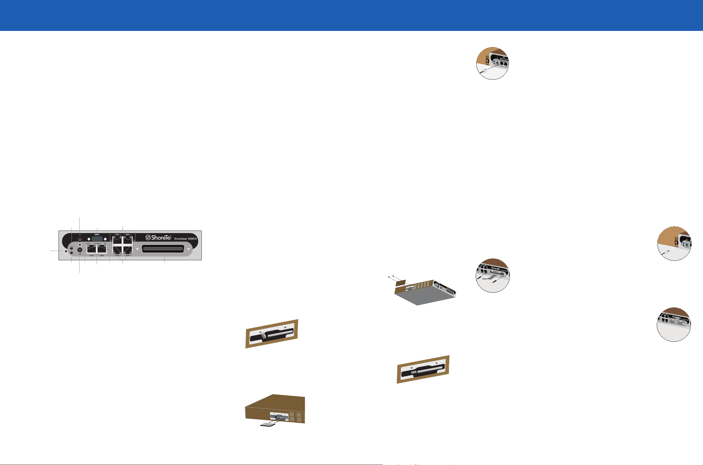
Default
Switch
Audio Output Port
(night bell)
Power
LED
Network
LEDs
RS-232C
Maintentance
Port
RJ-21X
Telco Port
Status
LED
Audio Input Port
(music on hold)
Network
LEDs LAN
Connectors
BRI
LEDs
BRI
LEDs
BRI
Ports
BRI
Ports
Installation Equipment
To install the switch, you need the following equipment:
• AC surge protector for the power connection
• RJ-45 cables for connecting the switch to the local area network and telco lines
• Music-on-hold source with a standard mini-headphone Y-adapter (optional)
• Permanent earthing connector for grounding the device
• RJ-21 telephone cable (female on end connected to ShoreGear voice switch) for
analog port connections
• RJ-21 to RJ-11 patch panel for connecting telephones and trunk lines
• #1 Phillips screwdriver
Installation Location Requirements
To ensure optimum operating conditions for the SG-90BRIV voice switch, verify the
operating environment is adequately ventilated, free of gas or airborne particles, and
isolated from electrical noise.
Use the provided cable retainer to connect the voice switch to the telephone
company’s punch-down block or patch panel.
1. Use a #1 Phillips screwdriver to remove the two screws on either side of the
RJ-21X port, then place the retainer on the port and re-attach the screws.
2. Plug the Telco cable into the port, then pull the Velcro strap tightly around
the cable connector and fasten it.
3. Connect the other end of the Telco cable to the punch-down block or patch
panel.
4. Use RJ-45 cables to connect your ISDN BRI lines to the telco ports.
CAUTION: To reduce risk of re, use only No. 26 AWG or larger (e.g., 24
AWG) UL Listed or CSA Certied Telecommunication Line Cord
VORSICHT: Um das Brandrisiko zu verringern, verwenden Sie nur Tele-
kommunikationsleitungen Nr. 26 AWG oder größer (z.B. 24 AWG) mit UL-
oder CSA-Zulassung
For detailed information on switch port and trunk conguration, see the “Conguring
Switches” and “Conguring Trunks” sections in the ShoreTel Administration Guide.
After connecting the voice switch to the LAN, you can make optional
connections, including input from a music-on-hold source or output to an
internal paging system.
1. Connect a music-on-hold source (CD player or other audio source) to the
audio input port.
2. Connect your site’s paging system to the audio output port.
German: Das ShoreGear Voice-Schaltgerät auf einer ebenen
Oberäche montieren
Wenn Sie planen, das Gerät auf einer ebenen Oberfläche zu montieren, befestigen Sie
zunächst die mitgelieferten Gummifüße an den unteren Ecken des Geräts. (Bei einer
Oberflächeninstallation können Sie bis zu drei Schaltgeräte übereinander stapeln.)
Attaching an Earthing Connector
To meet electrical safety requirements for proper grounding, you must connect a
permanent earthing protector between the ShoreGear voice switch and the wiring
system ground.
1. Connect a ground wire (#14 AWG wire or larger) to the screw on the back of the
unit and to the right of the product label.
2. Connect the other end of the ground wire to the wiring system ground.
CAUTION: Always connect the permanent earthing connector before attempting to connect
the switch to a LAN segment and telecommunication lines.
Installing a Compact Flash Card
Accessing the Compact Flash Card
1. Unplug power from the switch.
2. Disconnect all cables and grounding wires.
3. If in a Dual Tray, remove it from the tray.
4. Remove the Compact Flash cover by extracting the two
screws holding the cover to the left panel of the switch.
Changing the Compact Flash Card
1. Pivot the button to Out position with a finger or pen.
2. Push the button to eject the Compact Flash card.
3. Pull the card to remove it from the unit.
Reinstalling the Voice Switch
1. Place the Compact Flash cover on the left panel, using
the two screws to secure the cover.
2. Reconnect all cables and grounding wires to the switch.
3. Return the switch to its previous installation
configuration. Plug power into the switch.
CAUTION: The cover and screws must be in place to protect against hazardous voltages!
VORSICHT: Die Abdeckung und die Schrauben müssen zum Schutz vor gefährlicher Span-
nung unbedingt eingesetzt werden!
Button – Out
4. Push a new card into the unit until it is securely seated.
The button pops out when the card is seated.
5. Return the button to Flat position by pulling it outward,
then pivoting it left. Servicing Procedures
WARNING: The SG-90BRIV contains no internal field serviceable parts except for the Compact
Flash Card. Return the equipment to ShoreTel for any required service procedures.
CAUTION: Internal fuses should be serviced only by qualified ShoreTel personnel. If internal
fuses are blown and require replacement, return the SG-90BRIV to ShoreTel for service.
WARTUNGSVERFAHREN
ACHTUNG: Die Produkte SG-90BRIV enthalten keine internen Teile, die vor Ort gewartet
werden können mit Ausnahme der Compact Flash Card. Senden Sie das Gerät an ShoreTel, falls
Wartungsarbeiten erforderlich sein sollten.
VORSICHT: Interne Sicherungen dürfen nur von qualifizierten ShoreTel-Mitarbeitern gewartet
werden. Wenn interne Sicherungen ausgetauscht werden müssen, senden Sie den SG-90BRIV
zur Wartung an ShoreTel.


