ShotSpotter Gunshot Location System User manual

1
1
August 31, 2008
Initial Draft
Document Number: 630-0028-01 Rev A
ShotSpotter®Gunshot
Location System
Sensor Installation
Guide

ShotSpotter Sensor Installation Guide
2
Copyrights
©2008 ShotSpotter, Inc. All rights reserved. U.S. Patent Nos. 5,973,998; 6,847,587;
7,139,222; 7,266,045; and other foreign and domestic patents pending. ShotSpotter Gun
Location and Detection System® is a registered trademark of, and the ShotSpotter logo
is a trademark of ShotSpotter, Inc. All other company and product names mentioned
herein may be trademarks of their respective companies.
All title and copyrights in and to the DOCUMENTATION (including but not limited to all
images, photographs, text, and other information incorporated into the
DOCUMENTATION), the accompanying printed materials, and any copies of the
DOCUMENTATION, are owned by ShotSpotter, Inc.
The DOCUMENTATION is protected by copyright laws and international treaty
provisions. Accordingly, the Customer is required to treat the DOCUMENTATION like
any other copyrighted material, except as otherwise allowed pursuant to their LICENSE
AGREEMENT with ShotSpotter, Inc. Customers may make and distribute copies of the
DOCUMENTATION solely for their internal use as well as for backup or archive
purposes. The DOCUMENTATION should not be distributed beyond the Customer’s
employees and contractors or in any way made publicly available without the express
written consent from ShotSpotter.
You can find copyright information in the About ShotSpotter on the File menu bar under
Help on the Main Window in the “ShotSpotter GLS User’s Guide”.
Windows XP® operating system and Windows® are registered trademarks of Microsoft
Corporation in the United States and other countries.
Statement of Conditions
NOTE: Some screenshots for the Radio Diagnostic Tool in this Guide have been
redacted to protect private information.
Information in this document is subject to change without notice.
WARNING: Changes or modifications to the installation instructions given in this
manual, including opening of equipment, not expressly approved by ShotSpotter
Inc. will void system maintenance and support, and could void the user's
authority to operate the equipment.
Electronic Emission Notices
This device complies with part 15 of the FCC Rules.
Operation is subject to the following two conditions:

ShotSpotter Sensor Installation Guide
3
(1) This device may not cause harmful interference.
(2) This device must accept any interference received, including interference that
may cause undesired operation.
FCC Radio Frequency Interference Statement
The sensor with integrated radio equipment has been tested and found to comply
with the limits for a Class A digital device, pursuant to part 15 of the FCC Rules.
These limits are designed to provide reasonable protection against harmful
interference when the equipment is operated in a commercial environment. This
equipment generates, uses, and can radiate radio frequency energy and, if not
installed and used in accordance with the instruction manual, may cause harmful
interference to radio communications. Operation of this equipment in a residential
area is likely to cause harmful interference in which case the user will be required
to correct the interference at the user’s own expense.

ShotSpotter Sensor Installation Guide
4
Contents
COPYRIGHTS................................................................................................................................. 2
STATEMENT OF CONDITIONS ........................................................ERROR!BOOKMARK NOT DEFINED.
CONTENTS..................................................................................................................................... 4
INTRODUCING THE SHOTSPOTTER GLS SYSTEM................................................................... 5
OVERVIEW ..................................................................................................................................... 5
BENEFITS....................................................................................................................................... 5
SHOTSPOTTER GLS SYSTEM COMPONENTS................................................................................... 6
HOW DOES THE SHOTSPOTTER GLS WORK?......................................................................... 7
SYSTEM PERFORMANCE AND ACCURACY.............................................................................. 7
INSTALLING THE WIRELESS SENSOR....................................................................................... 8
OVERVIEW .................................................................................................................................... 8
WIRELESS SENSOR COMPONENTS ................................................................................................. 8
INSTALLING A WIRELESS SENSOR - BACKGROUND.............................................................. 9
VISUALLY INSPECTION WHEN RECEIVING NEW EQUIPMENT FROM FACTORY...................................... 9
Inspect the Acoustic Sensor ................................................................................................... 9
Inspect the Radio Unit........................................................................................................... 10
Inspect the Power Subsystem .............................................................................................. 10
EQUIPMENT LIST.......................................................................................................................... 11
ASSEMBLE THE WIRELESS SENSOR ...................................................................................... 12
STEP 1. ASSEMBLE THE MOUNTING SUBSYSTEM........................................................................... 12
Non-penetrating roof top mounting assembly:...................................................................... 12
STEP 2. ATTACH THE SENSOR AND ANTENNA TO THE MOUNTING SUBSYSTEM................................ 16
STEP 3. LEVEL THE ACOUSTIC SENSOR........................................................................................ 17
STEP 4. INSTALL THE RADIO UNIT................................................................................................. 17
STEP 5. INSTALL THE AC POWER SUBSYSTEM.............................................................................. 19
STEP 6. VERIFY COMMUNICATION WITH THE BASE STATION........................................................... 22
STEP 7. COMPLETE THE SENSOR DOCUMENTATION ...................................................................... 23
USING THE RADIO DIAGNOSTIC TOOL (RDT)................................................................................. 23
References............................................................................................................................ 23
Radio Diagnostic Setup ........................................................................................................ 23
PDA Software..................................................................................................................................23
Cabling ............................................................................................................................................24
Basic Usage.......................................................................................................................... 24
Loading default settings........................................................................................................27
Writing settings to a file......................................................................................................... 29
Advanced Usage................................................................................................................... 29
File content ........................................................................................................................... 30

ShotSpotter Sensor Installation Guide
5
Introducing the ShotSpotter GLS
System
Overview
ShotSpotter, Inc. is the world leader in gunshot detection and location systems. With its
patented technology, for over a decade, the company has delivered gunshot location
systems to an increasing number of law enforcement agencies throughout the United
States.
The ShotSpotter Gunshot Location System® (GLS) is a mission critical tool, public
safety, law enforcement, homeland security and military agencies rely on to raise
awareness of all gunfire-related activity, and thereby proactively reduce gun-related
violence. When combined with crime analysis and proactive policing, the ShotSpotter
GLS contributes to reductions in violent crime and overall lawless gunfire. Agencies
consistently report reductions of violent crime by 30% and reductions of errant or
celebratory gunfire rates from 60% to 80%.
In addition to typical alert-and-dispatch applications, the ShotSpotter GLS is used for:
•Short and medium duration tactical operations
•Dignitary protection
•Organized gang violence suppression
•Sniper deterrence
•Long-term crime trend intelligence and mapping
Similarly, in military and other homeland security settings, the ShotSpotter GLS protects
small to large areas such as forward operating bases and critical infrastructures by
detecting and locating sniper gunfire and explosive attacks.
In addition to providing the precise location of gunfire events, the system captures and
permanently stores actual geo-referenced, time-stamped audio of events as heard by
each sensor. Incident information as well as this audio is readily available to units and
personnel in the field as well as to command and control centers via IP-based networks
for fusion into a common operating picture environment.
The GLS information allows dispatchers, law enforcement officers, military personnel
and commanders to have invaluable situational awareness prior to arriving at the scene.
Additional information available to dispatchers, patrol officers, and investigators include
the number of shots fired, number of shooters, an indication of the weapon type and
caliber, direction, speed and sequence of shots fired from weapons.
Benefits
Law enforcement agencies using the ShotSpotter GLS enjoy the following benefits:
•Added Safety for officers and first responders– the ShotSpotter GLS
increases situational awareness, and commanders can prioritize and adjust
manpower as a situation develops, giving valuable details as to the exact
location, terrain and area involved, the nature of the event, including multiple
weapons or shooters and rounds fired.

ShotSpotter Sensor Installation Guide
6
•Added Safety for citizens – Officers and first responders reach victims faster
because ShotSpotter GLS displays accurate street address, allowing first
responders to get onsite without guesswork.
•Faster Response – Within 10 to 15 seconds, the ShotSpotter GLS alerts call-
takers and dispatchers of an incident.
•Pinpoint Areas of Interest – Find and target high crime areas and hotspots for
enforcement. Residents often do not call law enforcement when shots are
fired; the ShotSpotter GLS captures data to help law enforcement apply
targeted enforcement.
•Find evidence – Detectives and crime scene investigators quickly find
evidence to solve crimes using data gathered and stored by the ShotSpotter
GLS because of the accuracy of reported incident locations.
•Arrests and confiscation – the ShotSpotter GLS helps law enforcement find
and arrest miscreants, and confiscate illegally-possessed firearms.
Shotspotter GLS System Components
The hardware and software components of the ShotSpotter GLS include:
•ShotSpotter acoustic sensors
•ShotSpotter Location Server hardware and software
•ShotSpotter Public Safety Console® (PSC) client software (desktop and/or
mobile)
NOTE: Depending on the configuration that is purchased, the system may also contain
radio network equipment.
Figure 1. ShotSpotter GLS System Diagram
ShotSpotter Sensor Installation Guide
7
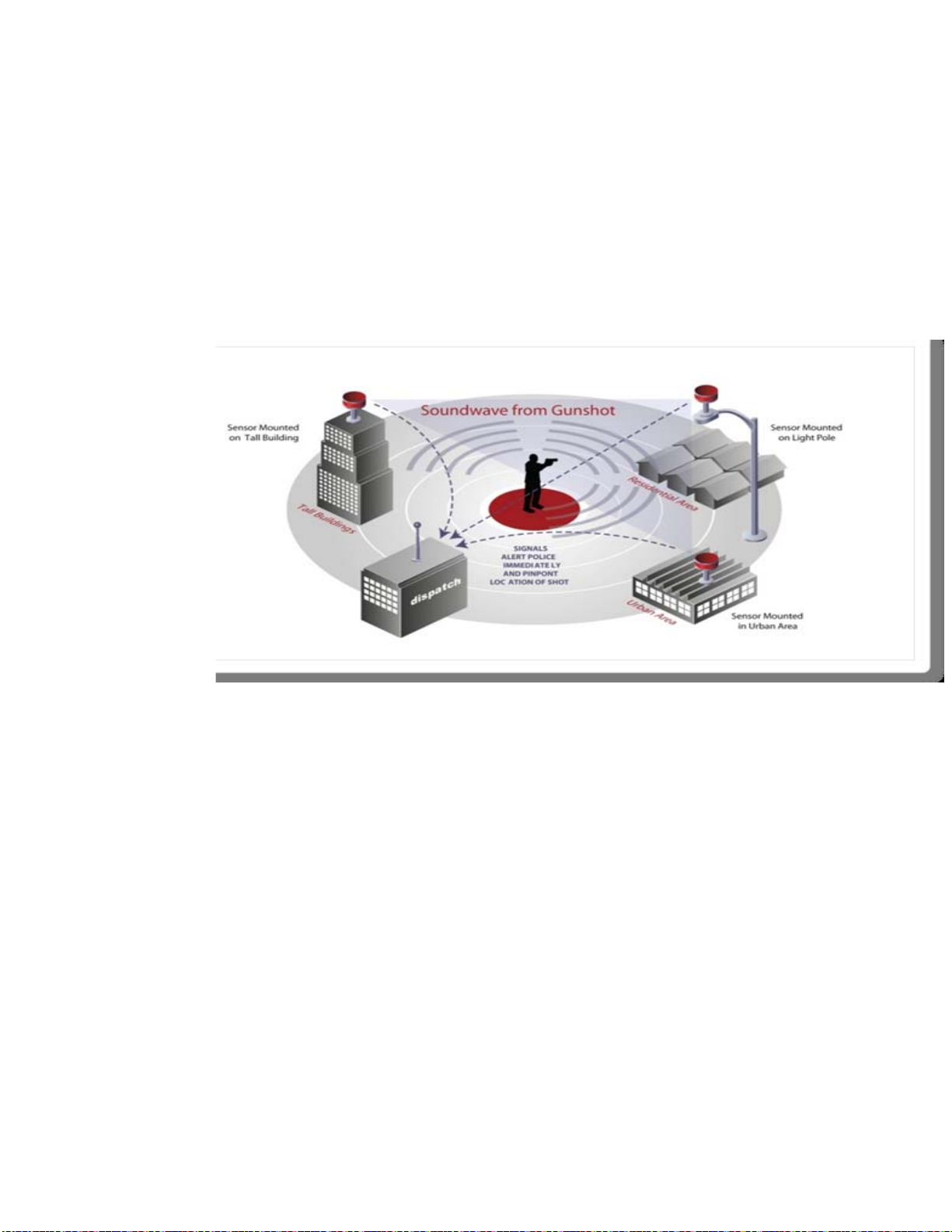
How Does the ShotSpotter GLS Work?
ShotSpotter GLS detects gunfire using specialized acoustic sensors installed in elevated
locations throughout the coverage area.
The sensors detect loud and impulsive sounds and transmitts them to the ShotSpotter
Location server via IP network connections. The ShotSpotter Location server uses
accoustic triangleation and “Classifier” algorithms that look for the unique acoustic
fingerpints of various sounds and classifies each type of incident accordingly, only
notifying on gunshots and fireworks.
Figure 2. The ShotSpotter GLS Sensors Detecting Gunfire
The results are displayed on the ShotSpotter PSC workstations in the dispatch center
and readily available to to units and personnel in the field. Geo-referenced, time
stamped audio of events as heard by each sensor is available for review and allows
dispatchers, law enforcement officers, and commanders to have invaluable situational
awareness prior to arriving at the scene.
System Performance and Accuracy
The system guaranteed to alert on a minimum of 80% of gunfire events with an accuracy
of 25 meters or better. While it is common to locate events outside the array, caution
should be used in dispatching to these sites, as locations tend to become less accurate.
ShotSpotter will train dispatch personnel to determine which events outside an array
may warrant action.

ShotSpotter Sensor Installation Guide
8
Installing the Wireless Sensor
Overview
This chapter is an Instruction Guide for ShotSpotter Project Managers and a Reference
Guide for Subcontractor Installers who will install and oversee installing the wireless
sensor system. Some elements of this document may be applicable to wired sensor
systems (wired sensors are no longer used), however, the primary intent of this
document is wireless sensor system.
Wireless Sensor Components
The ShotSpotter wireless sensor unit has the following component types, subsystems,
etc:
Table 1. Wireless Sensor Components
Component Type Choices (Depending on System Deployment)
Pole Attachments for approved pole sites, typical pole attachments
include two set pole clamps with threaded rods for attachment and
two brackets for mounting acoustic sensor and radio.
Mounting Hardware
For roof top assembly; Non-pen cinder-block base unit with
stabilizing pole
Audio sensor unit Audio sensors with GPS receiver.
Alvarion Radio (integrated)
Proxim Radio
Motorola Radio
Radio unit
AirLink Raven X Cellular Modem
Power subsystem AC power adapter and up to 200ft, 2 conductor 16 AWG UV and
water-resistant, non-plenum cable, and crimp contacts with
instructions.

ShotSpotter Sensor Installation Guide
9
When installing sensors on roof tops, it is best to locate the sensor such that it is
invisible from the street (but they should be at least one or two feet above any parapet
when mounted on the roof of a building).
Choose sites and mounting locations that are not easily accessible to the public or to
children.
Installing a Wireless Sensor - Background
Installation cannot begin until the site selection has been completed. Site selection and
permissions of the property owners should be completed at least two weeks prior to
scheduling installers to begin sensor installation. It is the Project Manager’s
responsibility to compile a list of sites, Site Excel Document, with all necessary details
required to gain access to property and properly locate the sensor at the site. The list
must provide contact names and phone numbers of persons providing authorization.
It is the responsibility of the installer to contact authorizing persons at each site and
schedule a time to complete installation. It is recommended that up to 2-3 hours be
allowed for each sensor installation. Allow sufficient time to travel from site to site and
set a half to an hour time window for arrival at each site.
Visually Inspection when Receiving New Equipment
from Factory
It is extremely important that all systems delivered form the ShotSpotter factory be
immediately inspected for any shipping damage. All damage claims must be made by
the customer to the trucking company. If you can visually see that the product has been
damaged in transit, make a notation on the Bill of Lading before signing it. It is also
helpful if you can take a photograph of the damage. It is important to make your claim to
the shipper within 24 hours of receipt of the damaged product. Call the ShotSpotter
Project Manager (PM) if there is shipping damage. The PM is responsible for making
sure the claim is filed within 24 hours. Contact the ShotSpotter Shipping Department if
you need further assistance in filing your claim.
If you can visually see that the product has been damaged, REFUSE to accept the
shipment from the carrier. If you discover damage to the product after you have already
accepted and signed for the shipment, contact the Shipping Department at ShotSpotter
Inc immediately. (Important note: DO NOT SHIP THE PRODUCT BACK TO US AT
THIS TIME! Doing so will void any damage claim with carrier.) ShotSpotter Inc will
contact the shipping carrier and arrange to have an inspector come to your premises
and visually inspect the package for damage. If the carrier approves the claim,
ShotSpotter Inc will then send you a replacement product, and the carrier will pick up the
damaged product for return to ShotSpotter Inc.
Inspect the Acoustic Sensor
The acoustic sensor should be free of dents, scratches, or other obvious signs of mis-
handling during shipping. Gently shake the unit to determine if internal hardware may
have come loose in transit. It should not rattle. The unit should be clean and free of

ShotSpotter Sensor Installation Guide
10
debris. The pins of both connectors on the underside should not be bent or pushed in.
Make sure there is a serial number label securely affixed to the unit. The acoustic
sensor package must be a complete assembly with swivel mounting brackets attached.
Inspect the Radio Unit
The radio box (if not integrated) should be clean, sealed, and free of dents, scratches, or
other obvious signs of mis-handling during shipping. Gently shake the unit to determine
if internal hardware may have come loose in transit. It should not rattle. Make sure there
is a serial number label securely affixed to the radio box. This label is usually found on
the back of the unit.
Inspect the Power Subsystem
Make sure the data and power cables do not have any bent pins, none of the pins are
pushed in, no connectors are spread open, the plastic connectors are not cracked or
bent, and the outer sheath is not kinked anywhere.
The radio system kit should be complete with antenna, power cable, RF cable, and
mounting hardware for radio and antenna, where applicable.
Warning: Before installing, it is important to verify the radio system kit to
be installed uses the antenna provided along with the minimum cable lengths provided.
The use of antenna or cables not approved by ShotSpotter, Inc. is expressly forbidden in
accordance to FCC rules CFR47 part 15.204.

ShotSpotter Sensor Installation Guide
11
Equipment List
Bring the following items and equipment to each site when installing a wireless sensor
as listed in the following table:
Table 1. Wireless Sensor Installation Equipment List
Item Description
Sensor components Mounting hardware
Acoustic sensor
Radio Unit
Power Subsystem
Tools Rechargeable drill and power nut driver set
Socket set and ½", ¾" and 7/16” wrenches
Allan wrench set
Needle nose pliers
Electric screw driver and multiple screw drivers/bit set
Flat jeweler’s and Phillips screwdrivers
Wire stripper and snips
Scissors or knife
Flashlight
Bubble level
2-way radios
Multimeter or Electrical Socket Power Check Tool
The HD-48-00 cord crimping tool
Materials Tape: double-sided and electrical
Banding wire
UV-rated cable tie wraps
Silicone sealant
Coax-seal
Miscellaneous screws, nuts, bolts, washers
Spool of low voltage wire PN BELDEN 5300UG U-1000
ShotSpotter will provide a Gel Battery for testing
Bring extra copies of the installation worksheet
Map of the coverage area
Rubber matts (1 per sensor install)
Cinder blocks (4 per sensor install)

ShotSpotter Sensor Installation Guide
12
Pen
Extendable ladder 20 foot (6.1 meter) minimum height at full extension
Before ascending onto any roof, ensure your personal safety. Read the safety guidelines
that are listed in Chapter 2.
Assemble the Wireless Sensor
The on-site installation takes a couple of hours at most and follows these general steps:
1. Assemble the mounting subsystem.
2. Attach the wireless sensor and antenna to the mounting subsystem.
3. Level the acoustic sensor.
4. Install the Radio Unit (if not integrated).
5. Install the AC power subsystem.
6. Verify communication with the base station.
7. Complete sensor documentation.
Step 1. Assemble the Mounting Subsystem
This section details the alternative mounting solutions and assembly instruction for each
solution. The Site Document provided by the Project Manager should provide details on
the desired mounting solution at each site. Mounting options vary:
Installed using various poles that are attached to a building, where incursion is allowed
roof installation with equipment installed on the roof using a non penetrating mount
roof installation with equipment attached to light poles
utility pole installation using appropriate mounting hardware.
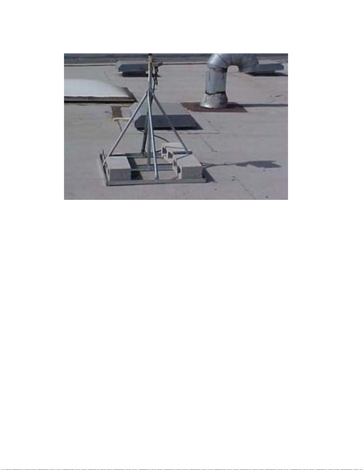
Non-penetrating roof top mounting assembly:
If you are using the non-penetrating assembly make sure you have all the parts and the
correct number of each part (in parantheses) before ascending the roof:
(1) 5-foot Pold (1.5 M)

ShotSpotter Sensor Installation Guide
13
(6) L Brackets
(1) 8-inch Sensor Bracket (20.3 cm)
(4) Stabilizer Brackets
(3) 3-inch Shoulder Bolts (7.6 cm)
(12) ¾ inch Shoulder Bolts (1.9 cm)
(12) Lock Washers
(12) Nuts
(1) Rubber Mat
(4) Cinder Blocks
1. Locate the inventoried hardware on the roof at area specified for sensor install.
2. Assemble square base with cross bars using quantity 8- ¾” inch (22.2 cm)
shoulder bolts, washers and nuts. Be sure to assemble the base with side with two
slots in the “L” brackets flat on the surface.
3. Do not tighten hardware initially.
2 Slots on the Flat

ShotSpotter Sensor Installation Guide
14
4. Assemble the mast using the 4 stabilizer bars, 5 ft. (1.52M) poles and 2 – 3”(5.1-
7.6 CM) shoulder bolts Again do not tighten the hardware. MOUNTING HOLE ON
THE POLE S/B DOWN.
5. Assemble the mast assembly to the square base assembly as shown below.
6. Square up the base assembly and tighten all hardware at this time.
7. Install the 8- ¾” inch (22.2 cm) adapter bracket at the top end of pole to allow for
acoustic sensor swivel mount to fit tightly.

ShotSpotter Sensor Installation Guide
15
8. Place the supplied rubber mat, centered at final location for the assembly and
relocate the assembled mount on the mat.
9. The installers are required to acquire locally up to quantity eight 12 X 8 X 4
cinder blocks to stabilize the mounting assembly. The Cinder blocks must be spread
evenly internal to the base.
ShotSpotter Sensor Installation Guide
16
Once the mounting hardware is assembled, the acoustic sensor, radio and antennas
must be attached to this assembly as shown below.
Step 2. Attach the Sensor and Antenna to the Mounting
Subsystem
The sensor is set on top and the thumb screw tightened. The Antenna is attached
using the supplied antenna mounting hardware brackets.
If the radio unit is not integrated, the radio unit is provided with 2 U-bolts that clamp
around the mast. It is recommended that the radio unit be placed as low as possible
on the mast to lower the center of gravity and avoid tilting.
Detailed sensor and radio mounting instructions are provided in sections 2 and 3
below. Please review these sections prior to completing this task.
There are two versions of the manufactured arm:
•One arm is a straight-through arm
•One arm has a 90 degree bend
This provides for either horizontal or vertical mounting to the light pole. You may
need to mount the radio box on the vertical shaft and the Acoustic sensor on the
horizontal portion of the light pole shaft. Both arms are attached to pole using two
sets of c-clamps that are clasped around the pole using 12-inch (30.5 CM) threaded
rods.

ShotSpotter Sensor Installation Guide
17
.
Step 3. Level the Acoustic Sensor
Attach the swivel mount on top of the stabilizing pole. Adjust the swivel mounts so that
the sensor is placed level to the horizon. The sensor must be placed at a location such
that the scrub foam has a clear view of the sky. There must not be any obstructions
such as overhanging eves, trees, other vegetation, etc.
The swivel mount is designed to allow for freedom of tilt. The Acoustic Chamber must be
level to the horizon. Use a level to ensure accuracy.
Note: The GPS antenna is underneath the scrub foam on top of the unit for maximum
satellite reception. It needs a clear view of the sky.
You may be asked to attach a bird deterrent spike strip to the top.
Step 4. Install the Radio Unit
Warning: Before installing, it is important to verify the radio system kit to
be installed uses the antenna provided along with the minimum cable lengths provided.
The use of antenna or cables not approved by ShotSpotter, Inc. is expressly forbidden in
accordance to FCC rules CFR47 part 15.204.
Each wireless sensor that does not have an integrated radio unit (Alvarion only) will have
one of the following types of Radio Units:
•AirLink Raven X Cellular Modem
•Motorola
•Proxim
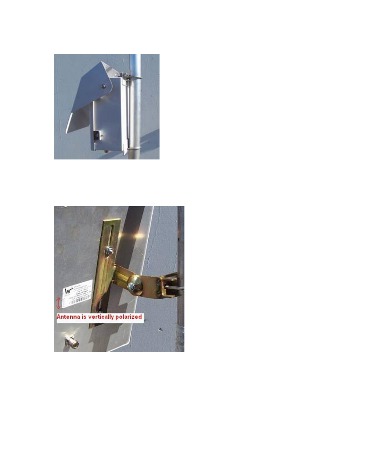
Attach the Radio Unit to the mounting pole, orient the radio unit to point roughly
south (southern exposure), and open the sun shield to a maximum up tilt.
ShotSpotter Sensor Installation Guide
18
Face south and tighten the sunshield in place.
Mount the flat panel antenna and align its face directly towards the base station antenna.
(The base stations should have been installed first on initial installations). Orient the
panel antenna to the vertically polarized position unless instructed otherwise. Do not
point too high above the horizon only 1 degree of up-tilt is needed.
Connect the radio to the sensor and to the antenna using the cables provided. Be gentle
with these connectors they are fragile and over tightening will damage them.
ShotSpotter Sensor Installation Guide
19
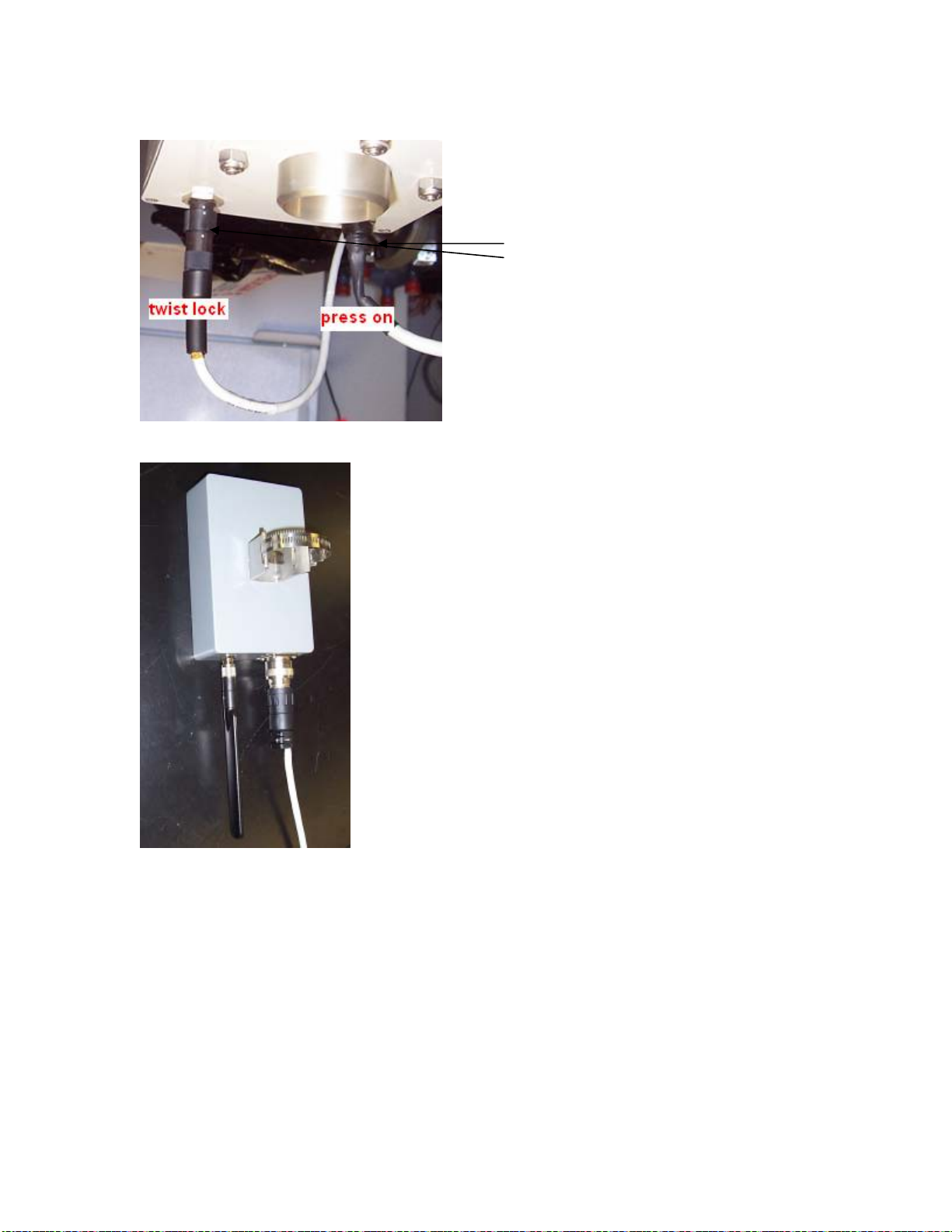
AirLink Raven X Cellular Modem
Attach the Radio Unit to the mounting pole using the hose clamp.
Connect the blade antenna to the radio box. If necessary, bend the antenna until it is
oriented vertically.
Connect the radio to the sensor as outlined above.
Step 5. Install the AC Power Subsystem
This step describes how to install the AC power and perform the following steps:
1. Connect the wall wart power adapter to a standard, 110V outlet.
2. Run the low-voltage power cable from the outlet to the wireless sensor.
3. Cut the power cable to length and crimp the connectors on the end.
4. Connect the wireless sensor to the low-voltage power cable.
Note: These connectors are
provided with some marking
from the manufacturer for
alignment help – some units
have dots, others have a small
arrow indicator, look carefully
for these. Do not use force to
make this inter-connect- you will
damage the connectors!

ShotSpotter Sensor Installation Guide
20
5. Several sources are available for power. Rooftop HVAC units usually have
available outlets, and every outdoor outlet must be enclosed in weatherproof
housings.
6. If an outlet is NOT available on the roof, then find a secure location inside the
building. Remember that the plug must never be removed from the outlet.
Finding an obscure outlet away from public traffic is necessary. Preferred
locations are locked janitor rooms, locked equipment rooms, etc.
7. If no suitable outlet is available, then an electrician will be necessary to provide
the power source. If this is the case, it is up to the general contractor to locate the
wall wart at the proper location with enough low voltage cable to reach the
sensor. Determine the best location then indicate this exact spot on the
Installation Worksheet so that the electrician can find the wall wart, and install the
outlet.
Other items to remember: shown
•The system requires a standard, 110V outlet for power.
•It is important to find an outlet that is not on a switched circuit. You may need to
test the outlet with a Multimeter or a power outlet check tool.
•The low-voltage wire’s maximum length is 200 feet (61M), so try to find an outlet
that is less than 200 feet (61M) from the desired wireless sensor location.
•If non-switched power is not available or if the only outlet is more than 200 feet
(61M) from the desired sensor location, an electrician may be hired to install an
additional outlet. Contact the Project Manager.
•Use non-GFI outlet only.
•Install the lightning platform.
<Picture of DC distribution box and new lightning platform here>
The Deutsch HDT-48-00 crimping tool will initially be provided by ShotSpotter. If you
lose or damage this tool it is your responsibility to repair, replace, or pay for replacement
of the tool it in a timely manner.
Table of contents
Popular Accessories manuals by other brands


Helios
Helios 91739 Installation and operating instructions

Tekscan
Tekscan FlexiForce user manual

ESTEBAN
ESTEBAN LIGHT & BAMBOO EDITION Instructions for use

Digital Control Systems
Digital Control Systems M380 user manual

Ouster
Ouster OS2 Hardware user manual

AGRI TRONIX
AGRI TRONIX Brecknell SBI-521 Series Service manual


