Showline SL Strip 400 RGBW Led Luminaire User manual
Showline Offices
The material in this manual is for information purposes only and is subject to change without notice. Showline
assumes no responsibility for any errors or omissions which may appear in this manual. For comments and
suggestions regarding corrections and/or updates to this manual, please contact your nearest Showline office.
El contenido de este manual es solamente para información y está sujeto a cambios sin previo aviso. Showline no
asume responsabilidad por errores o omisiones que puedan aparecer. Cualquier comentario, sugerencia o corrección
con respecto a este manual, favor de dirijirlo a la oficina de Showline más cercana.
Der Inhalt dieses Handbuches ist nur für Informationszwecke gedacht, Aenderungen sind vorbehalten. Showline
uebernimmt keine Verantwortung für Fehler oder Irrtuemer, die in diesem Handbuch auftreten. Für Bemerkungen
und Verbesserungsvorschlaege oder Vorschlaege in Bezug auf Korrekturen und/oder Aktualisierungen in diesem
Handbuch, moechten wir Sie bitten, Kontakt mit der naechsten Showline-Niederlassung aufzunehmen.
Le matériel décrit dans ce manuel est pour information seulement et est sujet à changements sans préavis. La
compagnie Showline n'assume aucune responsibilité sur toute erreur ou ommission inscrite dans ce manuel. Pour
tous commentaires ou suggestions concernant des corrections et/ou les mises à jour de ce manuel, veuillez s'il vous
plait contacter le bureau de Showline le plus proche.
Note: Information contained in this document may not be duplicated in full or in part by any person without prior written
approval of Showline. Its sole purpose is to provide the user with conceptual information on the equipment mentioned. The use of
this document for all other purposes is specifically prohibited.
Document Number: SL STRIP 400 RGBW LED Luminaires Users
Version as of: 29August 2012
SL STRIP 400 RGBW LED Luminaire Installation & User’s Manual
©2012 Philips Group. All rights reserved.
Dallas
10911 Petal Street
Dallas, TX 75238
Tel: +1 214-647-7880
Fax: +1 214-647-8030
Auckland
19-21 Kawana Street
Northcote, Auckland 0627
New Zealand
Tel: +64 9 481 0100
Fax: +64 9 481 0101
Asia
Unit C, 14/F, Roxy Industrial Centre
No. 41-49 Kwai Cheong Road
Kwai Chung, N.T., Hong Kong
Tel: +852 2796 9786
Fax: +852 2798 6545
Europe
Rondweg zuid 85
Winterswijk 7102 JD
The Netherlands
Tel: +31 (0) 543-542516
www.philips.com/showline

1
SL STRIP 400 RGBW LED Luminaires Installation & User’s Manual
Sh wline
IMPORTANT INFORMATION
Warnings and Notices
Additional Resources for DMX512
For more information on installing DMX512 control systems, the following publication is available for purchase
from the United States Institute for Theatre Technology (USITT), "Recommended Practice for DMX512: A Guide
for Users and Installers, 2nd edition" (ISBN: 9780955703522). USITT Contact Information:
USITT
315 South Crouse Avenue, Suite 200
Syracuse, NY 13210-1844
Phone: 1.800.938.7488 or 1.315.463.6463
www.usitt.org
Showline Limited Two-Year Warranty
Showline offers a two-year limited warranty of its luminaires against defects in materials or workmanship from
the date of delivery. A copy of Showline two-year limited warranty containing specific terms and conditions can
be obtained by contacting your local Showline office.
When using electrical equipment, basic safety precautions should always be followed including the following:
a. READ AND FOLLOW ALL SAFETY INSTRUCTIONS.
b. Do not use outdoors.
c. Do not mount near gas or electric heaters.
d. Equipment should be mounted in locations and at heights where it will not readily be subjected to
tampering by unauthorized personnel.
e. The use of accessory equipment not recommended by the manufacturer may cause an unsafe
condition.
f. Do not use this equipment for other than intended use.
g. Refer service to qualified personnel.
SAVE THESE INSTRUCTIONS.
WARNING: You must have access to a main circuit breaker or other power disconnect device
before installing any wiring. Be sure that power is disconnected by removing fuses or turning the
main circuit breaker off before installation. Installing the device with power on may expose you to
dangerous voltages and damage the device. A qualified electrician must perform this installation.
WARNING: Refer to National Electrical Code® and local codes for cable specifications. Failure to
use proper cable can result in damage to equipment or danger to personnel.
WARNING: This equipment is intended for installation in accordance with the National Electric
Code® and local regulations. It is also intended for installation in indoor applications only. Before
any electrical work is performed, disconnect power at the circuit breaker or remove the fuse to avoid
shock or damage to the control. It is recommended that a qualified electrician perform this
installation.
Installation & User’s Manual SL STRIP 400 RGBW LED Luminaires
2TABLE OF CONTENTS Sh wline
TABLE OF CONTENTS
Showline Offices..................................................................................................................................... Inside Front Cover
IMPORTANT INFORMATION
Warnings and Notices......................................................................................................................................................... 1
Additional Resources for DMX512.................................................................................................................................... 1
Showline Limited Two-Year Warranty .............................................................................................................................. 1
TABLE OF CONTENTS
PREFACE
About this Manual ...................................................................................................................................................................... 3
Included Items............................................................................................................................................................................. 3
SL STRIP 400 RGBW LED Luminaire Accessories ................................................................................................................. 3
SL STRIP 400 RGBW LED LUMINAIRE OVERVIEW
SL STRIP 400 RGBW LED Luminaire Components ................................................................................................................ 4
Major Luminaire Components............................................................................................................................................ 4
LCD Display / Menu System.............................................................................................................................................. 5
INSTALLATION AND SET UP
Power Requirements ................................................................................................................................................................... 6
AC Power Operation........................................................................................................................................................... 6
Connecting Power....................................................................................................................................................................... 6
Connecting SL STRIP 400 RGBW LED Luminaires to AC Power................................................................................... 7
Connecting to the DMX512 Network......................................................................................................................................... 8
Mounting Luminaire ................................................................................................................................................................... 9
OPERATION AND PROGRAMMING
LCD Display and Menu System ............................................................................................................................................... 11
LCD Display and Menu System Operation .............................................................................................................................. 11
Quick Selection Buttons ........................................................................................................................................................... 13
Edit a Preset Button .......................................................................................................................................................... 13
Edit a Chase Button .......................................................................................................................................................... 13
DMX Address Button ....................................................................................................................................................... 13
Dimming Curve Selection ........................................................................................................................................................ 14
Master / Slave Operational Mode ............................................................................................................................................. 15
DMX CONTROL
16-Bit Mode.............................................................................................................................................................................. 16
8-Bit Mode................................................................................................................................................................................ 18
HSIC Mode ............................................................................................................................................................................... 21
SL STRIP 400 RGBW LED Luminaire DMX Timing Channel Detail ................................................................................... 22
SL STRIP 400 RGBW LED Luminaire RDM Parameter IDs ................................................................................................. 27
CLEANING AND CARE
Special Cleaning and Care Instructions .................................................................................................................................... 31
Front Lens Cleaning.................................................................................................................................................................. 31
Service and Maintenance .......................................................................................................................................................... 31
TECHNICAL SPECIFICATIONS
SL STRIP 400 RGBW LED Luminaire Operational Specifications........................................................................................ 32
SL STRIP 400 RGBW LED Luminaire Dimensions ............................................................................................................... 32

About this Manual 3
SL STRIP 400 RGBW LED Luminaires Installation & User’s Manual
Sh wline
PREFACE
1. About this Manual
The document provides installation and operation instructions for the following products:
• SL STRIP 400 RGBW LED Luminaire (IP65 rated)
Please read all instructions before installing or using this product. Retain this manual for future reference. Additional
product information and descriptions may be found on the product specification sheet.
Note: The SL STRIP 400 RGBW LED Luminaire is universal voltage 100 to 240 VAC (auto-ranging).
2. Included Items
Each SL STRIP 400 RGBW LED Luminaire includes the following items:
• SL STRIP 400 RGBW LED Luminaire
• Installation and User’s Manual (this document)
3. SL STRIP 400 RGBW LED Luminaire Accessories
Part Number Description
MC Mega Claw, Black, Anodized
SC Molded Yoke C-Clamp
HC Light Weight Half Coupler
82003 Safety Cable
Installation & User’s Manual SL STRIP 400 RGBW LED Luminaires
4SL STRIP 400 RGBW LED LUMINAIRE OVERVIEW Sh wline
SL STRIP 400 RGBW LED LUMINAIRE OVERVIEW
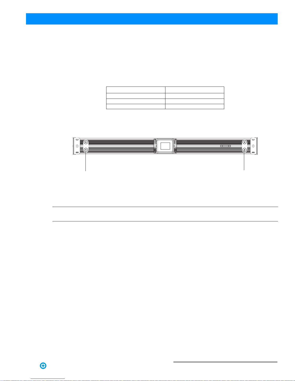
1. SL STRIP 400 RGBW LED Luminaire Components
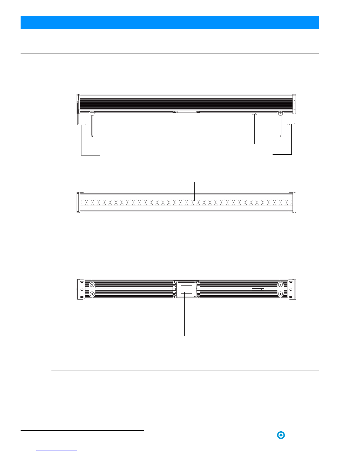
Major Luminaire Components
Figure 1: SL STRIP 400 RGBW LED Luminaire Components
Note: *Mounts can be removed and reversed. See "Mounting Luminaire" on page 9 for more information
Side of Unit
Bottom of Unit
DMX512 /
AC Input
LCD Display / Menu System
Luminaire Mount*
Safety Cable Anchor Point
RDM Input
Top of Unit
DMX512 /
AC Output
RDM Output
Luminaire Mount*
High-Intensity RGBW LED Array (x36)

SL STRIP 400 RGBW LED Luminaire Components 5
SL STRIP 400 RGBW LED Luminaires Installation & User’s Manual
Sh wline
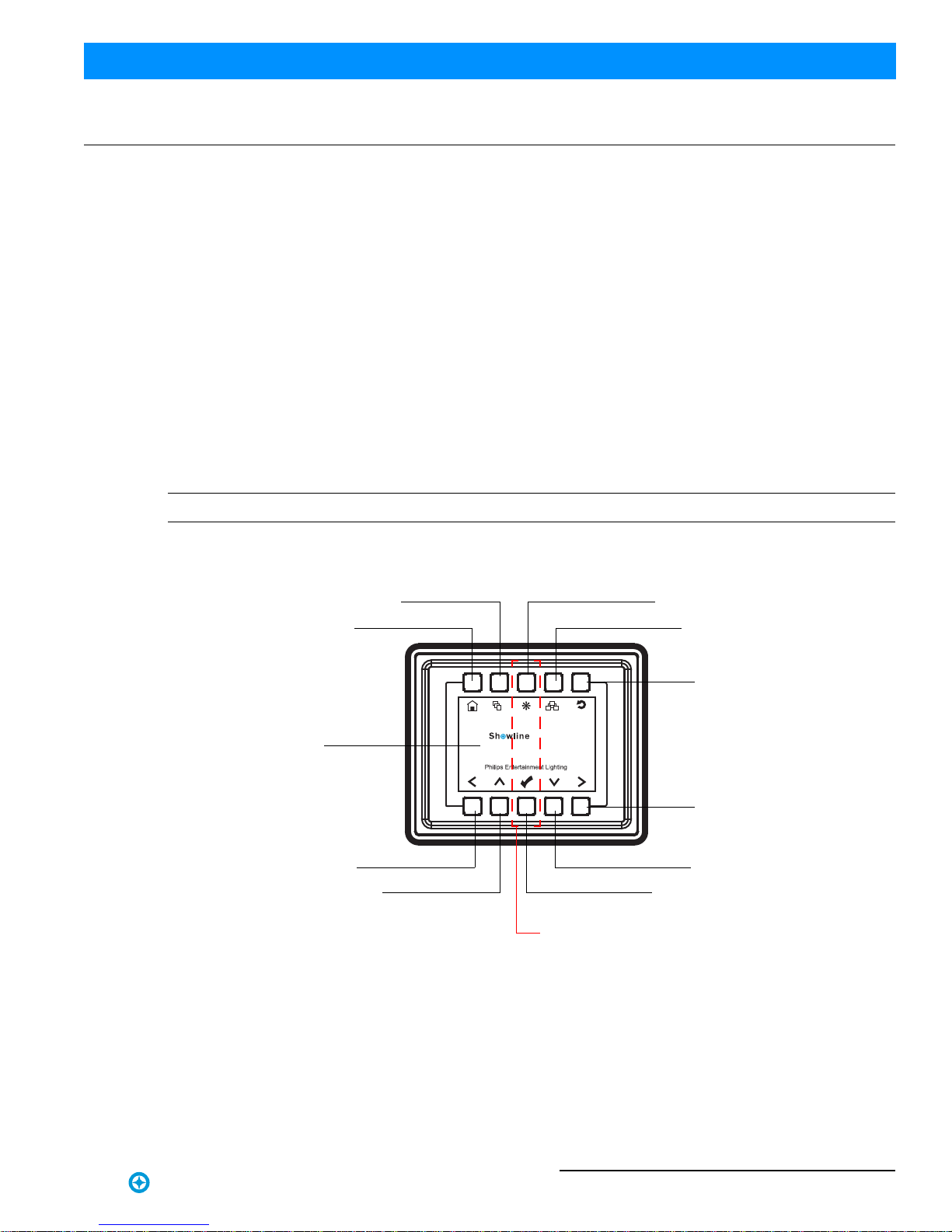
LCD Display / Menu System
Figure 2: LCD Display & Menu System
Note: For Menu operation and programming details, refer to "LCD Display and Menu System" on page 11.
SL STRIP 400
Home (menu settings)
Edit a Preset Edit a Chase
DMX512 Addressing
Return to Main Screen
LEFT Arrow Button
UP Arrow Button CHECK MARK (Accept) Button
DOWN Arrow Button
RIGHT Arrow Button
LCD Display
NOTE: Menu rotates with orientation of luminaire and
menu buttons are always in the same position (with
rotation of menu)
To rotate menu 180 degrees from current orientation,
press and hold the two center buttons for 2 seconds.

Installation & User’s Manual SL STRIP 400 RGBW LED Luminaires
6INSTALLATION AND SET UP Sh wline
INSTALLATION AND SET UP
1. Power Requirements
The SL STRIP 400 RGBW LED Luminaire operates on AC input voltages from 100 to 240 VAC.
WARNING! This unit does not contain an ON/OFF switch. Always disconnect power input cable to completely
remove power from unit when not in use.
AC Power Operation
When connected to an AC source, the unit operates on 100 to 240 volts AC (+/- 10%, auto-ranging). The luminaire
contains an auto-ranging power supply. Each luminaire can draw up to 95 Watts.
WARNING! Maximum amount of units that may be daisy-chained is (A) 17 units 100 ~ 120VAC or (B) 32 units 230
~ 240VAC (10 Amps).
Note: For wiring of AC input connector, refer to "Connecting SL STRIP 400 RGBW LED Luminaires to AC Power"
on page 7.
2. Connecting Power
Units can be powered in one of two ways:
• Direct connection to a AC power source using an AC input cable. For wiring of AC input connector, refer to "Con-
necting SL STRIP 400 RGBW LED Luminaires to AC Power" on page 7.
• Connection from the AC output of another SL STRIP 400 RGBW LED Luminaire. When using this method, it is
very important not to connect any other type of equipment device.
WARNING! Only connect other SL STRIP 400 RGBW LED Luminaires to the AC Output (Thru) connector of a SL
STRIP 400 RGBW LED Luminaire.
Table 1: SL STRIP 400 RGBW LED Luminaire Voltage (VAC) vs. Current*
Voltage (AC) Total Current (A) Voltage (AC) Total Current (A)
100 0.95 180 0.53
110 0.86 190 0.50
120 0.79 200 0.48
130 0.73 210 0.45
140 0.67 220 0.43
150 0.63 230 0.41
160 0.59 240 0.40
170 0.56
Connecting Power 7
SL STRIP 400 RGBW LED Luminaires Installation & User’s Manual
Sh wline
Connecting SL STRIP 400 RGBW LED Luminaires to AC Power
If the unit is supplied with an AC input cable without an input connector installed. The input connector is a user-
supplied accessory.
Table 2 describes how to connect power to your SL STRIP 400 RGBW LED Luminaire. Field wiring of the SL
STRIP 400 RGBW LED Luminaire is straight forward. A total of 3 wires/conductors is supplied from the unit. The
following wiring scheme is used:
Table 2: SL STRIP 400 RGBW LED Luminaire (IP65 Rated Models) AC Input Connections
Figure 3: SL STRIP 400 RGBW LED Luminaire AC Input & Output Connections
CAUTION: In the event the AC input cable of this luminaire is damaged, it must be replaced, by the user, with an
approved cable through an Authorized Showline Dealer or Service Center.
Wire Color Purpose
Brown Main / Line (100 to 240VAC)
Blue Neutral
Green/Yellow Ground (Earth)
Bottom of Unit
AC Input AC Output

Installation & User’s Manual SL STRIP 400 RGBW LED Luminaires
8INSTALLATION AND SET UP Sh wline
3. Connecting to the DMX512 Network
Basic DMX512 installation consists of connecting multiple SL STRIP 400 RGBW LED Luminaires together (up to
32 luminaires) in "daisy-chain" fashion. A cable runs from the control console (or DMX512 control source) to the
DMX connector on the first SL STRIP 400 RGBW LED Luminaire. Another cable runs from the other DMX
connector on the first unit to a DMX connector on the next SL STRIP 400 RGBW LED Luminaire (or DMX512
device to be controlled).
Figure 4: SL STRIP 400 RGBW LED Luminaire DMX512 Input / Output Connections
Note: For more information on DMX512 networking and systems, refer to "Additional Resources for DMX512" on
page 1. For SL STRIP 400 RGBW LED Luminaire DMX Mapping, refer to "DMX CONTROL" on page 16.
Figure 5: SL STRIP 400 RGBW LED Luminaire - DMX512 Connections
Bottom of Unit
DMX512 / RDM Input DMX512 / RDM Output
DMX512
DMX512 (out from first
to second luminaire)
DMX512 (out to the next
luminaire or DMX512
controlled device)
SL STRIP 400 RGBW
DMX512 Connections
Note: Remaining pins on each connector are not used.
DMX512 Signal XLR Pin
Common (Drain) 1
DMX512 - 2
DMX512 + 3
(from console or
control device)
LED Luminaires

Mounting Luminaire 9
SL STRIP 400 RGBW LED Luminaires Installation & User’s Manual
Sh wline
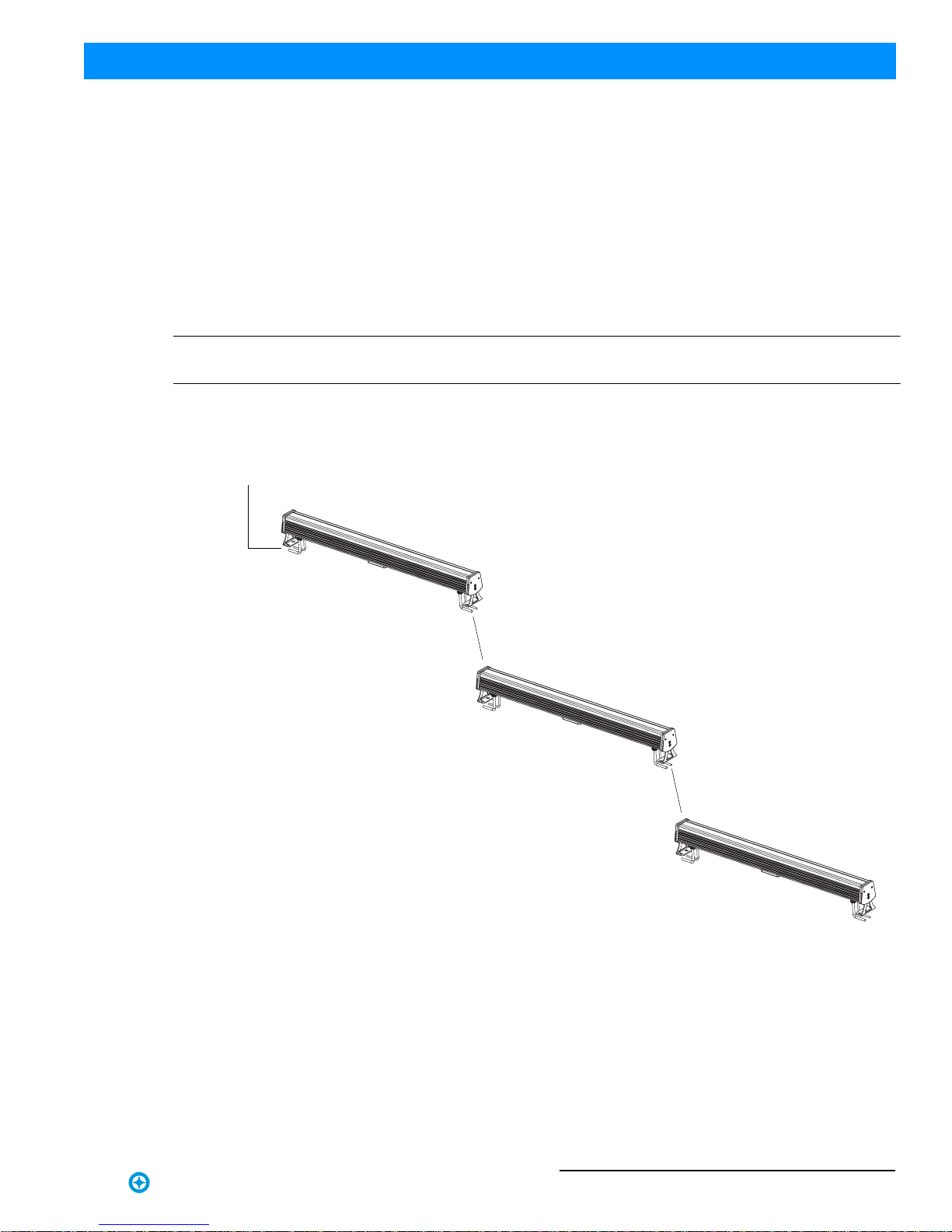
4. Mounting Luminaire
The SL STRIP 400 RGBW LED Luminaire is provided with two mounts and a safety cable anchor point (as
described in "Major Luminaire Components" on page 4).
The two mounts are easily removed and reversed as required (as illustrated in Figure 6). These mounts are designed
to accept a variety of mounting hooks, clamps, etc. for hanging applications or can be set on the mounts for floor
applications. Refer to Figure 7 for additional information.
Figure 6: Mount Removal and Installation
OR
OR
Mount Screws (x2)
Mount
Mount
Mount Screws (x2)
Luminaire

Installation & User’s Manual SL STRIP 400 RGBW LED Luminaires
10 INSTALLATION AND SET UP Sh wline
Simply attach hook, clamp, etc. to the SL STRIP 400 RGBW LED Luminaire mount assembly in the M10 hole.
Note: Mounting hooks, clamps, etc. are sold separately or by others. For available mounting accessories refer to "SL
STRIP 400 RGBW LED Luminaire Accessories" on page 3.
Figure 7: Mounting Luminaire - Hanging Applications
Hooks / Clamps
(sold separately)
Mount
SAFETY CABLE: Is sold separately and recommended
for all hanging installation and may be required by
national and local codes. Use safety cable anchor point
for this fixture.
Mounting hole
size is M10.
Note:
Mount
LCD Display and Menu System 11
SL STRIP 400 RGBW LED Luminaires Installation & User’s Manual
Sh wline
OPERATION AND PROGRAMMING
1. LCD Display and Menu System
The SL STRIP 400 RGBW LED Luminaire’s LCD Display and Menu System provides local control for accessing the
following fixture’s settings:
• Presets (Standard and User Defined)
• Color Filters
• Effects (Chases - preloaded and user defined)
• Strobe / Timing
• Fixture Settings
• Fixture Lockout (to prevent changes)
• Password Setting
• Current Fixture Operational Status
• Setting the DMX512 Address
Note: If there are multiple luminaires in a system, changes would need to be made at each LCD Menu as desired.
Upon power up, the LCD will display the main screen showing the product type/name. If DMX is enabled, the
programmed address will appear after power up.
Figure 8: LCD Display and Menu System
2. LCD Display and Menu System Operation
The LCD Display Menu system consists of several categories. Use the Menu Buttons to access and make changes to
the menu items. When the desired menu item is reached, press the desired Menu Button to display the menu options
and to navigate and configure the menu options as required.
SL STRIP 400
Home (menu settings)
Edit a Preset Edit a Chase
DMX512 Addressing
Return to Main Screen
LEFT Arrow Button
UP Arrow Button OK (Check Mark) Button
DOWN Arrow Button
RIGHT Arrow Button
LCD Display
NOTE: Menu rotates with orientation of Luminaire and
menu buttons are always in the same position (with
rotation of menu)
To rotate menu 180 degrees from current orientation,
press and hold the two center buttons for 2 seconds.


Quick Selection Buttons 13
SL STRIP 400 RGBW LED Luminaires Installation & User’s Manual
Sh wline
3. Quick Selection Buttons
When in Manual Mode, the SL STRIP 400 RGBW LED Luminaire’s features can be accessed via the on-board LCD
menu system or via three quick select buttons:
• Edit a Preset Button
• Edit a Chase Button
• DMX Address Button
Edit a Preset Button
To edit and save a preset:
Step 1. Press Edit a Preset button. Current preset will be shown.
Step 2. Use LEFT and RIGHT arrow buttons to scroll through all presets.
Step 3. Once at desired preset, use UP and DOWN arrows to access
(highlight) preset parameters. Once in desired parameter, use LEFT
and RIGHT arrow buttons to adjust parameter value as desired.
Step 4. Once all values are adjusted as desired, press OK (Check Mark) button.
Step 5. Save preset menu option will appear. Use LEFT and RIGHT arrow buttons to select preset number.
Step 6. If saving preset, press OK (Check Mark) button. Confirm choice.
Step 7. Preset is now saved.
Edit a Chase Button
To edit and save a chase:
Step 1. Press Edit a Chase button. Current chase will be shown.
Step 2. Use LEFT and RIGHT arrow buttons to scroll through all chases
(Built In and User Chases).
Note: For Built In Chases, only the Speed and Fade parameters may be
changed and saved. For User Chases, Chase Number, Total Steps, Speed, and
Fade Parameters may be changed and saved.
Step 3. Once at desired chase, use UP and DOWN arrows to access (highlight) chase parameters. Once in desired
parameter, use LEFT and RIGHT arrow buttons to adjust parameter value as desired.
Step 4. Once all values are adjusted as desired, press OK (Check Mark) button.
Step 5. Save chase menu option will appear. Use LEFT and RIGHT arrow buttons to select chase number.
Step 6. If saving chase, press OK (Check Mark) button. Confirm choice.
Step 7. Chase is now saved.
DMX Address Button
To edit and save a DMX address:
Step 1. Press DMX Address button. Current DMX Address will be shown.
Step 2. Press OK (Check Mark) button to highlight a digit in the DMX
address.
Step 3. Use LEFT and RIGHT arrow buttons to scroll through all digits.
Step 4. Once at desired digit, use UP and DOWN arrows to change
highlighted digit. Once digit is set, use LEFT and RIGHT arrow buttons to set other digits in DMX address.
Step 5. Once all digits are set in DMX address, press OK (Check Mark) button.
Step 6. DMX will display and is saved.
Edit a Preset
H
S
I
C
12%
0%
43%
HSI Mode
Edit a Preset
Built In Chase 8
Total Steps
Speed
Fade
24
8 S
70%
Edit a Chase
Address
267
DMX Address
Installation & User’s Manual SL STRIP 400 RGBW LED Luminaires
14 OPERATION AND PROGRAMMING Sh wline
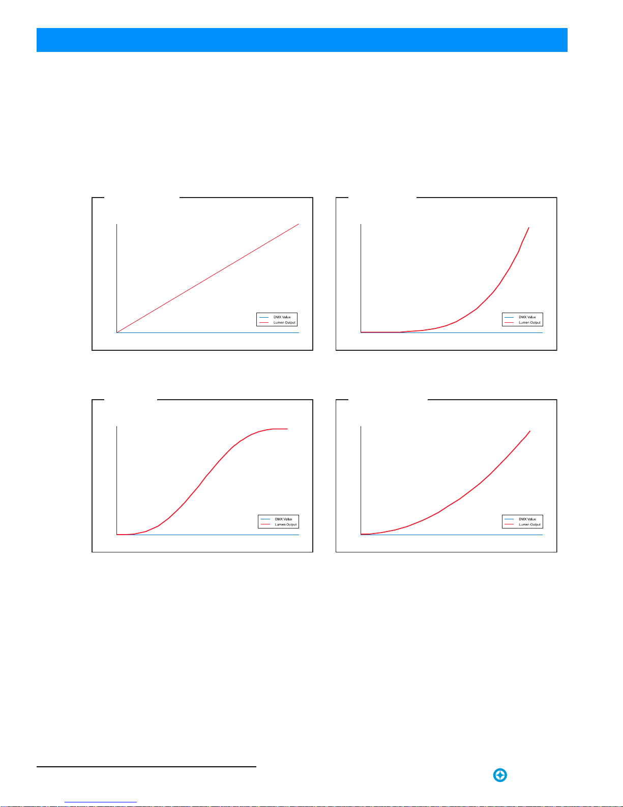
4. Dimming Curve Selection
Through the menu, you are able to select one of four dimming curves:
• Linear Curve
•PL_Curve
• S_Curve
• Square Curve
Figure 10: SL STRIP 400 RGBW LED Luminaire Dimmer Curves
*PL Curve follows the dimming curve of Philips Selecon PL
series LED luminaries.
DMX Value
Lumen Output
0
Linear Curve
DMX Value
Lumen Output
0
S_Curve
DMX Value
Lumen Output
0
Square Curve
DMX Value
Lumen Output
0
PL_Curve *
Master / Slave Operational Mode 15
SL STRIP 400 RGBW LED Luminaires Installation & User’s Manual
Sh wline
5. Master / Slave Operational Mode
The Master / Slave Operational Mode allows one SL STRIP 400 RGBW LED Luminaire to act as the "Master" unit
and all other connected units are controlled by this unit. When a unit is set to "Slave" mode, it will only listen to and
follow any commands sent from a "Master" unit. Only one "Master" unit is allowed in this type of operation.
To setup a master / slave network:
Step 1. Set the first device in the DMX512 chain to Master Mode through the unit’s menu system.
Step 2. Set all other connected units to Slave Mode.
Step 3. The master unit can be controlled via DMX512, RDM or through standalone operation (self-contained
network utilizing on-board effects). The slave units will mimic the master unit’s operation in all cases.
Note: For more information on DMX512 networking and systems, refer to "Additional Resources for DMX512" on
page 1. For SL STRIP 400 RGBW LED Luminaire DMX Mapping, refer to "DMX CONTROL" on page 16.
Figure 11: SL STRIP 400 RGBW LED Luminaire - Master / Slave Configuration
DMX512 (out from first
to second luminaire)
DMX512 (out from
second to next luminaire)
DMX512 (in - from a
DMX controller)
Optional:
SL STRIP 400 RGBW
LED Luminaires
Master Unit
Slave Unit
Slave Unit
Installation & User’s Manual SL STRIP 400 RGBW LED Luminaires
16 DMX CONTROL Sh wline
DMX CONTROL
This section contains information for operating the luminaire using DMX control in 16-bit, 8-Bit, or HSIC (Hue,
Saturation, Intensity and Color Correction) modes. For Menu options and detailed information, see "LCD Display
and Menu System" on page 11.
Note: These tables assume a DMX start address of 1. When a different starting address is used, this address becomes
channel 1 function and other functions follow in sequence.
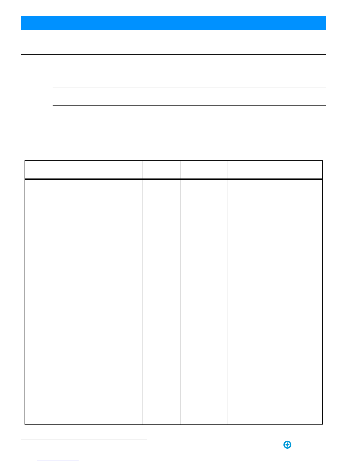
1. 16-Bit Mode
Table 3 provides DMX channel mapping of all DMX512 control values when the SL STRIP 400 RGBW LED
Luminaire is in 16-bit DMX512 mode (as set by the luminaire’s menu system).
Table 3: SL STRIP 400 RGBW LED Luminaire DMX Channel Mapping (16-Bit Mode)
DMX
Channel Parameter Range DMX Range% Default - recom-
mended console
default values Description
1 Master Intensity - High 0 - 65535 0 - 100% 0 16-bit control for Intensity of LED settings.
2 Master Intensity - Low
3 Red - High Byte 0 - 65535 0 - 100% 0 16-bit control for of Red LEDs 0 to full.
4 Red - Low Byte
5 Green - High Byte 0 - 65535 0 - 100% 0 16-bit control for of Green LEDs 0 to full.
6 Green - Low Byte
7 Blue - High Byte 0 - 65535 0 - 100% 0 16-bit control for of Blue LEDs 0 to full.
8 Blue - Low Byte
9 White - High Byte 0 - 65535 0 - 100% 0 16-bit control for of White LEDs 0 to full.
10 White - Low Byte
11 Color Presets 0 - 255 0 - 100% 0
Select presets, variable color filters or
chases as follows:
Channel OFF (disabled) DMX 0 - 4
Preset 0 (OFF) DMX 5 - 6
Preset 1 DMX 7 - 8
Preset 2 DMX 9 - 10
Preset 3 DMX 11 - 12
Preset 4 DMX 13 - 14
Preset 5 DMX 15 - 16
Preset 6 DMX 17 - 18
Preset 7 DMX 19 - 20
Preset 8 DMX 21 - 22
Preset 9 DMX 23 - 24
Preset 10 DMX 25 - 26
Preset 11 DMX 27 - 28
Preset 12 DMX 29 - 30
Preset 13 DMX 31 - 32
Preset 14 DMX 33 - 34
Preset 15 DMX 35 - 36
Preset 16 DMX 37 - 38
Preset 17 DMX 39 - 40
Preset 18 DMX 41 - 42
Preset 19 DMX 43 - 44
Preset 20 DMX 45 - 46
Preset 21 DMX 47 - 48
Preset 22 DMX 49 - 50
Preset 23 DMX 51 - 52
Preset 24 DMX 53 - 54
Preset 25 DMX 55 - 56
Preset 26 DMX 57 - 58
Preset 27 DMX 59 - 60
Preset 28 DMX 61 - 62
Preset 29 DMX 63 - 64
Preset 30 DMX 65 - 66
Preset 31 DMX 67 - 68
CF_0_Color OFF DMX 69 - 70
16-Bit Mode 17
SL STRIP 400 RGBW LED Luminaires Installation & User’s Manual
Sh wline
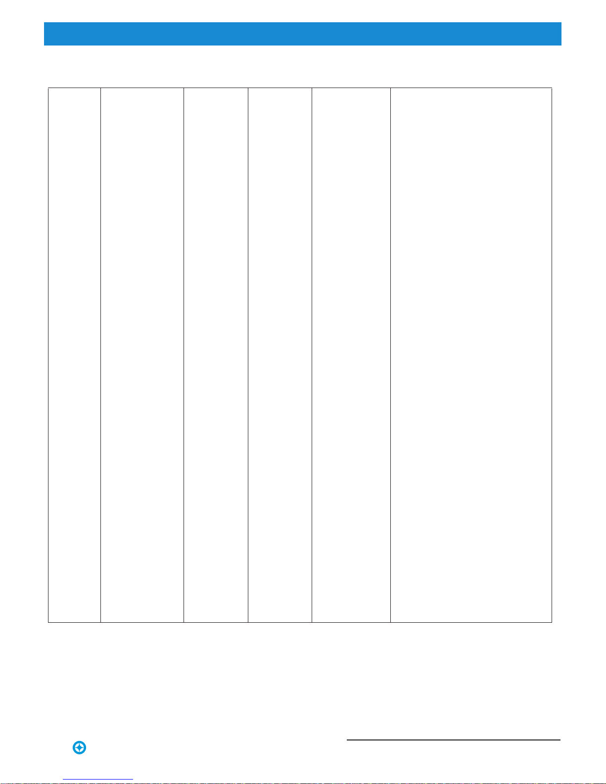
11 Color Presets 0 - 255 0 - 100% 0
Select presets, variable color filters or
chases as follows:
Table 3: SL STRIP 400 RGBW LED Luminaire DMX Channel Mapping (16-Bit Mode)
DMX155 - 156
CF_43_Purple
CF_42_Flame DMX153 - 154Red
DMX151 - 152CF_41_Magenta
DMX149 - 150CF_40_Orange
DMX147 - 148CF_39_Chrome Orange
DMX145 - 146CF_38_Deep Amber
DMX143 - 144CF_37_Yellow
DMX141 - 142CF_36_Spring Yellow
DMX139 - 140CF_35_Pale Green
DMX137 - 138CF_34_JAS Green
DMX135 - 136CF_33_Fem Green
DMX133 - 134CF_32_Green
DMX131 - 132CF_31_Moss Green
DMX129 - 130CF_30_Soft Green
DMX127 - 128CF_29_Marine lue B
DMX125 - 126CF_28_Cyan
DMX123 - 124CF_27_Lighter Blue
DMX121 - 122CF_26_Steel Blue
DMX119 - 120CF_25_Fullt C.T Blue
DMX117 - 118CF_24_RegalBlue
DMX115 - 116CF_23_Slate Blue
DMX113 - 114CF_22_Dluble C.T Blue
DMX111 - 112CF_21_Midnight Maya
DMX109 - 110CF_20_Virgin lue B
DMX107 - 108CF_19_Blue
DMX105 - 106CF_18_Congo Blue
DMX103 - 104CF_17_Surprise ink P
DMX101 - 102CF_16_Fuchsia Pink
DMX99 - 100CF_15_Follies Pink
DMX97 - 98CF_14_Bright Rose
DMX95 - 96CF_13_Flesh Pink
DMX93 - 94CF_12_Pink
DMX91 - 92CF_11_Moroccan Pink
Rotate CW Fast to Slow DMX157 - 171
Rotate ACW Slow to Fast DMX172 - 186
Random Color Fast to Slow DMX187 - 201
CF_1_White 10000K DMX71 - 72
CF_2_White 8000K DMX73 - 74
CF_3_White 6500K DMX75 - 76
CF_4_White 5600K DMX77 - 78
CF_5_White 5000K DMX79 - 80
CF_6_White 4500K DMX81 - 82
CF_7_White 4000K DMX83 - 84
CF_8_White 3200K DMX85 - 86
CF_9_White 3000K DMX87 - 88
CF_10_White 2700K DMX89 - 90
Chase1 DMX 202 - 204
Chase2 DMX 205 - 207
Chase3 DMX 208 - 210
Chase4 DMX 211 - 213
Chase5 DMX 214 - 216
Chase6 DMX 217 - 219
Chase7 DMX 220 - 222
Chase8 DMX 223 - 225
Chase9 DMX 226 - 228
Chase10 DMX 229 - 231
User Chase1 DMX 232 - 234
User Chase2 DMX 235 - 237
User Chase3 DMX 238 - 240
User Chase4 DMX 241 - 243
User Chase5 DMX 244 - 246
User Chase6 DMX 247 - 249
User Chase7 DMX 250 - 252
User Chase8 DMX 253 - 255

Installation & User’s Manual SL STRIP 400 RGBW LED Luminaires
18 DMX CONTROL Sh wline
2. 8-Bit Mode
Table 4 provides DMX channel mapping of all DMX512 control values when the SL STRIP 400 RGBW LED
Luminaire is in 8-bit DMX512 mode (as set by the luminaire’s menu system).
12 Strobe 0 - 255 0 - 100% 0
Controls strobe operations as follows:
Open = DMX 0 - 2
Closed = DMX 3 - 5
Slow Rand = DMX 6 - 7
Med Rand = DMX 8 - 10
Fast Rand = DMX 11 - 12
Strobe Range = DMX 13 - 127 (fastest)
Pulse + Slow Rand = DMX 128 - 129
Pulse + Med Rand = DMX 130 - 131
Pulse + Fast Rand = DMX 132 - 133
Pulse + Range = DMX 134 - 191
Pulse - Slow Rand = DMX 192 - 193
Pulse - Med Rand = DMX 194 - 195
Pulse - Fast Rand = DMX 196 - 197
Pulse - Range = DMX 198 - 255
13 Duration 0 - 255 0 - 100% 0
Strobe Duration is 0 - 85
0 = DMX 0
1 = DMX 1 - 3
x = (DMX Value-1)/3+1
85 = DMX 253-255
14 Intensity Timing 0 - 255 0 - 100% 255 Allows for timing control of intensity. Channel
should default to 255 for smoothest actions using
console and/or manual fades.
15 Color Timing 0 - 255 0 - 100% 255 Allows for timing control of colors. Channel
should default to 255 for smoothest actions using
console and/or manual fades.
16 Control 0 - 255 0 - 100% 255
Control Channel functions of the SL Series
products. Set control channel value from 0 then
turn to desired action. Hold value for at least 5
seconds. Set control channel value to 0 without
any scaling.
Default Setting on Console = DMX 0-4
DIM Response_Normal = DMX 5 - 9
DIM Response_Incandescent = DMX 10 - 14
Dimming Curve_Linear = DMX 30 - 34
Dimming Curve_Square = DMX 35- 39
Dimming Curve_S-Curve = DMX 40 - 44
Dimming Curve_PL-Curve = DMX 45 - 49
Calibration_OFF = DMX 70 - 74
Calibration_ON = DMX 75 - 79
Map_RGBW 16-bit Mode = DMX 100 - 104
Map_RGBW 8-bit Mode = DMX 105 - 109
Map_HSIC Mode = DMX 110 - 114
Reserved ( Future use) = DMX 115 - 250
Table 3: SL STRIP 400 RGBW LED Luminaire DMX Channel Mapping (16-Bit Mode)
Table 4: SL STRIP 400 RGBW LED Luminaire DMX Channel Mapping (8-Bit Mode)
DMX
Channel Parameter Range DMX Range% Default - recom-
mended console
default values Description
1 Master Intensity 0 - 255 0 - 100% 0 8-bit control for Intensity of LED settings.
2 Red 0 - 255 0 - 100% 0 8-bit control of Red LEDs.
3 Green 0 - 255 0 - 100% 0 8-bit control of Green LEDs.
4 Blue 0 - 255 0 - 100% 0 8-bit control of Blue LEDs.
5 White 0 - 255 0 - 100% 0 8-bit control of White LEDs.
Other manuals for SL Strip 400 RGBW Led Luminaire
1
Table of contents
Other Showline Lighting Equipment manuals


