Shurco Donovan Quick-Flip II User manual

Quick-Flip II™ - Electric
P/N 1808554 Rev. D

Shur-Co®, LLC Terms & Conditions
SHIPPING. Orders are shipped F.O.B.
from the Shur-Co®, LLC sites listed below. No full freight is
allowed or prepaid shipment accepted unless quoted and approved in writ-
ing prior to acceptance of the order. All shipments are made by the most rea-
sonable means in accordance with size and weight of order, unless specifi ed
routing instructions are furnished by the customer. Shipments are made daily
via U.P.S. and common carrier. Claims for shortages must be made within 10
days. All claims for damages or loss in transit must be made with the carrier.
No collect calls will be accepted. To ensure delivery of orders, we need your full
street address and phone number. When you receive your shipment, examine
it carefully. Be sure all cartons listed on the delivery sheet are accounted for.
Large items may be packaged separately. If a carton is damaged, open it and
inspect the contents before signing for delivery. If merchandise is damaged,
describe damage on the delivery receipt. Failure on your part to document
damaged or missing merchandise on the delivery receipt releases the carrier
of all liability; repair or replacement will be the customer’s responsibility.
WARRANTY. We warrant all new products are free of defects in materials and
workmanship.* This warranty is effective if products are properly installed and
used for the purpose for which they were intended and applies to the original
buyer only. Except as set forth above or in any product-specifi c warranty docu-
mentation, we make no other warranties, express or implied, including but not
limited to warranties of merchantability of fi tness for a particular use.
Returns of a product for warranty must be accompanied by a Return Merchan-
dise Authorization number (RMA#), obtained by by calling Customer Service
at 866-748-7435, and sent, with freight paid by us, to Shur-Co®, LLC, 2309
Shur-Lok St., PO Box 713, Yankton, SD 57078. All products returned without
an RMA# will be refused. When we issue the RMA#, we will also issue a call
tag to have UPS (or other freight company) pick up the product. C.O.D. returns
not accepted. We will pay no storage fees for a warranty product return prior to
pick by us or the freight company. If a warranty product return is scheduled to
be picked up by us, we will pick up the product at our earliest convenience.
If a product returned is found, in our judgement, to be defective in material
or workmanship, our obligation under this warranty is limited to the repair or
replacement of the product, which will be made by us. Repair or replacement
will be at our discretion, with replacements being made using current products
performing in the equivalent function. Labor charges, other than those incurred
at our factory, including, but not limited to, any labor to install a repaired or re-
placement product, are not covered under this warranty. All expenses associ-
ated with delivering defective products to our factory and delivering repaired or
replacement products from our factory to the owner will be paid by us.
If the product returned is found, in our judgement, to be non-warrantable, the
owner will be contacted to authorize repair work, purchase of a replacement
product or return of the product, all of which will be at the owner’s expense.
Payment authorization must be received by us before any non-warrantable
product is repaired, replaced or returned. All expenses associated with deliver-
ing the repaired non-warrantable product, a replacement product or the non-
warrantable product from our factory to the owner will be paid by the owner.
In no event will we be liable for any damages of any kind to person, product or
property, including but not limited to indirect, incidental, special, consequential
or punitive damages, or damages for loss of profi ts or revenue, even if we
have been advised of the possibility of such damages. There are no warran-
ties for used products or products that have been repaired, altered, modifi ed
or subjected to misuse, negligence or accident. We will not repair or replace
products that fail or malfunction due to ordinary wear and tear, except as ex-
pressly noted in a product-specifi c warranty. Use of non-Shur-Co®, LLC parts
in conjuction with Shur-Co®, LLC products will void this product warranty.
*Certain products have specifi c warranties that differ from this warranty, for example motors and elec-
tronics. Product-specifi c warranty documentation is available for these items. In the event of a confl ict
between this warranty and a product-specifi c warranty, the product-specifi c warranty will govern.
RETURN POLICY. All sales fi nal. See WARRANTY above for return details.
OTHER. All prices, product listings, sizes, weights and manufacturing details
are subject to change without notice. No person is authorized to modify the
foregoing conditions of sale whatsoever.
SHUR-CO® of NORTH DAKOTA
1746 4th Ave. NW
West Fargo, ND 58078
Ph 877.868.4488 | Fax 701.277.1283
SHUR-CO® of OHIO
1100 N. Freedom, St. Rt. 88 & 14
Ravenna, OH 44266
Ph 866.356.0242 | Fax 330.297.5599
SHUR-CO® of TEXAS
34505 I-10 West, S. Frontage Rd.
Brookshire, TX 77423
Ph 866.689.0039 | Fax 281.934.3311
SHUR-CO® UK, Ltd.
Unit 41 Rochester Airport Estates
Laker Rd., Rochester, Kent ME1 3QX
Ph +44 (0)1795.473499
Fax +44 (0)871.272.8278
For more info, log on to our website:
www.shurco.com
Corporate HQ and Outlet Store
SHUR-CO® of SOUTH DAKOTA
2309 Shur-Lok St., PO Box 713
Yankton, SD 57078-0713
Ph 800.474.8756 | Fax 605.665.0501
ShurTite™ Service Centers
SHUR-CO® of CANADA
490 Elgin St., Unit #1
Brantford, Ontario N3S 7P8
Ph 800.265.0823 | Fax 519.751.3997
SHUR-CO® of SIOUX FALLS
47184 258th St., Suite B
Sioux Falls, SD 57107
Ph 844.573.9322 | Fax 605.543.5469
SHUR-CO® of ILLINOIS
Ph 866.356.0246 | Fax 217.877.8270
SHUR-CO® of OHIO
Ph 866.356.0242 | Fax 330.297.5599
SHUR-CO® of COLORADO
10220 Brighton Rd., Unit #1
Henderson, CO 80640
Ph 866.355.9173 | Fax 303.289.2298
SHUR-CO® of FLORIDA
3353 SE Gran Park Way
Stuart, FL 34997
Ph 800.327.8287 | Fax 772.287.0431
SHUR-CO® of ILLINOIS
3993 E. Mueller Ave.
Decatur, IL 62526
Ph 866.356.0246 | Fax 217.877.8270
SHUR-CO® of IOWA
3839 Midway Blvd.
Ft. Dodge, IA 50501
Ph 866.356.0245 | Fax 515.576.5578
SHUR-CO® of MICHIGAN
5100 Lakeshore Dr.
Lexington, MI 48450
Ph 800.327.8287 | Fax 772.287.0431
SHUR-CO®, LLC SERVICE AND DISTRIBUTION CENTERS
P/N 1808554 Rev. D
Thank you for buying this tarping system from Shur-Co®. We appreci-
ate your condence in our products. Please read and thoroughly un-
derstand this manual before installing and/or operating this system.
Pay particular attention to important safety and operating instructions,
as well as warnings and cautions. The hazard symbol is used to
alert users to potentially hazardous conditions and is followed by cau-
tion, warning or danger messages.
Failure to READ AND FOLLOW INSTRUCTIONS could result in fail-
ure of your tarping system and/or personal injury. Your trailer require-
ments may, however, call for minor variations to these instructions.
Please inspect your tarping system periodically and repair or replace
worn or damaged parts.
QUESTIONS? CALL OUR FL HELP LINE:
1-800-327-8287
MON-FRI 8 AM-5 PM EASTERN TIME
We at Shur-Co® are concerned with your safety and the safety of all
those operating this system. Therefore, we have provided safety de-
cals at various locations on your tarping system. Keep decals as clean
as possible at all times. Replace any decal that has become worn
or damaged, painted over or otherwise difcult to read. Replacement
decals are available through Shur-Co® dealers.
To prevent rust, paint all exposed metal, such as weld seams and/or
metal exposed by grinding or cutting, with corrosion-resistant paint.
Quick-Flip™ II EL
P/N 1808554 Rev. D
!
Hardware Identication....................................................................... 1
Clearance Requirements.................................................................... 2
Base Assembly Installation................................................................. 2
Housing Assembly Installation............................................................ 3
Spring Box Installation........................................................................ 4
Pivot Arm Installation.......................................................................... 5
Tarp Installation .................................................................................. 6
Electric Hook-Up............................................................................7-10
Spring Box Cover Installation ........................................................... 11
Upper Arm Rest Installation.............................................................. 12
Replacement Parts......................................................................13-16
1. Wrenches - 1/2", 5/16", 9/16", 5/8", 3/4", 7/8"
2. Ratcheting Socket Wrench
3. Sockets - 1/2", 9/16", 3/4"
4. Allen Wrenches - 1/8", 5/32", 3/16"
5. Drill Bits (metal cutting) - 5/16", 3/8", 1/2", 3/16"
6. Center Punch
7. Hammer
8. Tape Measure
9. Flat Head or Phillips Screwdriver
10. Grinder
11. Air or Electric Impact Driver w/9/16" Socket
12. Metal Saw
13. Steel Welder
14. Hex Driver Bit - 5/16"
15. Phillips Driver Bit - #2
• Spray all bearings and drive chain with penetrating oil as needed.
• Brush springs with steel brush weekly to remove dirt and spray with
penetrating oil.
• Tighten any loose bolts.
• Replace damaged/bent parts.
• Replace worn or broken springs.
• Replace/repair worn or damaged tarps.
TOOLS REQUIRED
TABLE OF CONTENTS
MAINTENANCE
RUST PREVENTION
SAFETY
MESSAGE TO OWNERS
1. Always wear safety glasses during installa-
tion and operation.
2. Stay clear of moving parts.
3. Do not operate under low-hung power lines.
Always check for overhead obstructions be-
fore opening or closing.
4. Open and close tarp only at job site.
5. Place safety decals in visible locations. Re-
place worn or damaged decals.
6. No other use of this system is authorized,
except as designed.
SAFETY INSTRUCTIONS

P/N 1808554 Rev. D
Hardware Identication
1
A
B
D
E
F
C
Tarp length: Measure tarp length with slight tension applied. Compare
actual tarp length with length stated on sheet attached to tarp. If actual
tarp length does not match length on sheet, do not proceed. Call your
local dealer or Shur-Co® FL Customer Service at 1-800-327-8287.
TARP INSPECTION
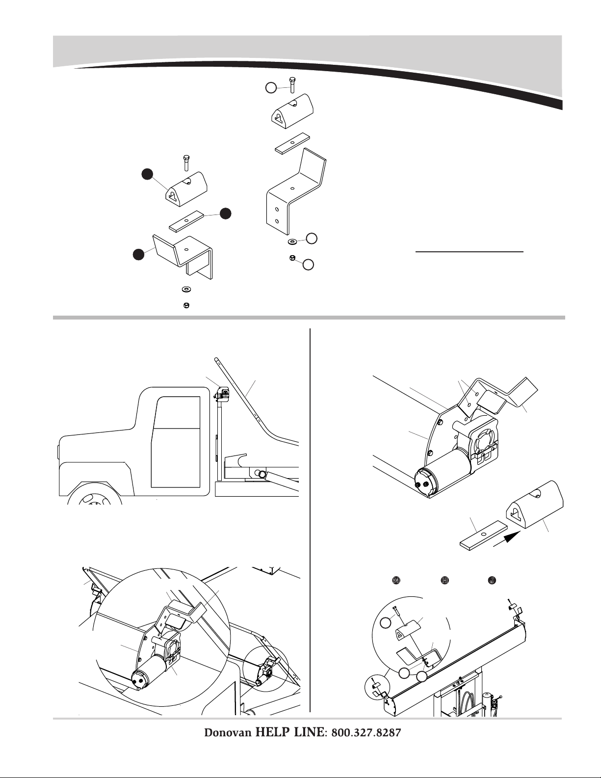
PIVOT ARM REST HARDWARE
Item Part # Description Qty.
M. 1800998
Cap Screw - 5/16" x 1"
2
J. 1800990 Lock Nut - 5/16" 2
H. 1800989 Flat Washer - 5/16" 2
SPRING BOX HARDWARE
Item Part # Description Qty.
D. 1801629 Carriage Bolt -
5/8" x 2 1/2" 8
E. 1801555 Flat Washer - 5/8" 8
F. 1801554 Lock Nut - 5/8" 8
PIVOT ARM HARDWARE
Item Part # Description Qty.
G. 1800561 Pan Hd. Cap Screw -
5/16" x 2 1/4" 20
H. 1800989 Flat Washer - 5/16" 20
J. 1800990 Lock Nut - 5/16" 20
SPRING BOX COVER HARDWARE
Item Part # Description Qty.
K. 1801439 Pan Hd. Cap Screw -
5/16" x 3/4" - SS 4
L. 1800900 Flat Washer -
5/16" - SS 4
HOUSING HARDWARE
Item Part # Description Qty.
A. 1801024 Cap Screw - 1/2" x 4" 1
B. 1800996 Flat Washer - 1/2" 6
C. 1800995 Lock Nut - 1/2" 5
G
H
K
J
M
L
1800996 Flat Washer - 1/2"
1800995 Lock Nut - 1/2"
1801024 Cap Screw - 1/2" x 4"
1801629 Carriage Bolt - 5/8" x 2 1/2"
1801554 Lock Nut - 5/8"
1801555 Flat Washer - 5/8"
1800561 Pan Hd. Cap Screw - 5/16" x 2 1/4"
1800990 Lock Nut - 5/16"
1800989 Flat Washer - 5/16"
1801439 Pan Hd. Cap Screw - 5/16" x 3/4" - SS
1800900 Flat Washer - 5/16" - SS
1800998 Cap Screw - 5/16" x 1"
ELECTRIC/HYDRAULIC HARDWARE
Item Part # Description Qty.
N. 1800790
Cap Screw - 3/8" x 1 1/2"
2
P. 1800991 Lock Washer - 3/8" 2
N
1800790 Cap Screw - 3/8" x 1 1/2"
P
1800991 Lock Washer - 3/8"
ELECTRIC HARDWARE
Item Part # Description Qty.
Q. 1800783 Cap Screw - 1/4" x 1 1/2" 2
R. 1800442 Flat Washer - 1/4" SAE 6
S. 1800699 Lock Nut - 1/4" 2
T. 1800802 Sheet Metal Screw - #10 x 1" 4
U. 1800787 Lock Washer - 5/16" 4
V. 1800431 Hex Nut - 5/16" 4
U
T
S
R
Q
V
1800442 Flat Washer - 1/4"
1800802 Sheet Metal Screw - #10 x 1"
1800783 Cap Screw - 1/4" x 1 1/2"
1800787 Lock Washer - 5/16"
1800699 Lock Nut - 1/4"
1800431 Hex Nut - 5/16"
P/N 1808554 Rev. D
2
There must be at least 6" clearance between components and
tilt frame. If existing exhaust system or hydraulic system compo-
nents are located between tilt frame and cab, adjust component
locations as needed to achieve 6" of clearance.
If existing components interfere with base assembly installation,
and if moving existing components is not practical, fabricate
brackets as needed to prevent interference.
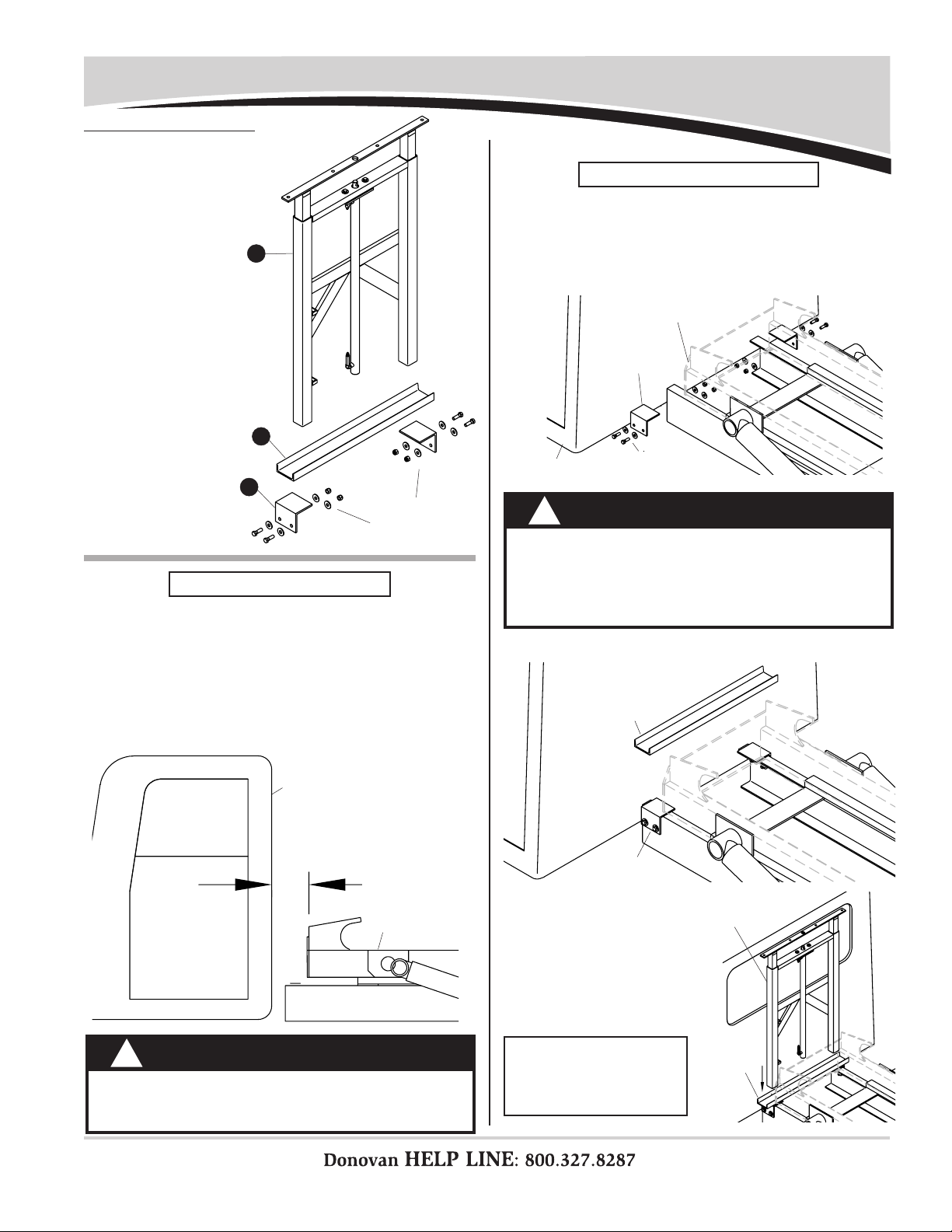
STEP 1: Locate mounting angles on both sides of truck frame,
centering brackets between cab and tilt frame. Align
angles on frame, mark and drill 5/8" holes and fasten
with 5/8" x 2" cap screws, at washers and lock nuts
(supplied by customer) or weld in place (see caution).
Base Assembly Installation
CLEARANCE REQUIREMENTS
BASE ASSEMBLY INSTALLATION
CAUTION
Welding components to truck frame may weaken
frame and will void warranty on truck. Weld angle
brackets to existing brackets on frame when pos-
sible. When not possible, drill holes in frame and bolt
brackets in place.
!
CAUTION
To prevent damage to and ensure proper operation
of Quick Flip II™ system, center base assembly be-
tween cab and hoist with at least 6" of clearance.
!
6" minimum
cab
tilt frame
STEP 2: Align and center mounting channel on mounting
angles and weld in place.
mounting
channel
mounting
angle
Item Part # Description
1. 1801622 Base Assembly
2. 1800726 Mounting Channel
3. 1801966 Mounting Angle
hardware
supplied by
customer
supplied by
customer
tilt frame
cab
mounting
angle
2
1
3
STEP 3: Square and center
base assembly on
mounting channel.
Weld legs to mount-
ing channel.
NOTE: If needed, fabricate
additional bracing to
stabilize base assembly
and mounting channel.
mounting
channel
base assembly
P/N 1808554 Rev. D
3
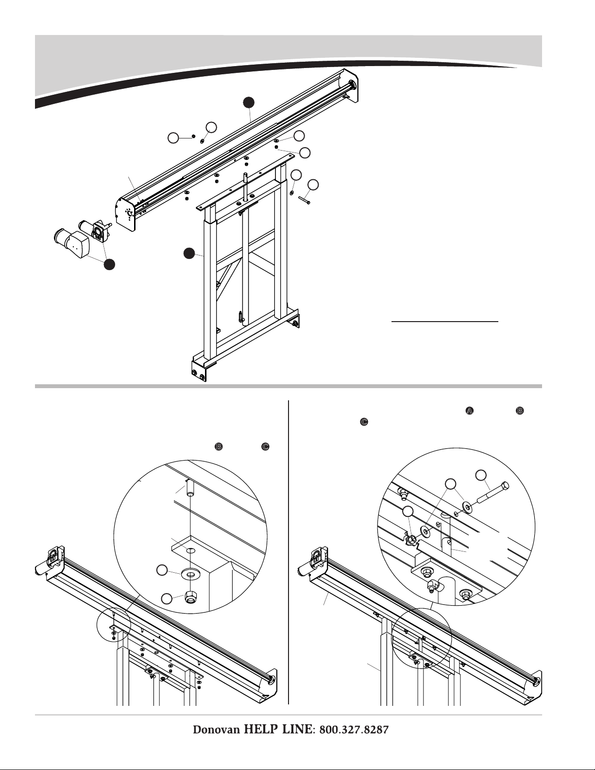
Housing Assembly Installation
STEP 2: Insert studs on housing assembly into holes in base
assembly and fasten with washers B and nuts C.
STEP 3: Fasten hydraulic cylinder rod on base assembly to
housing assembly with screws A, washers B and
nuts C.
Item Part # Description
1. 1800492 Housing Assembly
2. 1801622 Base Assembly
3. 1704878 Durabuilt Motor w/Cover
A. 1801024 Cap Screw - 1/2" x 4"
B. 1800996 Flat Washer - 1/2"
C. 1800995 Lock Nut - 1/2"
hole in base
assembly
stud on
housing
assembly
hydraulic
cylinder
rod
housing
assembly
base assembly
1
2
A
B
B
C
B
C
B
A
C
C
B
3
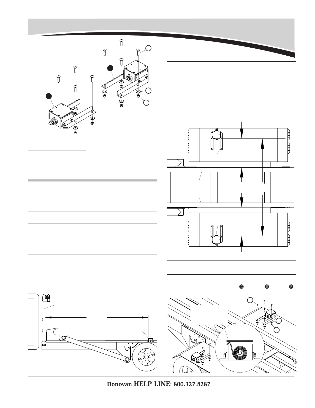
STEP 1: Fasten motor to housing assembly with supplied
fasteners as shown above.
fasteners
supplied
w/motor
P/N 1808554 Rev. D
4
Spring Box Installation
NOTE: Fenders on most stock trucks are not strong enough to
support spring boxes. To support weight and torsion of spring
box, a support frame must be fabricated. In order for system
to operate correctly, fenders must be square and level.
NOTE: Recommended distance needed for spring boxes
to support arms for a 40-yard container is 144" from base
assembly to spring box. To assure containers are covered
and arms do not extend past rear of container, move container
onto truck and center spring boxes between base assembly
and back of container.
STEP 1: Locate spring boxes on truck fenders or on support
frame, with 144" between base assembly and front
of spring boxes.
STEP 2: Space spring boxes 87" apart (see note below). Sys-
tem must be centered on truck, with an equal distance
between truck rails to spring boxes.
IMPORTANT: Locate spring box as low on truck frame as
possible to allow clearance between roll-off container and
spring box. Top of spring box must be less than 5" above
rollers used to support container. If needed, pull container
onto truck and check for clearance.
NOTE: Spring boxes may be welded in place if fenders are
strong enough or customer-fabricated supports are used.
STEP 3:
Fasten spring boxes and backing plates to fenders on
truck with carriage bolts
D
, washers
E
and nuts
F
.
Item Part # Description
1. 1800555 Spring Box Assembly - Driver Side
2. 1800556 Spring Box Assembly - Passenger Side
D. 1801629 Carriage Bolt - 5/8" x 2 1/2"
E. 1801555 Flat Washer - 5/8"
F. 1801554 Lock Nut - 5/8"
1
2
F
D
E
D
E
F
144"
equal
distance
87"
equal
distance
base assembly
spring box
spring box
truck rail
spring box
truck rail
spring catch
must face
front of truck

P/N 1808554 Rev. D
5
STEP 2:
Slide lower arm onto pivot shaft on spring box as-
sembly, positioning bend in arm as shown. Fasten
lower arm to pivot shaft with screws
G
, washers
H
and nuts
J
.
STEP 3: Slide arm coupler into lower arm
and fasten with screws G, washers
H and nuts J.
STEP 4: Slide upper arm onto arm cou-
pler and fasten with screws G,
washers H and nuts J.
NOTES: If holes will not align well enough to insert bolts, run
5/16" drill bit through holes. Place bolt heads on inside of
arms to prevent bolts from catching on container.
STEP 5: Insert cast elbow into
upper arm and fasten
with screws G, washers
H and nuts J.
Pivot Arm Installation
Item Part # Description
1. 1800548 Upper Arm
2. 1800597 90° Cast Elbow
3. 1800547 Arm Coupler
4. 1800545 Lower Arm
5. 1801636 Hex Pivot Arm Shaft
G. 1800561 Pan Hd. Cap Screw - 5/16" x 2 1/4"
H. 1800989 Flat Washer - 5/16"
J. 1800990 Lock Nut - 5/16"
1
2
3
4
1
4
G
H
J
G
H
J
G
H
J
G
HJ
lower arm
pivot
shaft
bend in arm
spring box
H
G
J
H
G
J
H
G
J
arm coupler
lower
arm
cast elbow
upper arm
upper
arm
arm
coupler
5
5
STEP 1: Align
pivot shaft on spring box
as shown and
fasten
with supplied screws and nuts.
pivot arm
spring box
supplied
screws
& nuts

P/N 1808554 Rev. D
6
Tarp Installation
STEP 1: Thread front of tarp with plastic rod into slot in center
of roller bar. Trim ends of rod to t tarp.
STEP 2: Slide rear crosspiece into tarp pocket at rear of tarp.
STEP 3: Center tarp on roller bar and rear crosspiece.
STEP 4: Insert rear crosspiece into 90° elbows. Using holes in
90° elbow as guide, mark and drill 5/16" holes. Fasten
with screws G, washers H and nuts J.
Item Part # Description
1. _______ Tarp
2. 1800546 Rear Crosspiece
G. 1800561 Pan Hd. Cap Screw - 5/16" x 2 1/4"
H. 1800989 Flat Washer - 5/16"
J. 1800990 Lock Nut - 5/16" 1
2
H
G
J
plastic rod on
front of tarp
slot in rollerbar
tarp pocket
rear crosspiece
90° elbow
rear crosspiece
H
G
J
drill
5/16"
holes

P/N 1808554 Rev. D
Item Part # Description
1. 1800090 Hydraulic Pump - 12 Volt - M310
2. 1801623 Pump Mount Bracket
3. 1801223 Spacer - Steel Pump Bracket
4. 1800906 Hose Clamp - 5" to 7"
5. 1801125 Motor Mount Rubber Tire
6. 1801627 Hydraulic Hose - 84 OAL
7. 1800976 Cable Tie - 8"
N. 1800972 Cap Screw - 5/16" x 1 1/2"
P. 1800991 Lock Washer - 3/8"
7
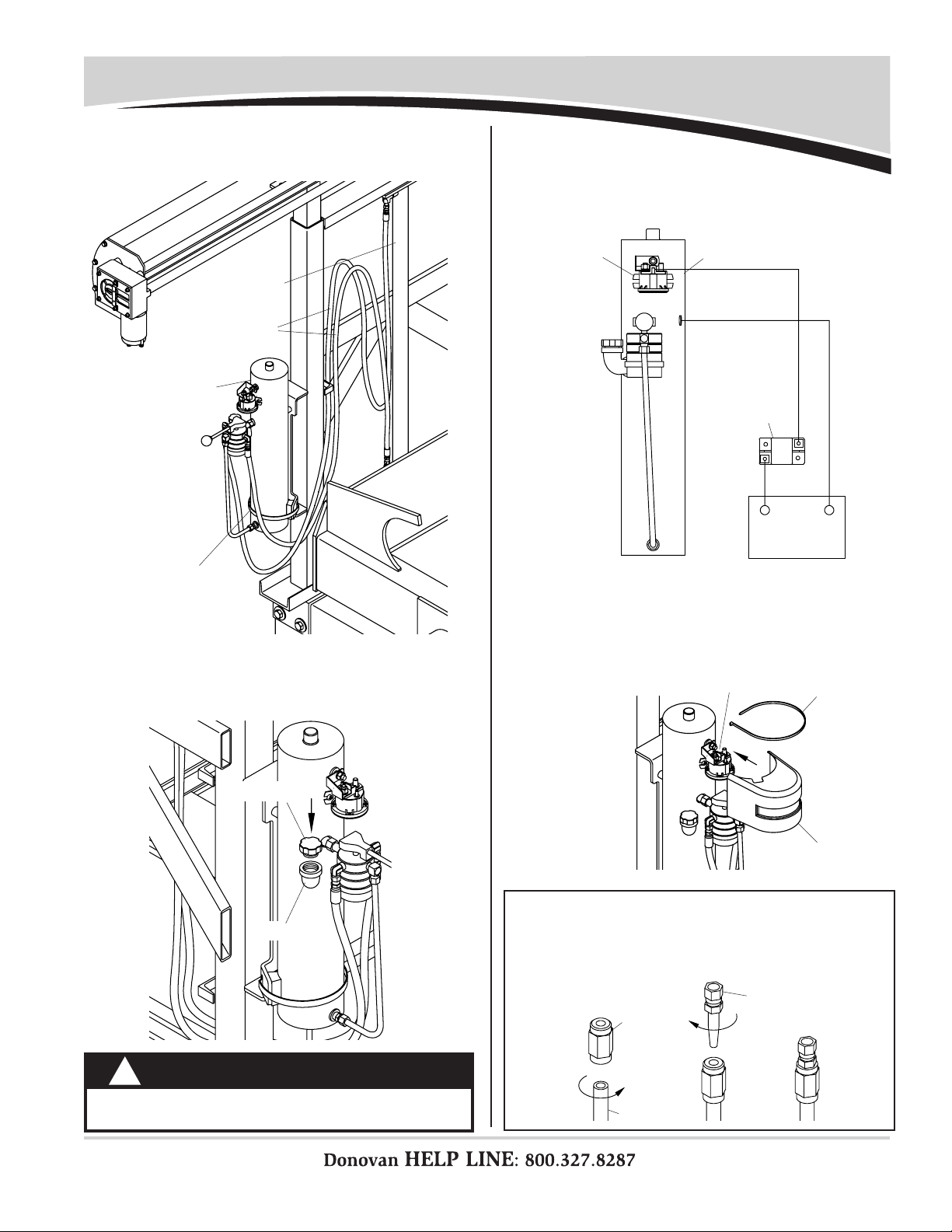
Hydraulic Pump Installation
STEP 1: Locate pump mount bracket on outside of leg or other
easily accessible location. Locate bracket so pump
will be vertical, with control valve and motor on top
and reservoir on bottom as shown.
pump and
mounting
bracket
outside of leg
weld to leg
1
2
3
4
56
N
P
STEP 2: Mark bracket location on trailer. Unfasten and remove
hydraulic pump from bracket. Weld bracket in place,
then replace and refasten pump.
solenoid
manual valve
control
reservoir
hose clamp
bracket
fill port
HYDRAULIC PUMP
solenoid
cover
7
solenoid cover
P/N 1808554 Rev. D
8
Hydraulic Pump Installation - continued
NOTE: To thread tting body onto end of hose, turn body
counterclockwise until body engages hose about 1". Thread
tting insert onto body, turning clockwise until insert is snug
against body. Fitting must be threaded completely onto
hoses to prevent leaking.
hose
reusable
fitting
body
reusable
fitting
insert
STEP 5: Connect negative wire from battery to stud on hydrau-
lic pump.
STEP 6: Connect positive wire from battery to circuit breaker
and from circuit breaker to solenoid on pump.
STEP 7: Place solenoid cover over solenoid. Secure cover to
pump with 8" cable tie.
CAUTION
Replace shipping plug with breather cap on hydrau-
lic pump or pump will be damaged.
!
STEP 3: Connect hoses from hydraulic pump to hydraulic
cylinder, making sure hose clamps are tight around
reservoir.
battery
hydraulic pump
solenoid
reservoir
hydraulic
cylinder
hydraulic
hoses
hose clamp
breather cap
fill port
+_
solenoid
solenoid
cover
cable tie
STEP 4: Remove shipping plug from ll port and ll pump with
approximately 4 quarts Dexron automatic transmis-
sion uid. Install breather cap onto ll port. Do not
reinstall shipping plug.
150a circuit
breaker
p/n1800458

P/N 1808554 Rev. D
9
Electric Installation
Item Part # Description
1. 1800418 Solenoid
2. 1800429 Solenoid Cover
3. 1807726 Toggle Switch
4. 1801265 Toggle Switch Plate
5. 1800302 Ring Terminal - 8 Ga. x 1/4"
6. 1800158 Ring Terminal - 8 Ga. x 3/8"
7. 1800417 Circuit Breaker - 60-Amp 12V
8. 1800441 Butt Connector - 18-22 Ga.
Q. 1800783 Cap Screw - 1/4" x 1 1/2"
R. 1800442 Flat Washer - 1/4" SAE
S. 1800699 Lock Nut - 1/4"
T. 1800802 Sheet Metal Screw - #10 x 1"
U. 1800787 Lock Washer - 5/16"
V. 1800431 Hex Nut - 5/16"
NOTE: New electric motor kits include dual-conductor wire. If
not using new electric kit, use existing wire on truck.
STEP 1: Locate solenoid in sheltered location such as battery
box, cab or under cab. Using solenoid as guide, mark
and drill 1/4" holes. Loosely fasten solenoid with
screws Q, washers R and nuts S.
1
2
7
3
STEP 2:
Locate circuit breaker near battery. Fasten with
screws
T
and washers
R
.
4
5
6
8
solenoid
drill
1/4"
holes
CAUTION
Do not pull dual-strand wires apart. To separate,
cut through insulation between wires carefully with
knife. Pulling wires apart could damage wire insula-
tion and expose wire.This could result in equipment
damage and/or personal injury.
!
NOTE: Cut wires to length and strip only enough wire insulation
to install ring terminals. Insert bare
wire into ring terminals and
crimp securely.
strip wire
insulation
ring terminal crimp securely
CAUTION
Do not spray electric components with pressure
washer or hose.
!
S
T
R
R
Q
U
V
R
T
Q
S
R
T
R
60a
circuit
breaker

P/N 1808554 Rev. D
10
Electric Installation - continued
STEP 5: Divide portion of dual-conductor wire into two single-
strand wires (see caution). Cut section of single-strand
wire to run from positive terminal on battery to circuit
breaker. Crimp 3/8" ring terminal 6 onto one end of
wire and 1/4" ring terminal 5 onto other end. Connect
3/8" ring terminal to positive battery post and connect
1/4" ring terminal to post on circuit breaker marked
BAT.
STEP 8: Run three-strand jacketed toggle switch wire to sole-
noid and cut to length. Connect wire ends to solenoid,
placing ring terminal 5 on post marked BATT+ and
two quick disconnects to tabs marked T1 and T2.
STEP 9: Slide solenoid cover under bolt heads and washers
holding solenoid in place. Tighten fasteners to hold
cover and solenoid in place.
STEP 10: Operate toggle switch to verify tarp is moving in same
direction as shown on toggle. If tarp is not moving in
same direction as toggle, either swap two wires con-
nected to tabs T1 and T2 on solenoid or two wires
connected to motor.
STEP 6: Locate toggle switch
where switch can easily
be accessed by system
operator. Weld toggle
switch plate in place.
STEP 7: Fasten toggle switch to plate with screws T and
washers R.
STEP 4:
Cut section of dual-conductor wire to run from solenoid
to battery. Crimp two 3/8" ring terminals
6
on one end
of wire and connect terminals to posts on solenoid
marked Batt+ and Batt-. Crimp one 1/4" ring terminal
5
and one 3/8" ring terminal
6
on other end of wire.
Connect 1/4" ring terminal to circuit breaker post
marked AUX and connect 3/8" ring terminal to negative
battery post.
STEP 3: Cut section of dual-conductor wire to run from solenoid
to electric motor. Crimp two 3/8" ring terminals 6on
one end of wire and two 1/4" ring terminals 5on
other end. Connect 1/4" ring terminals to motor and
3/8" ring terminals to solenoid.
toggle
switch
plate
toggle
switch
plate
toggle
switch
solenoid
tighten
fasteners
solenoid cover
WIRING DIAGRAM
battery
solenoid
toggle
switch
direct-drive motor
NOTE: Refer to
wiring diagram
for steps 3, 4, 5
and 8. See note
and caution on
previous page.
NOTE: Kit includes three extra butt connectors. If excess
switch wire cannot be coiled, connectors are provided to
shorten switch wires to desired length.
+_
T
R
TEST OPERATION
60a
circuit
breaker

P/N 1808554 Rev. D
11
Spring Box Cover Installation
STEP 1: Fasten spring box covers to spring boxes with screws
K and washers L.
Item Part # Description
1. 1800560 Spring Box Cover
K. 1801439 Pan Hd. Cap Screw - 5/16" x 3/4" - SS
L. 1800900 Flat Washer - 5/16" - SS
1L
K
spring box
spring box cover
K
L
P/N 1808554 Rev. D
12
Pivot Arm Rest Installation
STEP 1: Wind tarp open until arms are completely forward,
stopping just before arms reach housing assembly.
STEP 2:
Position rubber bumpers on pivot arm rests. Align
components on housing assembly brackets, adjusting
so pivot arms rest evenly on rests and do not interfere
with motor. Clamp pivot arm rests in place.
STEP 3: Remove rubber bumpers and weld or bolt pivot arm
rests onto housing brackets (hardware not provided).
STEP 4: Insert bumper hold-
down bars into slots
in rubber bumpers.
Item Part # Description
1. 1801012 Rubber Bumper
2. 1800140 Bumper Hold-Down Bar
3. 1801324 Pivot Arm Rest
M. 1800998 Cap Screw - 5/16" x 1"
H. 1800989 Flat Washer - 5/16"
J. 1800995 Lock Nut - 5/16"
1
2
3
arms
housing assembly
housing
assembly
bracket
pivot
arm
pivot arm rest
rubber bumper
motor
housing
assembly
bracket
pivot arm
rest
weld or bolt
STEP 5: Fasten bumper assemblies to pivot arm rests with
screws M, washers H and nuts J.
bumper
hold-down
bar
rubber
bumper
pivot arm rest
bumper
assembly
M
J
H
M
HJ
P/N 1808554 Rev. D
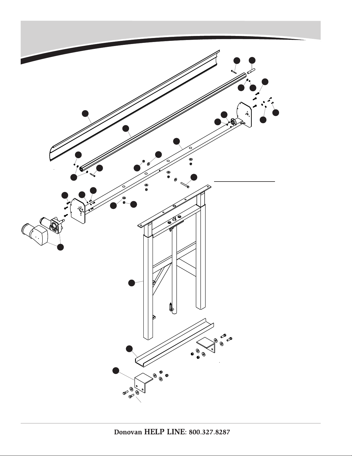
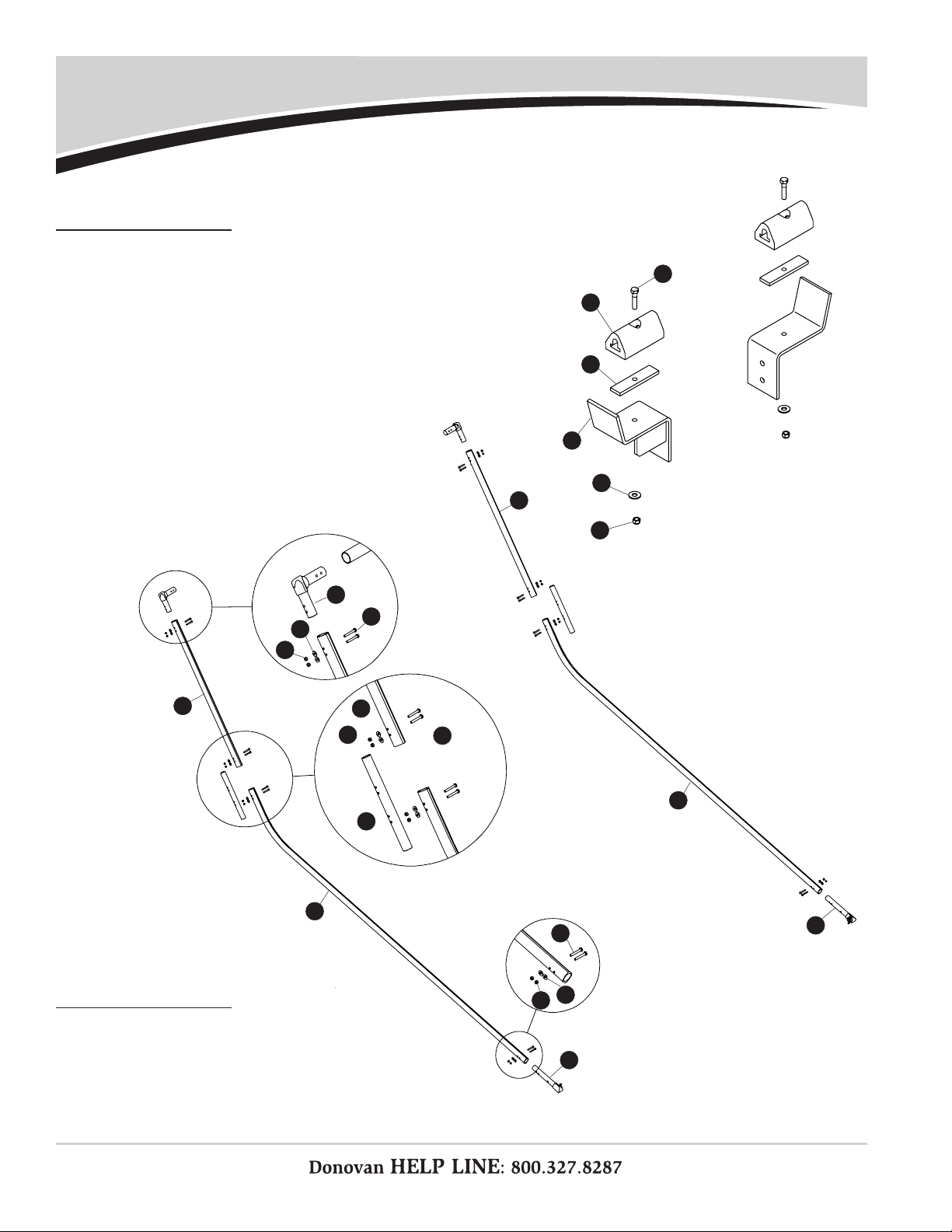
13
Replacement Parts
2
5
8
11
14
1
4
7
9
13
3
6
10
12
15
5
6
12
11
16 17
16
18
18
19
20
21
hardware
supplied by
customer
BASE & HOUSING ASSEMBLIES
Item Part # Description
1800492 Modular Housing Assembly
1. 1800491 Modular Housing Weldment
2. 1801950 Bearing Flange - Reversed
3. 1800699 Lock Nut - 1/4"
4. 1704878 Durabuilt Motor w/Cover
5. 1800460
Self-Tapping Screw - 5/16" x 1 1/4"
6. 1800989 Flat Washer - 5/16"
7. 1800767 Cap Screw - 1/4" x 3/4"
8. 1800784 Flat Washer - 1/4"
9. 1804907 Cap Screw - 5/16" x 3/4"
10. 1800787 Hydraulic Motor Washers
11. 1800996 Flat Washer - 1/2"
12. 1800579 Lock Nut - 1/2"
13. 1801024 Cap Screw - 1/2" x 4"
14. 1800477 Modular Housing Deector
15. 1802015 Roller Bar
16. 1801187 Carriage Bolt - 5/16" x 2 1/2"
17. 1800980 Shaft Extension - 3/4" x 4"
18. 1800990 Lock Nut - 5/16"
19. 1801622 Base Assembly
20. 1800726 Mounting Channel
21. 1801966 Mounting Angle
P/N 1808554 Rev. D
14
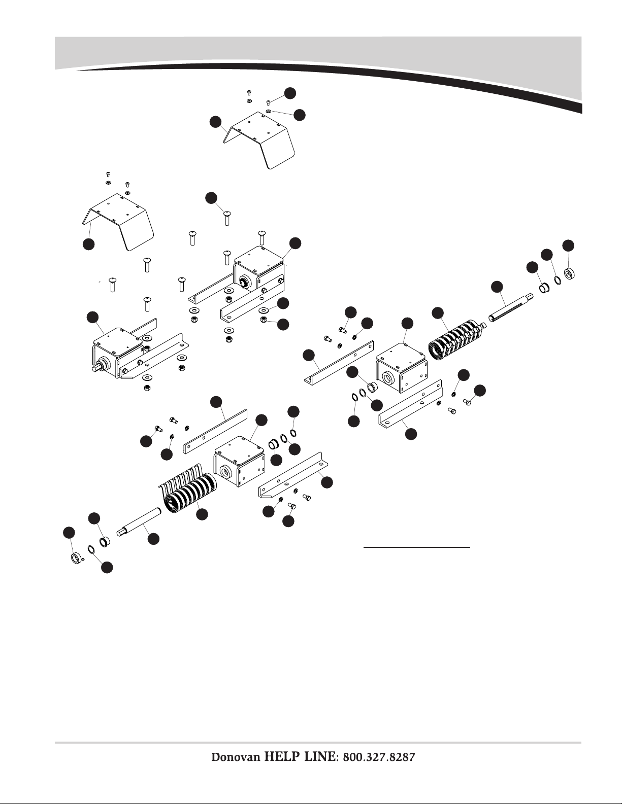
Replacement Parts
SPRING BOXES
Item Part # Description
1. 1800560 Spring Box Cover
2. 1800556 Spring Box Assembly - Pass. Side
3. 1800555 Spring Box Assembly - Driver Side
4. 1801629 Carriage Bolt - 5/8" x 2 1/2"
5. 1801555 Flat Washer - 5/8"
6. 1801554 Lock Nut - 5/8"
7. 1801439 Pan Hd. Cap Screw - 5/16" x 3/4" - SS
8. 1800900 Flat Washer - 5/16" - SS
9. 1801327 Cap Screw - 1/2" x 1"
10. 1800797 Lock Washer - 1/2"
11. 1800551 Mounting Angle #2 of 2
12. 1800763 Torsion Spring
13. 1808514 Spring Shaft - 1 1/4" OD - 7/8" Hex End
14. 1800860 Flanged Bushing - 1 1/4"
15. 1800861 Shaft Collar - 1 1/4"
16. 1800977 Shim - 1 1/4" x .047"
17. 1800542 Spring Box Weldment
18. 1800550 Mounting Angle #1 of 2
19. 1801474 Ring Retainer - 1/4" x .093"
12
7
8
12
11
10
9
17
16
13
15
14
18
19
6
3
5
4
1
18
12
19
16
14
11
10
9
12
13
14
16
15
9
10
14
16
9
10
P/N 1808554 Rev. D
Replacement Parts
15
1
2
3
4
1
4
5
5
6
6
6
7
7
7
8
8
8
PIVOT ARM RESTS
Item Part # Description
1. 1801012 Rubber Bumper - 4" - Drilled
2. 1800140 Bumper Hold-Down Bar
3. 1801324 Pivot Arm Rest
4. 1800998 Cap Screw - 5/16" x 1"
5. 1800989 Flat Washer - 5/16"
6. 1800995 Lock Nut - 5/16"
1
2
3
4
5
6
PIVOT ARMS
Item Part # Description
1. 1800548 Upper Arm
2. 1800597 90° Cast Elbow
3. 1800547 Arm Coupler
4. 1800545 Lower Arm
5. 1801636 Hex Pivot Arm Shaft
6. 1800561 Pan Hd. Cap Screw - 5/16" x 2 1/4"
7. 1800989 Flat Washer - 5/16"
8. 1800990 Lock Nut - 5/16"

P/N 1808554 Rev. D Replacement Parts
16
TARPS
Item Part # Description
1. 1800546 Rear Crosspiece
2. _______ Tarp
3. 1800561 Pan Hd. Cap Screw - 5/16" x 2 1/4"
4. 1800989 Flat Washer - 5/16"
5. 1800990 Lock Nut - 5/16" 1
2
5
3
4
ELECTRIC COMPONENTS
Item Part # Description
1. 1800418 Solenoid
2. 1800429 Solenoid Cover
3. 1807726 Toggle Switch
4. 1801265 Toggle Switch Plate
5. 1800783 Cap Screw - 1/4" x 1 1/2"
6. 1800442 Flat Washer - 1/4" SAE
7. 1800699 Lock Nut - 1/4"
8. 1800802 Sheet Metal Screw - #10 x 1"
9. 1800787 Lock Washer - 5/16"
10. 1800431 Hex Nut - 5/16"
11. 1800302 Ring Terminal - 8 Ga. x 1/4"
12. 1800158 Ring Terminal - 8 Ga. x 3/8"
13. 1800417 Circuit Breaker - 60-Amp 12V
14. 1800441 Butt Connector - 18-22 Ga.
1
2
13
3
8
10
4
5
6
7
11
12
14
8
9
6
6
HYDRAULIC COMPONENTS
Item Part # Description
1. 1800090 Hydraulic Pump - 12 Volt - M310
2. 1801623 Pump Mount Bracket
3. 1801223 Spacer - Steel Pump Bracket
4. 1800906 Hose Clamp - 5" to 7"
5. 1801125 Motor Mount Rubber Tire
6. 1801627 Hydraulic Hose - 84 OAL
7. 1800976 Cable Tie - 8"
8. 1800972 Cap Screw - 5/16" x 1 1/2"
9. 1800991 Lock Washer - 3/8"
1
2
3
4
56
7
solenoid cover
8
9

•
Construction Products
- Arm-Matic™
- DuraPull™
- Econo-Pull™
- Turbo Tarp2™
- 2000 Series
- 5000 Series
- Hammer™
- Bullet™
- Flash™
- Long Arm™
•Waste Products
- SWAT ™
- The Ox™
- Quick-Flip III™
- Sidewinder™
- Sidewinder™ 350
- HyTower™ SL
- HyTower™ DL
- Double-Flip™
- Donovan Belt & Ratchet (DBR)
Table of contents


