Shure Microflex MXWANI8 User manual

© 2015 Shure Incorporated
27A20456 (Rev. 3)
WIRELESS SYSTEM
MICROFLEX
USER GUIDE
WIRELESS
AUDIO NETWORK INTERFACE

IMPORTANT SAFETY INSTRUCTIONS
1. READ these instructions.
2. KEEP these instructions.
3. HEED all warnings.
4. FOLLOW all instructions.
5. DO NOT use this apparatus near water.
6. CLEAN ONLY with dry cloth.
7. DO NOT block any ventilation openings. Allow sufficient distances for adequate ventila-
tion and install in accordance with the manufacturer’s instructions.
8. DO NOT install near any heat sources such as open flames, radiators, heat registers,
stoves, or other apparatus (including amplifiers) that produce heat. Do not place any open
flame sources on the product.
9. DO NOT defeat the safety purpose of the polarized or groundingtype plug. A polarized
plug has two blades with one wider than the other. A grounding type plug has two blades
and a third grounding prong. The wider blade or the third prong are provided for your
safety. If the provided plug does not fit into your outlet, consult an electrician for replace-
ment of the obsolete outlet.
10. PROTECT the power cord from being walked on or pinched, particularly at plugs, conve-
nience receptacles, and the point where they exit from the apparatus.
11. ONLY USE attachments/accessories specified by the manufacturer.
12. USE only with a cart, stand, tripod, bracket, or table specified by the manu-
facturer, or sold with the apparatus. When a cart is used, use caution when
moving the cart/apparatus combination to avoid injury from tip-over.
13. UNPLUG this apparatus during lightning storms or when unused for long
periods of time.
14. REFER all servicing to qualified service personnel. Servicing is required when the ap-
paratus has been damaged in any way, such as power supply cord or plug is damaged,
liquid has been spilled or objects have fallen into the apparatus, the apparatus has been
exposed to rain or moisture, does not operate normally, or has been dropped.
15. DO NOT expose the apparatus to dripping and splashing. DO NOT put objects filled with
liquids, such as vases, on the apparatus.
16. The MAINS plug or an appliance coupler shall remain readily operable.
17. The airborne noise of the Apparatus does not exceed 70dB (A).
18. Apparatus with CLASS I construction shall be connected to a MAINS socket outlet with a
protective earthing connection.
19. To reduce the risk of fire or electric shock, do not expose this apparatus to rain or
moisture.
20. Do not attempt to modify this product. Doing so could result in personal injury and/or
product failure.
21. Operate this product within its specified operating temperature range.
This symbol indicates that dangerous voltage constituting a risk of
electric shock is present within this unit.
This symbol indicates that there are important operating and mainte-
nance instructions in the literature accompanying this unit.
WARNING: This product contains a chemical known to the State of California to cause cancer and birth
defects or other reproductive harm.

3
General Description
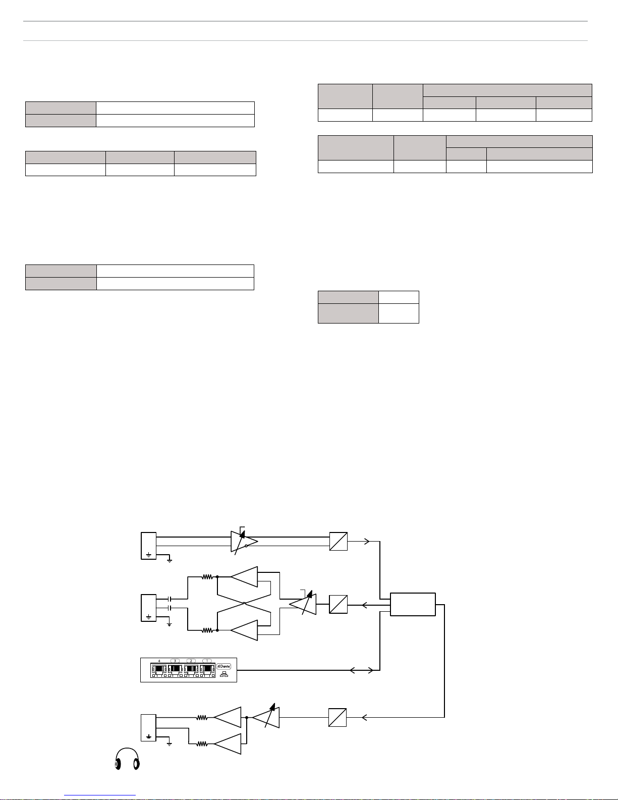
The MXW Audio Network Interface (ANI) is a digital-to-analog breakout box
with a built-in gigabit network switch. It converts digital audio from a network
into analog signals for signal processing or amplification. Input channels add
analog audio to the network and can be routed to MXW microphones as a
translation channel or for personal monitoring.
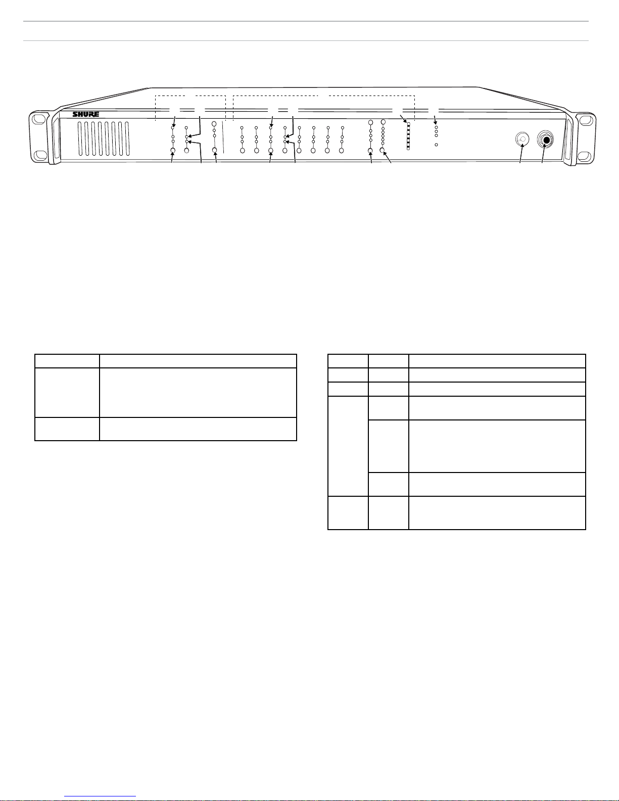
The front panel includes channel status indicators and controls for gain and
mute adjustment. Monitoring features include a headphone jack and dBFS
output meter. A computer can remotely monitor and control a networked unit
from a built-in webserver interface (GUI).
Features
• Converts digital audio from the Dante network into analog output signals
• Built-in gigabit network switch with four ports
• Input channels add analog audio to the digital audio network
• Front-panel gain and mute controls
• Headphone jack for monitoring and troubleshooting
• Monitor LEDs display channel status and output levels
Model Variations
Model Analog Outputs
(mic/line/aux)
Analog Inputs
(line/aux)
Gigabit Ports
MXWANI8 8 2 4
MXWANI4 4 1 4
The ANI is a part of the Microflex Wireless Series (MXW), a complete
solution for meeting room and presentation applications. Developed with
Dantetm technology by Audinate, digital audio is routed over standard IP
equipment across a network of access points, digital-to-analog converters
and computers. Access points mount to a ceiling or wall and communicate
wirelessly with the microphones to add audio to the network. RF
coordination is automatic and continuous, offering worry-free wireless audio
transmission for every event.
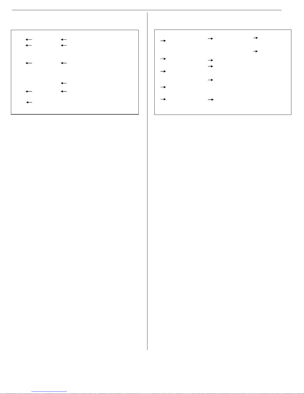
① Power
Connect the power cable from
the ANI to an AC power supply.
Turn on the power switch.
② Audio Outputs
Connect to a signal processor,
amplifier or recording system.
③ Audio Inputs
Connect to a line- or aux-level
analog audio source to add it to
the digital network.
④ Network Port 1 (PoE)
Connect to MXWAPT Access
Point to provide Power over
Ethernet (PoE) and networked
audio and control.
⑤ Network Port 2
Connect to an additional
charger, ANI or computer to
provide networked audio and/or
control.
⑥ Network Port 3
Connect to an additional
charger, ANI or computer to
provide networked audio and/or
control.
⑦ Network Port 4 (Uplink)
Connect to a corporate network
for access to the control
software. (When Port 4 Uplink
mode is enabled, Dante Audio
and Controller data are excluded
from this port.)
MXW Components
① Microflex Microphones
The MXW microphones are available in gooseneck, boundary,
handheld and bodypack models.
② Access Point Transceiver (APT)
Sleek and unobtrusive, the APT mounts to a wall or ceiling to provide
direct, line-of-sight wireless connection to the microphones. The APT
automatically manages the RF spectrum, ensuring consistent, stable
audio transport from the microphones to the digital network.
③ Networked Charging Station (NCS)
The charger recharges microphones without battery removal and
networks battery status for remote monitoring. The charger also
initiates the linking of microphones to an APT, enabling wireless audio
transmission.
④ Audio Network Interface (ANI)
The ANI converts digital audio from the network into analog audio to
send to a signal processor or amplifier.
⑤ Control Software
The control software allows comprehensive remote management of
the MXW system. It operates in a web browser when networked to a
computer.
Microflex Wireless Series
MXW Connections
Requirements: Shielded Cat5e network cable (or higher)
③②
④
⑤⑥
⑦
①
7
8
6
5
1
2
3
4
7
8
6
5
1
2
3
4
lockout
power
ethernet
network audio
push to solo | hold to mute
-9
-18
-24
-36
-48
-60
0
-9
-12
-18
-24
0
aux
mic
adjust
line
sig/clip
mute
INPUT
A
sig/clip
mute
OUTPUT
HEADPHONE
Audio Network Interface
MICROFLEX WIRELESS
B12345678
line
aux
lockout
power
ethernet
network audio
push to solo | hold to mute
-9
-18
-24
-36
-48
-60
0
-9
-12
-18
-24
0
aux
mic
adjust
line
sig/clip
mute
INPUT
A
sig/clip
mute
OUTPUT
HEADPHONE
Audio Network Interface
MICROFLEX WIRELESS
B12345678
line
aux
③
④
①
②
⑤

4
lockout
power
ethernet
network audio
push to solo | hold to mute
-9
-18
-24
-36
-48
-60
0
-9
-12
-18
-24
0
aux
mic
adjust
line
sig/clip
mute
INPUT
A
sig/clip
mute
OUTPUT
HEADPHONE
Audio Network Interface
MICROFLEX WIRELESS
B12345678
line
aux
① Input Channels
Adds analog line- or aux-level signals to the digital network. When the
device is associated to an MXW Group, inputs are automatically routed
to Linked microphone channels (Input A to channels 1-4; Input B to 5-8).
② Output Channels
Converts digital network audio to an analog output for each channel.
When associated to an MXW group, access point channels are
automatically routed to the outputs of the ANI.
③ Channel Selector
Selects a channel to perform the following functions:
Action Function
Single Press • Listen to that channel at the headphone jack
• Display and adjust the channel output level and
attenuation
• Monitor output signal on the level meter
Press and Hold
(3 seconds)
Mute/unmute a channel. Mute is indicated by the
mute LED.
④ Selected Channel LED
Illuminates when a channel is selected.
⑤ Signal Strength LED (sig/clip)
Indicates audio signal strength for each channel:
- Green = Normal
- Amber = Strong
- Red = Clipping (to eliminate clipping, attenuate the signal level at the audio
source)
⑥ Mute LED
Illuminates red when the channel output is muted (hold its channel
select button for 3 seconds). A muted channel is still routed to the
HEADPHONE jack for monitoring or troubleshooting.
⑦ Input Level Selector
Set the selected channel to line- or aux-level to match the input signal.
⑧ Output Level Selector
Set the selected channel to an output level that matches the connecting
device:
- line: +4 dBu
- aux: -10 dBV
- mic: -30 dBV
Front Panel
⑨ Output Attenuation Control
Use the up/down buttons to attenuate the channel output from 0 dB (no
attenuation) to -24 dB in 1 dB increments, and from -24 to -78 in 3 dB
increments.
⑩ Level Meter
Displays a selected channel's audio level in dBFS. It is good practice to
use -18 dBFS on the output meter as an approximation of 0 VU on an
analog meter.
⑪ Hardware Status LEDs
Indicate the status of the hardware:
LED Color Status
Power Green Unit is powered on.
Ethernet Green Connected to an Ethernet device.
Network
Audio
Green All connected receive channels are OK
(receiving digital audio as expected).
Flashing
Green
One or more connected receive channels
experiencing a subscription error or is
unresolved (transmitting device is off,
disconnected, renamed or has incorrect
network setting).
Off No receive channels connected (routing has
not been established).
Lockout Red Front panel gain and mute controls are locked.
The LED will blink when a button is pressed
while the hardware is locked.
⑫ Headphone Volume Knob
Adjusts the volume to the headphone output.
⑬ Headphone Output
1/4" (6.35 mm) output jack for monitoring audio going to and from the
digital audio network.
Note: Audio is present only when the unit is connected to a digital audio
network.
①②
Audio Network Interface (ANI)
④④
⑤ ⑤ ⑩⑪
③
⑥ ⑥⑦ ⑧ ⑨ ⑫⑬
③

5
⑧ Ethernet Link Speed LED (Amber)
- Off = 10/100 Mbps
- On = 1 Gbps (required for digital audio routing)
⑨ Network Interface
Four-port gigabit switch for connecting components together for a single
MXW Group, or for connecting multiple devices to a larger digital audio
network. The following is a description of each port:
Port Description
Port 1
(PoE)
Provides Power over Ethernet (PoE) for the Shure
access point and functions as a standard gigabit port.
Ports 2
and 3
Standard gigabit ports enable the connection of another
MXW network, additional MXWANIs, a MXWNCS
charging stations or an external control system.
Port 4
(Uplink)
• Normal mode (default): this port functions the same as
ports 2 and 3.
• Uplink Mode: only transports control data. This
mode blocks network audio and data for Shure Web
Discovery Application, Dante Controller and Dante
Virtual Soundcard.
Back Panel
① AC Power
IEC connector 100 - 240 V AC.
② Power Switch
Powers the unit on or off.
③ Output Block Connectors (1-8)
Three-pin, low-voltage differential connector provides a line-, aux- or
mic-level analog output for each channel.
④ Chassis Ground (1-8)
Use to directly ground the cable shield to the chassis.
⑤ Input Block Connectors (A,B)
Three-pin, low-voltage differential input connector adds line- or aux-
level analog signals to the digital network.
Note: This input is meant for balanced connection. If an unbalanced source is
used, such as an IPOD or MP3 player, only use pins 1 (signal) and 3 (ground) of
the block connector. See Specifications sections for wiring diagrams.
⑥ Reset Button
Press and hold the button for five seconds to reboot the device with
factory default settings.
⑦ Ethernet Status LED (Green)
- Off = no network link
- On = network link established
- Flashing = network link active
⑤
⑨
③
①②④⑥⑦⑧

6
Control Software for the MXW Audio Network Interface
The MXW Audio Network Interface features a control software to mange
the analog inputs and outputs of the MXW system, in addition to the 4-port
gigabit switch on the back panel of the network interface.
By default, all MXW devices have the password 'admin' applied to the
control software. When logging in for the first time, enter 'admin' into the
field to log on as the administrator. The password can be changed from the
Preferences tab.
Note: For optimal system performance, the control software should not be
open to more than seven tabs or windows.
Operating System Requirements
To operate the control software, the computer must meet the following
requirements:
• Windows: Windows XP, Windows Vista and Windows 7
• Apple: Mac OSX 10.6 and higher (Intel Core 2 Duo processor and later)
• Latest version of Adobe®Flash®Player
Accessing the MXW Control Software
The MXW system uses a device-hosted control software that enables
comprehensive remote control of key setup, monitoring and management
functions. The software is accessible from any PC or Mac on the network, and
opens in a web-browser using Adobe®Flash®.
There are two different control interfaces for the MXW system:
• MXW System control software: Accessed from the Access Point Transceiver
and used for managing the MXW system.
• Audio Network Interface control software: Accessed from the Audio Network
Interface and used for managing that device only.
Follow these steps for accessing MXW control software:
1. Install the Shure Web Device Discovery application.
Download the Shure Web Device Discovery Application from www.
shure.com or from the USB stick supplied with the MXW Access Point
Transceiver. (The required Bonjour device discovery tool is bundled with
the application and will install automatically.)
2. Ensure the computer is on the MXW network.
The computer accesses the control software from an embedded web
server on the device. All networked devices must be connected to the
same network (set to the same subnet).
3. Turn off WiFi
Turn off the PC's WiFi to force the wired network interface.
4. Launch the Shure Web Device Discovery application.
Open the application to view all Shure devices on the network that
feature an embedded server for control software (MXWAPT, MXWANI
and SCM820). Use the Identify button to flash a device's LEDs for easy
identification.
① Tabs
The software has an Inputs/Outputs tab for managing audio and a
Preferences tab for system configurations.
② Identify Button
This button sends a command to the hardware to flash front-panel LEDs
for easy identification.
Control Bar
③ Security Level
Displays the access level of the user: Administrator, Technician, or
Guest.
④ Log Off
Logs the user out of the software.
⑤ Language Selection
Selects the language for the control software interface. This setting will
be saved to the computer.
5. Open the MXW Control Software
Double-click on any Access Point Transceiver to open the MXW
System control software. Double click on an Audio Network Interface
to open that device's software interface. The application can open the
Control Software by IP address or DNS name (selectable from the
Preferences drop-down).
6. Enter Default Password
Enter the default password 'admin' to access the control software.
7. Bookmark the Webpage (recommended)
Bookmark the IP address of the device when it is set to a Static IP
address. Bookmark the device's DNS name when the IP mode is set to
Automatic (DHCP).
⑤
③
②
①
④

7
① Language
Selects the language for the
control software when the
ANI is in Standalone Mode. In
Standalone Network mode, this
is defined in the MXW System
control software.
② Device Serial Number
Displays the devices serial
number.
③ Firmware Version
Displays the current firmware
version of the device.
④ Reset Button
Reboots the device with factory
default settings.
⑤ Register This Product Link
Click to register the device
at www.shure.com to receive
product and software updates.
⑥ Audio Routing Mode
- MXW Mode: Enables automatic
channel routing when the device is a
part of an MXW group (assigned from
the MXW System control software).
- Standalone Mode: Channels must
be routed manually with Dante
Controller software.
⑦ Device Name
Device names can be customized
with up to 31 characters, except
'=','.' or '@'.
⑧ Addressing Mode
Auto: IP settings are Link-Local
or automatically accepted from a
DHCP server.
Manual: IP settings (IP Address,
Subnet Mask, and Gateway) are
static and are entered manually.
⑨ MAC Address
Unique identifier assigned to each
network interface.
⑩ Port 4 Mode
Configures the Port 4 of the
network interface:
- Switched Mode (default): Full
Ethernet support on port 4.
- Uplink Mode: Only control data
is transported. Multicast traffic for
Dante digital audio and the Shure
Web Device Discovery application is
restricted.
⑪ Front Panel Lockout
Disables the front panel controls
on the hardware. Channels can
still be selected for monitoring at
the headphone jack.
⑫ Password
The default password for the
device is 'admin'.
- Admin (default): Full editing rights.
The Admin can enable or disable a
Tech-level logon.
- Tech: Rights are limited to the Inputs/
Outputs page (hardware functions
only).
- Guest: Monitoring only.
① Channel Name
Channel name is customizable by clicking in the text box. Names can
be up to 12 characters long.
② Input Gain Setting (A, B)
Sets the analog input gain level: Line (default) or Aux.
③ Input Audio Meter
Displays input audio levels prior to the analog-to-digital converter.
④ Mute Button
Mutes or unmutes the channel's audio. The button illuminates red
when a channel is muted.
⑤ Output Gain
Sets the output gain level.
⑥ Output Audio Meter
Displays output audio levels prior to the digital-to-analog converter.
⑦ Attenuation
Output attenuation is adjustable in 1 dB increments.
⑧ Notes
Save project notes here, such as installation dates or IP information.
Inputs/Outputs Tab Preferences Tab
③
②
④
① ①
④
⑤
⑥
⑦
③
①
②
④
⑤
⑥
⑩
⑦
⑧
⑨
⑪
⑫
⑧

8
Dantetm Software by Audinate
Audinate software provides additional function and control of the Dantetm digital audio network. Visit Audinate's website for instructions for download and
installation.
Dante Controller
Dante Controller (DC) is a free software by Audinate that is used to
configure and manage a network of Dante devices. Use it to route channels
between Dante-enabled devices and to monitor the status of the device,
clock, and network.
Note: DC software is not required for routing audio within the MXW system.
Use caution when using DC, as changing settings may interfere with MXW
system functionality.
Dante Virtual Soundcard
Dante Virtual Soundcard (DVS) acts as an audio driver used to monitor and
record digital audio without additional equipment. DVS uses a computer's
standard Ethernet ports to transmit and receive up to 64 channels from any
Dante enabled device on the same network.
Shure Firmware Update Manager
Firmware is embedded software in each component that controls functionality. Periodically, new versions of firmware are developed to incorporate additional
features and enhancements. To take advantage of design improvements, new versions of the firmware can be uploaded and installed using the Firmware
Manager tool. Software is available for download from http://www.shure.com.
Perform the following steps to update the firmware:
CAUTION! Ensure the device has a stable network connection during the update. Do not turn off the device until the update is complete.
1. Connect the device and computer to the same network (set to the same subnet).
- To update MXW transmitters, place them in an MXW Networked Charging Station that is connected to the network.
- If the MXW Audio Network Interface is connected via Port 4, ensure that the Network mode is set to Switched mode (default) from the Preferences tab of the ANI control
software.
2. Download Firmware Update Manager and install the application.
3. Open the application.
4. Click Check For Updates button to view new firmware versions available for download.
5. Select the desired firmware and press Downloadto download it to the Firmware Library.
6. From the Update tab, select the new firmware and press Send Updates to begin the firmware update, which overwrites the existing firmware on the device.
Firmware Release Requirements
Microflex Wireless devices comprise a network with multiple communications protocols that work together to ensure proper operation. The recommended
best practice is that all MXW devices are on an identical release. To view the firmware of each MXW device on the network, open the Utility page of the
MXW control software.
The format for Shure device’s firmware is MAJOR.MINOR.PATCH. (Ex. 1.6.2 where 1 is the Major firmware level, 6 is the Minor firmware level, and 2 is the
Patch firmware level.) At minimum, devices that operate on the same subnet should have identical MAJOR and MINOR release numbers.
• Devices of different MAJOR releases are not compatible.
• Differences in the PATCH firmware release level may introduce undesired inconsistencies.

9
Signal Select
and Control
+
-
+
-
-18 dBFS =
+4 dBu
+
-
A
D
+4 dBu =
-18 dBFS
D
A
D
A
Class 0 PoEuplink
Audio Network Interface (ANI)
Audio Frequency Response
20Hzto20kHz(+1,−1.5dB)
Dynamic Range
20 Hz to 20 kHz, A-weighted, typical
Analog-to-Dante 113 dB
Dante-to-Analog 110 dB
Output Noise
20 Hz to 20 kHz, A-Weighted, typical
Line Aux Mic
−84.5dBV −95.2dBV −106.5dBV
THD+N
20 Hz to 20 kHz+4dBu analog input, −10 dBFS digital input
<0.05%
Polarity
Non-inverting, any input to any output
Dimensions
44 mm x 483 mm x 366 mm (1.7 in. x 19.0 in. x 14.4 in.), H x W x D
Weight
MXWANI4 3.1 kg (6.9 lbs)
MXWANI8 3.2 kg (7.1 lbs)
Housing
Steel; Extruded aluminum
Power Requirements
100 to 240 V AC, 50-60 Hz, 1 A
Operating Temperature Range
−18°C(0°F)to63°C(145°F)
Storage Temperature Range
−29°C(-20°F)to74°C(165°F)
Analog Connections
Outputs
Configuration Impedance Clipping Level (minimum)
Line Aux Mic
Active Balanced 310Ω +26.2 dBV +16.2 dBV −3.8dBV
Input(s)
Configuration Impedance Clipping Level (minimum)
Line Aux
Active Balanced 10.6kΩ +23.8 dBV +10.8 dBV
Headphone Output
6.35mm(1/4")TRS,100mW,350Ω,dualmono(willdrivestereophones)
0 dBV=1 V RMS
0 dBu=0.775 V RMS
0 dBV=2.2 dBu
Digital Signal Processing
AD/DA Converter
24-bit, 48 kHz
Latency
Estimated Nominal, ±0.1 ms
Analog-to-Dante 0.21 ms
Dante-to-Analog 0.24 ms
+ TN
TN = Network latency in milliseconds, as set in Dante Controller.
Note: Dante network latency is typically associated with the receiving device.
Networking
Network Interface
Four-Port Gigabit Ethernet Switch, Dante digital audio
Uplink Port (Port 4)
Selectable, blocks multicast traffic
Power over Ethernet (PoE)
Provided on Port 1 to power MXWAPT
Cable Requirements
Cat 5e or higher, shielded, 100 m maximum between network devices
Network Addressing Capability
DHCP, link-local, static
Wiring Diagram
Audio Input
Line
Aux
Audio Output
Line
Aux
Mic
Four-Port Gigabit
Ethernet Switch
Headphone Output

10
Important Product Information
The equipment is intended to be used in professional audio applications.
Note: This device is not intended to be connected directly to a public internet
network.
EMC conformance to Environment E2: Commercial and Light Industrial.
Testing is based on the use of supplied and recommended cable types.
The use of other than shielded (screened) cable types may degrade EMC
performance.
Changes or modifications not expressly approved by Shure Incorporated
could void your authority to operate this equipment.
Industry Canada ICES-003 Compliance Label:
CAN ICES-3 (B)/NMB-3(B)
Authorized under the verification provision of FCC Part 15B.
Please follow your regional recycling scheme for batteries, packaging, and
electronic waste.
Information to the user
This equipment has been tested and found to comply with the limits for a
Class B digital device, pursuant to Part 15 of the FCC Rules. These limits
are designed to provide reasonable protection against harmful interference
in a residential installation. This equipment generates uses and can radiate
radio frequency energy and, if not installed and used in accordance with
the instructions, may cause harmful interference to radio communications.
However, there is no guarantee that interference will not occur in a particular
installation. If this equipment does cause harmful interference to radio or
television reception, which can be determined by turning the equipment off
and on, the user is encouraged to try to correct the interference by one or
more of the following measures:
• Reorient or relocate the receiving antenna.
• Increase the separation between the equipment and the receiver.
• Connect the equipment to an outlet on a circuit different from that to which
the receiver is connected.
• Consult the dealer or an experienced radio/TV technician for help.
1. 經審驗合格之射頻電信終端設備,非經許可,公司、商號或使用者均不得
擅自變更頻率、加大功率或變更原設計之特性及功能。
2. 射頻電信終端設備之使用不得影響飛航安全及干擾合法通信;經發現有干
擾現象時,應立即停用,並改善至無干擾時方得繼續使用。所謂合法通信,
係指依電信法規定作業之無線電信。
3. 輸入、製造射頻電信終端設備之公司、商號或其使用者違反本辦法規定,
擅自使用或變更無線電頻率、電功率者,除依電信法規定處罰外,國家通訊
傳播委員會並得撤銷其審驗合格證明。
4. 減少電磁波影響,請妥適使用
Certifications
Conforms to electrical safety requirements based on IEC 60065.
This product meets the Essential Requirements of all relevant European
directives and is eligible for CE marking.
The CE Declaration of Conformity can be obtained from Shure Incorporated
or any of its European representatives. For contact information please visit
www.shure.com
The CE Declaration of Conformity can be obtained from: www.shure.com/
europe/compliance
Authorized European representative:
Shure Europe GmbH
Headquarters Europe, Middle East & Africa
Department: EMEA Approval
Jakob-Dieffenbacher-Str. 12
75031 Eppingen, Germany
Phone: 49-7262-92 49 0
Fax: 49-7262-92 49 11 4
Email: [email protected]


PT. GOSHEN SWARA INDONESIA
Kompleks Harco Mangga Dua Blok L No. 35 Jakarta Pusat
I.16.GSI31.00501.0211
Europe, Middle East, Africa:
This manual suits for next models
1
Table of contents
Other Shure Accessories manuals

Shure
Shure M95/D SERIES User manual

Shure
Shure N35S Parts list manual

Shure
Shure A412B User manual

Shure
Shure R180 User manual

Shure
Shure UA888 User manual

Shure
Shure 25 Series User manual

Shure
Shure N78s User manual

Shure
Shure V-15 Type III User manual

Shure
Shure ANI22-BLOCK User manual

Shure
Shure MVI User manual

Shure
Shure ANI4IN Series User manual

Shure
Shure N44-7 User manual

Shure
Shure V15 Type IV SUPER TRACK IV User manual

Shure
Shure M71EB User manual

Shure
Shure X100E User manual

Shure
Shure MVI User manual

Shure
Shure X100 User manual

Shure
Shure SEK-2 User manual

Shure
Shure 27EU3222B User manual

Shure
Shure ANI22 User manual