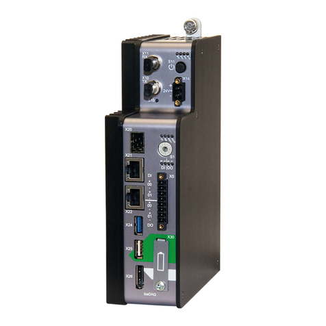
SIAP+MICROS e015a DA15K User manual

e015a DA15K
e015b DA15KE
Data Acquisition Systems
User Guide
SIAP+MICROS S.r.l.
Via del Lavoro,1 tel +39 0438 491411 –fax +39 0438 401573
31020 –Castello Roganzuolo di San Fior (TV) - ITALY email info@siapmicros.com
di San Fior (TV) www.siapmicros.com

e015a DA15K
e015b DA15KE
User guide (v.01) Index Printed in
e015-di DA15K [Eng].docx Siap+Micros S.r.l.
INDEX
1Precautions and safety measures........................................................................................................ 1
1.1 Intended use......................................................................................................................................... 2
1.2 Warnings............................................................................................................................................... 2
1.3 Moving .................................................................................................................................................. 3
1.4 Unpacking............................................................................................................................................. 3
1.5 Safety procedure to turn on DA15K data logger .................................................................................. 3
1.6 During operation................................................................................................................................... 3
1.7 Storage ................................................................................................................................................. 4
1.8 Maintenance ......................................................................................................................................... 4
1.8.1 Device cleaning............................................................................................................................ 4
1.8.2 Protection of power lines.............................................................................................................. 4
1.9 Description of case and connections.................................................................................................... 4
1.9.1 Box of data processing electronics.............................................................................................. 4
1.9.2 Box of data acquisition electronics .............................................................................................. 7
1.10 Configurable 4 –20mA analog input channels..................................................................................... 9
1.11 Description of directories and files........................................................................................................ 9
1.11.1 Drives......................................................................................................................................... 10
1.11.2 Files............................................................................................................................................ 10
2Using DA15K data logger................................................................................................................... 11
2.1 Turning on the DA15K data logger..................................................................................................... 11
2.2 Tabs of data logging software ............................................................................................................ 12
2.2.1 Measure..................................................................................................................................... 12
2.2.2 Parameter .................................................................................................................................. 12
2.2.3 Status......................................................................................................................................... 12
2.2.4 Setting........................................................................................................................................ 13
2.2.5 Log............................................................................................................................................. 13
2.3 Procedure for substitution of data logger software............................................................................. 14
2.4 Acquisition cycle................................................................................................................................. 15
2.5 Storing ................................................................................................................................................ 15
2.6Storing autonomy................................................................................................................................ 15
2.7 Substitution of SD memory card......................................................................................................... 15
3Data Format........................................................................................................................................ 16
4Regulations......................................................................................................................................... 17
4.1 Safety Regulation ............................................................................................................................... 17
4.2 EMC.................................................................................................................................................... 18
5Operating conditions........................................................................................................................... 19
6Quick Guide........................................................................................................................................ 20
6.1 Set clock without DAK ........................................................................................................................ 20
6.2Changing configuration without DAK.................................................................................................. 23

e015x DA15Kx
User guide (v.02) pag.1 Printed in
e015-di DA15K [Eng].docx Siap+Micros S.r.l.
1 Precautions and safety measures
DA15K is a measurement instrument which can acquire, process and storage, electrical quantities; it is made
up of two separate boxes, one dedicated to power supply manager and analog/digital acquisition and the other
dedicated to processing and data logging. This equipment complies with the requirements of the Low Voltage
Directive 73 / 23CEE amended by 93/68 / EEC and the EMC Directive 89/336 / EEC.
The instrument has been designed in accordance with CEI EN 61010; for operator safety, you must follow the
procedures described in this manual and carefully read all the notes preceded by the symbol:
(Pay attention, please refer to documentation)
Or by the symbol:
(Pay attention, risk of electric shock)
DA15K is a device designed in order to be used by educated personnel. Manufacturer declines every
responsibility in case of malfunction due to failure to follow instructions, tampering, uses not described in this
manual, improper use, use by operators not educated. Only authorized personnel should have access to the
work area for normal use and maintenance.
-The device must be connected to an electrical ground (or security) through an AC power cord with three
wires. The cable must be connected to a socket compliant with three contacts rule.
-The instrument must not operate in the presence of flammable gases, fumes or in any environment at risk
of explosion.
-Do not carry out any measure where anomalies are found in the instrument, such as deformation or
breakage.
-Do not work within the apparatus without the presence of a second person in a position to provide a first
aid in case of need.
-Do not remove, replace or modify any electrical or mechanical part without permission.
-Substitution of components and intervention inside should be performed only by qualified and instructed
service personnel, after disconnecting the main power supply.
-Pay attention to any warning label on order to avoid potentially dangerous procedures.

e015x DA15Kx
User guide (v.02) pag.2 Printed in
e015-di DA15K [Eng].docx Siap+Micros S.r.l.
1.1 Intended use
The purpose of this manual is to supply all the information necessary for proper installation and operation of
the product DA15K.
The fields of use of the data logger DA15K are the following:
1) Acquisition and storaging of the meteorological measures.
2) Acquisition and storaging of level (water, snow, etc.).
3) Acquisition and storaging of analogic and digital parameters.
4) Integral system of a remote control for management of aqueducts.
Keep this manual carefully and keep a copy always available for operators.
1.2 Warnings
The manufacturer declines all responsibility in case of failure due to negligence of the instructions, tampering,
uses not described in this manual, improper use, use by operators not educated. Only trained, authorized
personnel should have access to the work area for normal use and maintenance.
Safety Regulation
-The device must be connected to an electrical ground (or security).
-The instrument must not operate in the presence of flammable gases, fumes or in any environment at risk
of explosion.
-Do not remove, replace or modify any electrical or mechanical part without permission.
-Substitution of components and intervention inside should be performed only by qualified and instructed
service personnel, after disconnecting the main power supply.
-Pay attention to any warning label on order to avoid potentially dangerous procedures.

e015x DA15Kx
User guide (v.02) pag.3 Printed in
e015-di DA15K [Eng].docx Siap+Micros S.r.l.
1.3 Moving
In order to avoid any damage to the device during transportation, please keep it in upright position without
shaking.
1.4 Unpacking
Before unpacking and installing the device, please make sure you have taken the following precautions:
- Use proper gloves in order to be protected against possible abrasions etc.
- If you find any damage caused during transport due to the supplier, return the instrument to the supplier.
- Once unpacked, place the DA15K and the parts that make it up on a flat surface.
- Always avoid flip the data logger to protect the display.
- Pay attention to the socket in the front and on the sides of the case of the equipment during operation.
Before installing the device, please check that:
- The network voltage in the installation area complies with the operating conditions of the instrument.
- Check that the main switch on the instrument is turned off.
Avoid turning the power on until you have carefully followed the instructions of installation and start-up in this
manual.
1.5 Safety procedure to turn on DA15K data logger
A safety procedure must be followed when turning on a DA15K with an external power supply and a 12V
backup battery.
1. Connect the battery in the power supply connector at pins BATT –GND (see chapter 1.9 Description
of case and connections).
2. Take care of the polarity of the battery connections: BATT is the positive terminal and GND is the
negative.
3. Connect the external 12V DC power supply in the power supply connector at pins VCC –GND (see
chapter 1.9 Description of case and connections). Take care that the power supply is turned off.
4. Take care of the polarity of the power supply connections: VCC is the positive terminal and GND is
the negative.
5. Turn on the DA15K in battery mode with the external power supply switched off.
6. Turn on the external power supply.
1.6 During operation
During operation, please avoid to alter the electrical connections related to analog and digital inputs; also avoid
to alter the connections of the power supplies.

e015x DA15Kx
User guide (v.02) pag.4 Printed in
e015-di DA15K [Eng].docx Siap+Micros S.r.l.
1.7 Storage
If you plan a long period of inactivity (at least one year), disconnect all cables from the device, put it in a plastic
bag and seal the bag with tape. Affix appropriate indication on the bag's contents and weight of the device by
inserting the words "HANDLE WITH CARE”.
Keep the device in an environment with a temperature in the interval 0 –60°C (32 –140°F), with a humidity
not exceeding 80%. Make sure that the instrument is placed in a stable position and that can not be possible
to damage it or move it through inexperience or distraction. Do not stack other instruments or weights greater
than a few pounds. Do not stack the device to other devices and however be sure of the strenght and stability
of the underlying support.
1.8 Maintenance
1.8.1 Device cleaning
Please disconnect all connection cables before cleaning the device. To clean, use a soft, dry cloth. Never use
wet cloths, solvents, water or other liquids.
1.8.2 Protection of power lines
All line protections, both for short and for surges or lightning are self-restoring (PTC, self restoring fuses, ESD
protections and so on). The product does not have removable/replaceable line protection.
1.9 Description of case and connections
1.9.1 Box of data processing electronics
Installation and Dimensions

e015x DA15Kx
User guide (v.02) pag.5 Printed in
e015-di DA15K [Eng].docx Siap+Micros S.r.l.
Layout connection plugin DA9000 datalogger
PINOUT COM1
2 - RX
3 - TX
5 - GND
7 - RTS
8 - CTS
PINOUT COM4
1 - DCD
2 - RX
3 - TX
4 - DTR
5 - GND
6 - DSR
7 - RTS
8 - CTS
9 - RI
The case of the data processing electronic includes:
•One USB Type A port for connection via USB cable to a PC or terminal and with which you can
access folder inside the data logger through application "ActiveSync”.
•Two USB type B port for connecting peripherals such as keyboard, mouse PenDrive.
•One UTP port for connecting to a local network of Ethernet protocol
•Two D –SUB type connectors with 9 male-pin for connecting serial devices such as modems, PC,
sensors and other equipment with RS232 interface.
•One multifunction 28-pin connector for connecting respectively:
oOne multifunction 28-pin connector for connecting respectively.
oThree pins for serial RS485 in order to connect serial devices such as modems, PC, sensors
and other equipment with RS485 interface.
oOne pin for the watchdog output (internally connected to the power supply control system).
oFour pins for four digital open collector outputs with 100Ωlimiting resistor.
oFour pins for four optically isolated digital inputs.
oOne pin for a separate ground for optoisolated inputs.
oTwo pins for ground connections.
oThree pins for the CAN –BUS port, for connecting devices with CAN –BUS.
oThree pins for the SDI –12 port for connecting devices with SDI –12 protocol

e015x DA15Kx
User guide (v.02) pag.6 Printed in
e015-di DA15K [Eng].docx Siap+Micros S.r.l.
oTwo pins for port ONE –WIRE for connecting devices with protocol ONE –WIRE.
oThree pins for serial RS485 for connecting serial devices such as modems, PC, sensors and
other equipment with RS485 interface.
•A Secure Digital (SD) connector for the insertion of a SD memory card (industrial rated), used by
the program for the backup of stored data.
•A switch for the display backlight (power off the backlight of the display).
•A button to force quit from the Suspend state of data logger.
•Six Leds representing respectively:
oON turn on state
oSTS flashes if the program DA9000.EXE is running
oTX and RX COM3 status of the lines of transmission and reception of serial 3
oTX and RX COM2 status of the lines of transmission and reception of serial 2

e015x DA15Kx
User guide (v.02) pag.7 Printed in
e015-di DA15K [Eng].docx Siap+Micros S.r.l.
1.9.2 Box of data acquisition electronics
Dimensions
Installation
Panel or wall mount with M3 screw
Panel or wall mount with low profile DIN rail support

e015x DA15Kx
User guide (v.02) pag.8 Printed in
e015-di DA15K [Eng].docx Siap+Micros S.r.l.
Terminal connections (DA15K version)
CH1 ÷ CH4 : Analog Input (24 bit)
CH5÷CH9, CH11÷CH15 : Analog Input (24 bit)
•One differential input (Va –Vb)
•Two single ended inputs (Va –GND, Vb –GND)
•One Pt100 input (I+ –Va –Vb –I-)
•Standard 12V sensor power supply
•One differential input on a couple of connectors (Va –Vb)
(CH5/CH11, CH6/CH12, CH7/CH13, CH8/CH14, CH9/CH15)
•One single ended input on a single connector (Va –GND, Vb –
GND)
•Standard 12V sensor power supply
CH10, CH16 : 24 bit analog input, 12 bit analog output
CH17, CH18 : Optoisolated digital input
•One differential input on a couple of connectors (Va –Vb)
(CH10/CH16)
•One single ended input on a single connector (Va –GND, Vb –
GND)
•Voltage reference 2.5V –25mA (potentiometer wind direction)
•Analog output 0 –2V, 12 bit
•Frequency
•Counter
•logic level
•Standard 12V sensor power supply
DIG IN A, DIG IN B : Optoisolated digital input
DIG OUT : Open Drain Digital Output / Power Output
•Frequency
•Counter
•Logic level
•Standard 12V sensor power supply
•Open drain digital output
•12V power output (12V –GND) with Shutdown
EXP : RS485 and Digital Output
POWER SUPPLY : Board power supply
•RS485
•Open drain digital output
•Solar panel input (SP –GND)
•Battery input (BATT –GND)
•External power supply input (VCC –GND)
•12V power output (12V –GND)
Additional terminal connections (DA15KE version only)
CH19 ÷ CH22 : Analog Input (24 bit)
CH23 : Optoisolated digital input
•One differential input (Va –Vb)
•Two single ended inputs (Va –GND, Vb –GND)
•One Pt100 input (I+ –Va –Vb –I-)
•Standard 12V sensor power supply
•Frequency
•Counter
•Logic level
•Standard 12V sensor power supply
DIG IN B : Optoisolated digital input (see picture at the top page )
DIG IN C : Optoisolated digital input
•Sinusoidal Input (IF7-IF8)
•Frequency
•Counter
•Logic level
•Sinusoidal Input (IF11-IF12)
•Standard 12V sensor

e015x DA15Kx
User guide (v.02) pag.9 Printed in
e015-di DA15K [Eng].docx Siap+Micros S.r.l.
On board there are Phoenix type connectors with 3.5mm pitch described in the table above, a turn on/ turn off
switch and three LEDs indicating respectively: ON the measurement cycle, RUN the status of internal
watchdog, V.Batt indicating the charge of the backup battery by testing its voltage (1 pulse indicate that the
battery is not charged, 5 pulses indicate the maximum charge).
In relation to the connections of the power supply is possible to use all of the input and output connections
simultaneously as a system manages the possible redundancy of the inputs.
It is therefore possible to connect a solar panel and a 12VDC input coming from 12VDC power supply and a
backup battery simultaneously: the battery will be charged by the solar panel or the 12VDC input if there is no
solar energy.
1.10 Configurable 4 –20mA analog input channels
DA15K have four analog input channels that can be configured to acquire a 4 –20mA current signal without
the need of a precision shunt resistor mounted in series of the current path. This shunt, with a value of 100Ω,
is mounted inside the DA15K and convert a 4 –20mA current signal in a 0.4 –2V voltage signal. These
channels are: CH8, CH9, CH14, CH15. To properly enable the shunt, the user have to unmount the top of the
DA15K and unscrewing the two screws indicated in the picture below. Under the top part of the logger there
are four dip switches. To insert the shunt resistor between the positive of the channel and the analog ground
path, enabling the current measurement, simply turn on the dip switch of the channel.
1.11 Description of directories and files
DA15K data logger is equipped with Windows CE 6.0 operating system and it is factory configured with the
following structure of drives, directories and files:

e015x DA15Kx
User guide (v.02) pag.10 Printed in
e015-di DA15K [Eng].docx Siap+Micros S.r.l.
1.11.1 Drives
•“NandFlash” (support of non –volatile memory inside the data logger)
•“SD Memory Card on Slot A” (removable SD memory card)
Directories on “NandFlash”
•“\NandFlash\DA9000” contains DA9000.EXE software and all needed files for operation.
•“\NandFlash\DA9000\Logs” contains log files of the machine with daily separation and limited
number in order to not saturate the memory
•“\NandFlash\DA9000\Archivio” contains stored data files (cyclical files). These files may be
downloaded via the communication interfaces.
Directory on “SD Memory Card on Slot A”
•“\SD Memory Card on Slot A\BackUp” contains backup of both stored data and LOG files.
1.11.2 Files
DA9000.EXE is the data logging software that reads the parameters contained in configuration files with XML
extension “INI.XML” and “CNF.XML”.
Software “START.EXE” is a service software used to manage the possibility to change the configuration during
normal program operation. Software “RTC.EXE” ” is a service software useful to set the system clock.
In the directory “\NandFlash\Windows\StartUp” is necessary to put a link to the “START.EXE” software in
order to make it starts at the turning on of the logger. All software contained in this directory or with a link in
this directory are automatically started at the power on of the data logger.

e015x DA15Kx
User guide (v.02) pag.11 Printed in
e015-di DA15K [Eng].docx Siap+Micros S.r.l.
2 Using DA15K data logger
2.1 Turning on the DA15K data logger
Turning on the DA15K data logger is easy, just push on the switch placed in the acquisition section. Suddenly,
the 2 red LEDs are turned ON and few seconds later the V Batt LED start to flash, and this shows the battery
level related to Voltage detected (1 flash empty, 5 flashes full).
Few seconds later turning on the display, bootstrap mask with label “SIAP+MICROS” will appear.
30s later, Windows CE 6.0 O.S. will start to run and the applications placed in the directory
“\NandFlash\Windows\StartUp” will start.
Thus, the following mask will appear (showed measures depends upon the configuration):
Notice that the title and release of the program may change in time.

e015x DA15Kx
User guide (v.02) pag.12 Printed in
e015-di DA15K [Eng].docx Siap+Micros S.r.l.
2.2 Tabs of data logging software
Data logging software has five tabs which shows different information; these tabs are named: Measure,
Parameter, Status, Settings and LOG.
2.2.1 Measure
Displays the status of current measurements and any associated alarms.
2.2.2 Parameter
Displays the parameters in the configuration, allowing the modification using the virtual keyboard or via a
keyboard with USB interface. At the end, save the changes using the "Save”.
2.2.3 Status
Displays the status of the file archives with the occupied and free size for any file.

e015x DA15Kx
User guide (v.02) pag.13 Printed in
e015-di DA15K [Eng].docx Siap+Micros S.r.l.
2.2.4 Setting
View the main settings of DA15K contained in the configuration file, INI.XML, such as:
•Maximum dimension of data file
•The status of the serial communication ports and the communication speed
•Setting of the TCP / IP connection indicating the listening port in the case of TCP / IP both on
Ethernet network and RAS connection
•IP address and port, in the case of a
connection to a TUNNEL system
•Root direction where data file are
stored
•Time span for activation of LIFE signal
through WD output
•Time interval for RTC updating (clock)
•The enable for the time
synchronization via SNTP protocol
2.2.5 Log
This mask displays LOG messages stored in LOG files
Main messages are:
•communication errors with serial
peripherals
•alarms
•The steps to restart the program
•The error was detected in clock
synchronization
•The errors in connection with the
communication devices.

e015x DA15Kx
User guide (v.02) pag.14 Printed in
e015-di DA15K [Eng].docx Siap+Micros S.r.l.
2.3 Procedure for substitution of data logger software
To replace the data logger software with an updated
version, you must close the software using the X button
and enter YES in the next window.
Connect the data logger to the USB memory, equipped with the new software, please click the icon "my device"
and select the "Hard Disk", copy the new program, navigate to the directory "\ NandFlash \ DA9000" and
overwrite the file listed.
After performing the copy, start the START.EXE software or restart the datalogger.

e015x DA15Kx
User guide (v.02) pag.15 Printed in
e015-di DA15K [Eng].docx Siap+Micros S.r.l.
2.4 Acquisition cycle
Acquisition cycle is determined by the configuration contained in the data logger. Please refer to DAK software
user guide.
2.5 Storing
Storing is determined by the configuration contained in the data logger. Please refer to DAK software user
guide.
2.6 Storing autonomy
The storing autonomy is determined by the configuration contained in the datalogger. Please, refer to the DAK
software user guide. The memory size of the internal disk "NandFlash" is 215Mbyte for an average autonomy
approximately 7000 days, about 19 years, if data are stored everey 10 minutes.
2.7 Substitution of SD memory card
SD memory card can be removed in every moment, even if the software is running. In order to avoid truncation
of the stored records, it’s highly recommended to close the program or turn off the DA15K data logger during
replacement.

e015x DA15Kx
User guide (v.02) pag.16 Printed in
e015-di DA15K [Eng].docx Siap+Micros S.r.l.
3 Data Format
The data stored on the files of the DA15K control unit are formatted according to a standard SIAP + MICROS
record structure, defined as Dynamic record track.
The Dynamic record track contains all the information about the station (station number), date and time of data
stored and the type of stored data.
In the record tracks of type dynamic structure, the length of the track is VARIABLE depending on the number
of measures and data type. Therefore, in situations where the data to be inserted in the structure are minimal,
the length of the structure itself and –consequently - also the space occupied by the data become very low.
This track is suitable to contain the instantaneous data (provided continuously by the control unit), the statistical
data (made available by the control unit with the preprogrammed scan), and the alarm data and calibration
data (made available by the control unit which could be turned on depending of the event).
The record is composed of three parts, named:
HEAD
BODY
TAIL
Each of these parts of the track is internally divided into comma separated fields "," character (ASCII 44). All
the data (Instantaneous Data, Statistical data, Alarm Data, Calibration Data, etc.) managed by the system are
stored in the internal memory (RAM) of the control unit and, if present, in the external memory (memory card).
Depending on the data type, storage is carried out in distinct areas of the memories. The division into areas is
dictated, as described below, by specific storage needs.
Data are stored in the memory area corresponding to them. They are stored as a sequence of ASCII
characters. The data storage mode depends on the specific type of concerning data. These modes are
described by Record tracks which define the structure. Four different storage modes have been implemented,
one for each type of data.
In detail the four types are:
•Record track for Statistical Data
•Record track for Instantaneous data
•Record track for Alarm Data
•Record track for Calibration Data

e015x DA15Kx
User guide (v.02) pag.17 Printed in
e015-di DA15K [Eng].docx Siap+Micros S.r.l.
4 Regulations
4.1 Safety Regulation
This document is collecting all the technical documentation to demonstrate that this product fulfills all the
essential safety requirements given by the guidelines applicable to it.
The detailed examination of the project and the means of implementation allowed us to establish what are the
risks that the product may present throughout his life, if properly used, and then to define the essential
requirements which are applicable to it. These requirements may be contained in one or more guidelines and
all must be met. For the application of a directive to a product then two conditions are required:
The product falls within its scope;
The product presents risks to which the essential requirements of the Guideline refers.
From risk analysis conducted, described in the following pages, it arose that the European directives applicable
to the product in question are as follows:
Main Guideline
Additional or
Variation Guideline
Title
Reference
transposition law in
Italy
73/23/CEE
93/68/CEE
Low Voltage Guideline
L. 791/77; D.Lgs 626/96;
D.Lgs. 277/97;
89/336/CEE
93/68/CEE
92/31/CEE
Electromagnetic Compatibility
Guideline (EMC)
D.Lgs. 615/96
This product falls within the scope of the Low Voltage guideline 73/23 / EEC implemented in Italy by Law
791/77, since some of its components fall within the definition of art. 1:
“The disposition of this law shall apply to electrical equipment intended for use with a nominal voltage rating of between
50 and 1,000 volts AC and between 75 to 1500 Volt DC, with the following exceptions:
a) electrical equipment intended for use in environments exposed to explosion hazards;
b) electrical equipment for radiology and clinical use;
c) electrical parts of lifts and elevators;
d) electric meters;
e) plugs and socket for domestic use;
f) power devices of electric fences;
g) Material in respect of radio interference;

e015x DA15Kx
User guide (v.02) pag.18 Printed in
e015-di DA15K [Eng].docx Siap+Micros S.r.l.
h) specialized electrical equipment, intended for use on ships, aircraft and railways, which comply with the safety
provisions drawn up by international bodies, involving the Member States of the European Economic Community;
i) electrical equipment intended for export outside the territory of the European Economic Community.”
This product falls within the scope of the Electromagnetic Compatibility Directive (EMC) 89/336 / EEC
implemented in Italy with Law Decree. 615/96, since some of its components fall within the definition of art. 2:
“1. This Decree applies to devices which can create electromagnetic emissions or whose operation can be affected by
electromagnetic interference in the environment. It sets the protection requirements relating to electromagnetic
compatibility and the procedures of control.
2. The devices built for military purposes falls outside the scope of this Decree, unless they are commercially available.
3. Radio equipment used by radio amateurs do not fall within the scope of this Decree, unless they are commercially
available.
4. The disposition of this Decree shall not apply or shall cease to apply to those devices whose protection requirements
relating to electromagnetic compatibility are established by rules of implementation of specific directives.
5. The equipment referred to in paragraph 1 shall not apply the provisions of the Law of 22 May 1980, no. 209.”
Instead, it is not within the scope of the Machinery Guideline 89/392 / EEC and its amendments adopted in
Italy by Decree 459/96, as it is described in paragraph 2 of art. 1:
“… Omissis
2. For the purposes of this Regulation, the term "machine" means a set of parts or organs, including at least one mobile,
interconnected, including through actuators, with control and power circuits, or other connections, joined together for
an application well established, in particular for the processing, treatment, moving or packaging materials.
… Omissis”
4.2 EMC
This equipment has been designed in accordance with the requirements of the Directives listed in the EC
declaration attached to the product.
This manual suits for next models
1
Table of contents
Other SIAP+MICROS Data Logger manuals
Popular Data Logger manuals by other brands
TESTO
TESTO 0572 2200 Series instruction manual

Ebro
Ebro EBI-125 A manual
optel
optel OPBOX-2.1 Description and manual
Axiometrix Solutions
Axiometrix Solutions imc MTP-NT manual

LogTag Recorders
LogTag Recorders UTRED30-16-WiFi Product user guide

Eddyfi Technologies
Eddyfi Technologies TSC Amigo2 Getting started
