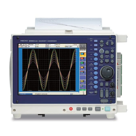
Hioki 8861 Instruction manual


Contents
i
Contents
Introduction.................................................................................1
Confirming Package Contents....................................................2
Safety Information......................................................................3
Operating Precautions................................................................5
Chapter 1
Overview__________________________________ 11
1.1 Product Overview and Features .......................................11
1.2 Measurement Workflow ....................................................12
Chapter 2
Names and Functions of Parts ________________ 19
2.1 Panel Names and Functions .............................................19
2.2 Screen Types and Contents .............................................23
2.3 Basic Operations ...............................................................32
2.3.1 To Change Settings ................................................................32
2.3.2 Entering Text and Numbers ....................................................33
2.3.3 Viewing Recorded Data ..........................................................35
Chapter 3
Measurement Preparations___________________ 37
3.1 Installation & Connection Procedures ...............................37
3.2 Connecting Cables and Probes ........................................38
3.3 Loading Recording Paper
(With a Printer Module Installed)........................................42
3.4 Connecting the Power Cord ..............................................45
3.5 Grounding the Instrument’s Functional Earth ...................45
3.6 Turning the Power On and Off ..........................................46
3.7 Setting the Clock ...............................................................48
Chapter 4
Basic Operations ___________________________ 49
4.1 Pre-Measurement Inspection ............................................49
4.2 Operation Workflow ..........................................................50

Contents
ii
4.3 Recording Simple Waveforms ..........................................51
4.4 Actual Measurement and Analysis ...................................54
Chapter 5
Saving & Loading Data ______________________65
5.1 Recording (Storage) Media ...............................................66
5.2 Using PC Cards ................................................................67
5.3 Data that can be Saved & Loaded ....................................68
5.4 Saving Procedures and Contents .....................................70
5.5 Data Saving ......................................................................71
5.6 Data Loading ....................................................................74
Chapter 6
Printing ___________________________________75
6.1 Printing Methods and Contents ........................................76
6.2 Printing While Recording (Auto Print) ...............................77
6.3 Manual Printing (PRINT Key) ...........................................78
6.4 To Print a Detailed Settings List .......................................79
Chapter 7
Maintenance and Service ____________________81
7.1 Troubleshooting ................................................................81
7.2 Cleaning ............................................................................84
Appendix ________________________________ A 1
Appendix 1 Waveform Screen Display & Icons..............................A 1
Appendix 2 Overview of Settings and Functions............................A 2
Appendix 3 Common Questions.....................................................A 7
Index ________________________________Index 1

Introduction
1
Thank you for purchasing the HIOKI “Model 8860/ 8861 Memory HiCorder."
To obtain maximum performance from the instrument, please read this manual
carefully, and keep it handy for future reference.
In this document, the “instrument” means the Model 8860 or 8861 Memory
HiCorder.
The following documents are provided with this instrument. Refer to them as
appropriate for your application.
Registered trademarks
Windows is a registered trademark of Microsoft Corporation in the United States
and/or other countries.
If you encounter problems during operation
Introduction
Document Description
1Quick Start Manual
(This document)
Read this first.
It describes preparations for use, basic operating pro-
cedures and usage methods.
2Input Module Guide
To connect input modules and measurement
cables, and when making input channel set-
tings;
this Guide describes the optional input modules, relat-
ed cable connection procedures, and their settings
and specifications.
3Instruction Manual To obtain setting details;
this Manual describes details of the functions and op-
erations of the instrument, and its specifications.
4Analysis Supplement The supplement describes usage of the cal-
culation functions to analyze measurement
data.
If you want to know a mea-
surement workflow
"1.2 Measurement Workflow" (⇒p. 12)
For operation overviews:
"Chapter 3 Operation Overview" in the Instruction
Manual
For screen configurations "2.2 Screen Types and Contents" (⇒p. 23)
"2.2 Screen Organization" in the Instruction Manual
For input module connec-
tions and channel setting
procedures Input Module Guide
When an error is displayed "Appendix 1 Error Messages" in the Instruction
Manual
When measurement prob-
lems occur, or for general
measurement questions
"Appendix 3 Common Questions" (⇒p. A7)
"Before returning for repair" (⇒p. 82)

Confirming Package Contents
2
Confirming Package Contents
1 Quick Start Manual
2 Input Module Guide
3 Instruction Manual
4 Analysis Supplement
........................................One each
Application CD
(Communications Manual)...........1
This instrument: Model 8860/ 8861 Memory
HiCorder (8860: 4-module, 8861: 8-module)
Confirm that these contents are provided.
Accessories
Power Cord.............................................1
Input Cable Labels...................................1
(If a printer module is installed)
For Model 8995 A4 Printer Unit:
Model 9231 Recording Paper...........1 roll
Paper Roll Holders ...........................1 pair
For Model 8995-01 A6 Printer Unit:
Model 9234 Recording Paper............1 roll
Paper Roll Axle........................................1
Other options specified when ordered
For information about options:
See "Appendix 5 Options" in the Instruction Manual
When you receive the instrument, inspect it carefully to ensure that no damage occurred
during shipping. In particular, check the accessories, panel switches, and connectors.
If damage is evident, or if it fails to operate according to the specifications, contact your
dealer or Hioki representative.

Safety Information
3
This manual contains information and warnings essential for safe operation of
the instrument and for maintaining it in safe operating condition. Before using it,
be sure to carefully read the following safety precautions.
The following symbols in this manual indicate the relative importance of cautions
and warnings.
Safety Information
This instrument is designed to comply with IEC 61010 Safety Standards,
and has been thoroughly tested for safety prior to shipment. However, mis-
handling during use could result in injury or death, as well as damage to
the instrument. Be certain that you understand the instructions and pre-
cautions in the manual before use. We disclaim any responsibility for acci-
dents or injuries not resulting directly from product defects.
Safety Symbols
In the manual, the symbol indicates particularly important information that
the user should read before using the instrument.
The symbol printed on the instrument indicates that the user should refer
to a corresponding topic in the manual (marked with the symbol) before
using the relevant function.
Indicates a burn hazard if touched directly.
Indicates DC (Direct Current).
Indicates AC (Alternating Current).
Indicates both DC (Direct Current) and AC (Alternating Current).
Indicates a grounding terminal.
Indicates the ON side of the power switch.
Indicates the OFF side of the power switch.
Indicates that incorrect operation presents an extreme hazard that
could result in serious injury or death to the user.
Indicates that incorrect operation presents a significant hazard that
could result in serious injury or death to the user.
Indicates that incorrect operation presents a possibility of injury to the
user or damage to the instrument.
Indicates advisory items related to performance or correct operation
of the instrument.

Safety Information
4
Other Symbols
S
ymbols in text
Indicates the prohibited action.
(⇒p. ) Indicates the location of reference informa-
tion.
Indicates quick references for operation
and remedies for troubleshooting.
*Indicates that descriptive information is
provided below.
[ ] Screen labels such as menu items, page
titles, setting items, dialog titles and but-
tons are indicated by square brackets [ ].
CURSOR
(Bold
characters)
Bold characters within the text indicate
operating key labels.
Unless otherwise specified, “Windows” represents Win-
dows 95, 98, Me, Widows NT4.0, Windows 2000, or Win-
dows XP.
Mouse operation terminology
Click: Press and quickly release the left button of the
mouse.
Right-click: Press and quickly release the right button of
the mouse.
Double click: Quickly click the left button of the mouse
twice.
Drag: While holding down the left button of the
mouse, move the mouse and then release the
left button to deposit the chosen item in the
desired position.
Activate: Click on a window on the screen to activate
that window.
We define measurement tolerances in terms of f.s. (full scale) values, with the following meanings:
f.s. (maximum display value or scale length)
The maximum displayable value or scale length. This is usually the name of the currently selected range.
In this instrument, the maximum displayable value is the range (V/div) times the number of divisions (20)
on the vertical axis. Example: For the 1 V/div range, f.s. = 20 V
Accuracy
This instrument complies with CAT II safety requirements.
This instrument’s input modules comply with CAT I or CAT II safety requirements.
To ensure safe operation of measurement instruments, IEC 61010 establishes safety standards for vari-
ous electrical environments, categorized as CAT I to CAT IV, and called measurement categories. These
are defined as follows.
CAT I: Secondary electrical circuits connected to an AC electrical
outlet through a transformer or similar device.
CAT II: Primary electrical circuits in equipment connected to an
AC electrical outlet by a power cord (portable tools,
household appliances, etc.)
CAT III:Primary electrical circuits of heavy equipment (fixed
installations) connected directly to the distribution panel,
and feeders from the distribution panel to outlets.
CAT IV:The circuit from the service drop to the service entrance, and to the power meter and primary over-
current protection device (distribution panel).
Higher-numbered categories correspond to electrical environments with greater momentary energy. So a
measurement device designed for CAT III environments can endure greater momentary energy than a
device designed for CAT II.
Using a measurement instrument in an environment designated with a higher-numbered category than
that for which the instrument is rated could result in a severe accident, and must be carefully avoided.
Never use a CAT I measuring instrument in CAT II, III, or IV environments.
The measurement categories comply with the Overvoltage Categories of the IEC60664 Standards.
Measurement categories (Overvoltage categories)
The applicable measurement category is determined by the input module being used. Refer to “Applicable Standards”
in "Chapter 5 Specifications" in the Input Module Guide for the applicable measurement categories.
Operating Precautions
5
Follow these precautions to ensure safe operation and to obtain the full benefits
of the various functions.
• Before using the instrument the first time, verify that it operates normally to
ensure that the no damage occurred during storage or shipping. If you find
any damage, contact your dealer or Hioki representative.
• Before using the instrument, make sure that the insulation on the probes and
connection cords is undamaged and that no bare conductors are improperly
exposed. Using the instrument in such conditions could cause an electric
shock, so contact your dealer or Hioki representative for replacements.
Operating temperature and humidity: 0 to 40°C at 20 to 80% RH (non-conden-
sating)
However, the operating temperature range may depend on the options used.
Temperature and humidity range for guaranteed accuracy:
23±5°C, 20 to 80%RH
Operating Precautions
Before Use
Instrument Installation
Operating Conditions Operating Temperature
While changing the battery in the Model 9719 Memory Back-
up Unit 10 to 40°C
While using the Model 8995 A4 Printer Unit, 8995-01 A6
Printer Unit, 9716 FD Drive or 9718 HD Unit 5 to 40°C
Model 9717 MO Unit 5 to 35°C
Avoid the following locations that could cause an accident or damage
to the instrument.
Exposed to direct sun-
light
Exposed to high tem-
perature
In the presence of cor-
rosive or explosive
gases
Exposed to liquids
Exposed to high hu-
midity or condensa-
tion
Exposed to strong
electromagnetic fields
Near electromagnetic
radiators
Exposed to high lev-
els of particulate dust Subject to vibration

Operating Precautions
6
Installing
• The instrument should be operated only with the bottom or rear side down-
wards.
• Vents must not be obstructed.
At least 50 mm
At least 50 mm spacing
on all sides
When using the optional printer, provide enough space for ejected recording
paper or use the Model 220H Paper Winder (optional recording paper auto
winder).
Handling the Instrument
• Do not allow the instrument to get wet, and do not take measurements
with wet hands. This may cause an electric shock.
• Never modify the instrument. Only Hioki service engineers should disas-
semble or repair the instrument. Failure to observe these precautions
may result in fire, electric shock, or injury.
• To avoid damage to the instrument, protect it from physical shock when trans-
porting and handling. Be especially careful to avoid physical shock from drop-
ping.
• Use the handle to carry the instrument.
See "Chapter 2 Names and Functions of Parts" (⇒p. 19)
• When the Model 8958 16-Ch Scanner Unit is installed, do not lift up on the
connector section of the unit. The connector section could be damaged.
Handling the Cords and Probes
• Avoid stepping on or pinching cables, which could damage the cable insula-
tion.
• To avoid breaking the cables and probes, do not bend or pull them.
• To avoid damaging the power cord, grasp the plug, not the cord, when unplug-
ging it from the power outlet.
Use only the specified connection cables. Using a non-specified cable may
result in incorrect measurements due to poor connection or other reasons.

Operating Precautions
7
For additional information about input modules, their connections and
measurement precautions, refer to the Input Module Guide.
Before Connecting
Before turning power on
• Before turning the instrument on, make sure the supply voltage matches
that indicated on the its power connector. Connection to an improper
supply voltage may damage the instrument and present an electrical haz-
ard.
• To avoid electrical accidents and to maintain the safety specifications of
this instrument, connect the power cord only to a 3-contact (two-conduc-
tor + ground) outlet.
Installing and removing input modules
• To avoid electric shock accident, before removing or replacing an input
module, confirm that the instrument is turned off and that the connection
cords are disconnected.
• The mounting screws must be firmly tightened or the input module may
not perform to specifications, or may even fail.
• To avoid the danger of electric shock, never operate the instrument with
an input module removed. To use the instrument after removing an input
module, install a blank panel over the opening of the removed module.
Using an Optional Printer
When the instrument is not to be used for a long time, or when transport-
ing
To avoid straining some parts of the printer, and to prevent dirt adhering to the
print head, set the print head to its lowered position (so that the print head rests
against the print roller).
After storing the printer without use for a long time, inspect the following before
use:
1. Move the head raising lever up and down.
2. Perform test printing (printer check) three or four times.
When printing
• Avoid slow printing as much as possible in hot or humid environments. Other-
wise, printer life may be severely shortened.
• Please use only the specified recording paper. Using non-specified paper may
not only result in faulty printing, but printing may become impossible.
• If the recording paper is skewed on the roller, paper jams may occur. If the
recording paper is skewed on the roller, paper jams may result.
• Printing is not possible when the recording paper is loaded upside-down.
Refer to "3.3 Loading Recording Paper (With a Printer Module Installed)" (⇒p.
42) for printing precautions.

Operating Precautions
8
Input and Measurement Precautions
The maximum input voltage and maximum rated voltage to ground
(between the grounds of the input terminals and the instrument, and
between inputs of other analog modules) of each input module and exter-
nal input terminals are shown below. To avoid risk of electric shock and
damage to the instrument, be careful to not exceed these ratings. The max-
imum rated voltage to ground is the same regardless of whether an input
attenuator or similar device is used.
Input Terminal (Input Module) Maximum Input Voltage*1Maximum Rated Voltage
to Ground*2
8936 Analog Unit 400 V DC max 370 V AC/DC
8956 Analog Unit 400 V DC max 300 V AC/DC
8946 4-Ch Analog Unit 30 V rms/ 60 V DC 30 V rms / 60 V DC
8938 FFT Analog Unit 400 V DC max 370 V AC/DC
8957 High Resolution Unit 400 V DC max 300 V AC/DC
8959 DC/RMS Unit 400 V DC max 370 V AC/DC
8937 Voltage/Temp Unit 30 V rms/ 60 V DC 30 V rms / 60 V DC
8939 Strain Unit 10 V DC max 30 V rms / 60 V DC
8960 Strain Unit 10 V DC max 33 V rms / 70 V DC
8940 F/V Unit
(BNC jacks and sensor re-
ceptacles)
30 V rms / 60 V DC
(BNC jack)
30 V rms / 60 V DC
(Sensor receptacle terminals)
Uninsulated
8947 Charge Unit*3(BNC jack)
30 V rms / 60 V DC (BNC jack)
30 V rms / 60 V DC
8958 16-Ch Scanner Unit 40 V DC max 33 V rms / 70 V DC
9322 Differential Probe
(CATII)
2000 V DC, 1000 V AC
(CAT III)
600 V AC/DC
With grabber clips
1500 V AC/DC (CAT II)
600 V AC/DC (CAT III)
With alligator clips
1000 V AC/DC (CAT II)
600 V AC/DC (CAT III)
I/O Terminals Maximum input voltage Maximum rated voltage
to ground
EXT.SMPL
EXT.TRIG
PRINT/EXT.IN3
STOP/EXT.IN2
START/EXT.IN1
-2 to 7 V DC
Uninsulated
TRIG OUT/CAL
NG/EXT OUT2
GO/EXT OUT1
-20 to 30 V DC,
500 mA max,
200 mW max
This Instrument Input Module
GND
*1
*2
H
L
*2
“xxx V AC/DC” indicates an RMS
value, and “xxx V DC max” indi
-
cates an instantaneous value.
(Input modules other than the
Model 8947 Charge Unit)
This Instrument Input Module
GND
*3
*2
H
L
*2
*1
H
L
BNC
Miniature
Connector
Common
(8947 Charge Unit) *1.Maximum input voltage
*2.Maximum rated voltage to
ground
*3.Maximum applied electric
charge
500 pC(high-sensitivity side,
6
ranges),
50,000 pC (low-sensitivity
side, 6 ranges)

Operating Precautions
9
Use the original packing materials when transporting the instrument, if possible.
The optional Model 9723 and 9724 Carrying Cases are available for shipping the
Models 8860 and 8861, respectively.
To avoid accidents in the event of a short circuit, when measuring com-
mercial mains voltage using the Model 8936, 8938, 8956, 8957 or 8959 input
modules, connection should be made only at the secondary side of a
breaker. Never make connections at the primary side of a breaker, as unre-
stricted current flow could cause a serious accident if a short circuit
occurs.
When measuring AC mains voltage, for example, using a power transformer, be
sure to connect the ground terminal of the power transformer to ground.
Using a power transformer (PT)
This Instrument Input Module
GND
H
LInput
Power transformer with ground terminal
Ground (Earth terminal of power source, or equivalent)
PT
Power transformer ground terminal
Power transformer without ground terminal
GND
H
L
Input
Ground (Earth terminal of power source, or equivalent)
PT
This Instrument Input Module
Correct measurement may be impossible in the presence of strong magnetic
fields, such as near transformers and high-current conductors, or in the pres-
ence of strong electromagnetic fields such as near radio transmitters.
Shipping precautions
To avoid damage, observe the following when shipping the instrument:
• Remove the PC cards before shipping.
• If the optional printer module is installed, remove the paper. If the paper is left
in the instrument, the paper-handling components may be damaged by vibra-
tion.

Operating Precautions
10

1.1 Product Overview and Features
11
Overview Chapter 1
1.1 Product Overview and Features
Recording various analog
signals
Measurements are
provided in combina-
tion with optional input
modules,cablesandclamp
probes depending on the
application.
Voltage, Current, Tempera-
ture, Acceleration, Vibra-
tion, Frequency, Stress, etc.
Automatic and manual saving, loading
and file management of measurement
data (⇒p. 65)
Data saving and loading are available with optional PC
Cards. Also, using optional proprietary drives, saving
and loading can be performed on floppy diskettes, MO
or hard disk. Data on storage media can be managed
with this instrument.
"Chapter 10 Saving/Loading Data & Managing Files" in
the Instruction Manual
Memory capacity can be expanded with optional mem-
ory boards. (This option must be specified when order-
ing.) 8860: 32 Megawords to 1 Gigaword, Model 8861:
64 Megawords to 2 Gigawords
Automatic and manual
printing of measurement
data (⇒p. 75)
Measurement data can be printed
with the optional A4 or A6 internal
printer and special recording pa-
per. Printing is also available on
an external USB printer.
"Chapter 11 Printing" in the
Instruction Manual
Recording logic signals
Measures using optional logic
probes.
Mixed analog and
logic recording is
possible.
Remote control and data collection
The instrument can be connected to a PC for measure-
ment data analysis and remote control.
"Chapter 13 Communications Settings" in the
Instruction Manual
External Control
The instrument can be controlled by external signals.
"Chapter 14 External Control" in the Instruction Manual
Easy entry of text and numerical values
Screen operations and character input can be per-
formed by connecting a commonly available mouse
or keyboard.
"3.3 Common Operations" in the
Instruction Manual
Input Module Guide
X-Y Display ZoomSplit-Screen Display
Numerical Calculations Gauge and Level Monitor
Displays
In this case
• Viewing waveforms before and
after an anomaly.
• Capturing the waveform of an
intermittent anomaly.
• Recording multiple signal lines
over an extended period.
• Acquiring measurement data for
processing on a PC.
Overlay
Sheet Display
Analysis
Measures with functions
that support analytical
applications
Memory Function
Recorder Function
Real-Time Saving Function
FFT Function
Cursor Measurements
Many other functions are provided in addition to these. Refer to "Appendix 2 Overview of Settings and Functions"
(⇒p. A2) and "Chapter 1 Overview" in the Instruction Manual.

1.2 Measurement Workflow
12
1.2 Measurement Workflow
1 Install & Connect Connect the instrument to the measurement object, an
d
turn power on.
See"Chapter 3 Measurement Preparations" (⇒p. 37) in this manua
l
See"Instrument Installation" (⇒p. 5) in this manual
Details of input module connections and connection cables:
See"Chapter 2 Connections" in the Input Module Guide
See"3.6 Turning the Power On and Off" (⇒p. 46) in this manual
To set the clock:
See"3.7 Setting the Clock" (⇒p. 48)
2 Make Instrument Settings Make appropriate instrument settings to acquire the mea
-
surement data.
See"Chapter 4 Basic Operations" (⇒p. 49) in this manual, (Auto
-
matic setting is available (⇒p. 51))
For details:
See"Chapter 4 Measurement Configuration Settings" in th
e
Instruction Manual
See"Chapter 3 Input Channel Settings" and "Chapter 4 Logic Inpu
t
Settings" in the Input Module Guide
See"Chapter 6 Trigger Settings" in the Instruction Manual
See"Chapter 7 Waveform Display Settings" in the Instruction Manua
l
See"Chapter 5 Saving & Loading Data" (⇒p. 65) and "Chapter
6
Printing" (⇒p. 75) in this manual,
"Chapter 10 Saving/Loading Data & Managing Files" and "Chap
-
ter 11 Printing" in the Instruction Manual
Turn power on
Setting measurement
configuration
Set trigger criteria
3 Measure
Install the instrument
Select the input channels
Start recording
Analysis
Optionally save and print
Press the START key to start measuring.
Measurement data is recorded by the instrument with the selected se
t-
tings.
Measurement data recording stops automatically after th
e
preset period, or when you press STOP.
(Setting contents determine what causes measurement to stop.)
Analyze measurement data (⇒p. 61).
Save and print measurement data as occasion demands.
See"Chapter 8 Waveform Screen Monitoring and Analysis" in th
e
Instruction Manual, and Analysis Supplement
5 Finish
Connect
Stop recording
4 Analyze, Save and Print
Select the Screen Layout
Turn the power off
Set saving and printing
conditions
Overall workflow and summary
If you don’t want to shut down completely (in order to measur
e
again immediately), press the STANDBY/ON key to activate th
e
standby state (⇒p. 47).
(To record specified waveforms)
(To change the layout of the Waveform screen)
(To automatically save and print while
measuring)
See"3.3.6 Starting and Stopping Measurement" in the Instructio
n
Manual
(As occasion demands)

1.2 Measurement Workflow
13
Operation Overview: Recording Analog Waveforms
For more details, refer to "3.1 Measurement Workflow" in the Instruction Manual.
Also refer to "Appendix 2 Overview of Settings and Functions" (⇒p. A2) and "Appendix 3 Common Ques-
tions" (⇒p. A7).
Installation & Connections Install the input modules and cables required for
measurement (⇒p. 37).
Refer to the Input Module Guide for details about input mod-
ules and cables.
Power ON
Function Selection Select the function according to your application.
See "Function Selection" (⇒p. 29)
• Memory function
To record relatively fast signals from µs to minutes
• Recorder function
To record relatively slow signals at low speeds from ms to
hours
Record instantaneous
waveforms Long-term measurements
Memory (MEM)
(Sampling point
recording)
Recorder (REC)
(Envelope recording)
Measurement Configuration
Settings Make settings on the Status Settings screen.
Press the SET key to open the Settings screen
Press the SUB MENU keys to select the
menu
Press the SHEET/
PAGE keys to select
the [Use Ch] page
Verify the channel(s)
to be used
Press the SHEET/PAGE keys to select the
[Basic] page
1Set the timebase (horizontal axis)
2Set the recording length
1
2
See"4.2 Setting Measurement Configuration (Status Set-
tings Screen)" in the Instruction Manual

1.2 Measurement Workflow
14
Input Channel Settings Make settings on the Channel Settings screen.
Press the SUB MENU keys to select the
menu
Press the SHEET/PAGE keys to select the
[One Ch] page
3Select the Unit (module) and Channel
4Select the measurement range (vertical axis)
Make input-module-related settings
5Perform zero adjustment
6(As occasion demands)
Set the scaling, waveform colors and
zero position
Trigger Settings (If you want to record a specific waveform, such as an
anomaly)
Set on the Trigger Settings screen.
Press the SUB MENU keys to select the
menu
7Set the trigger mode
8Set the trigger criteria (AND/OR)
9(Memory)
Set pre-trigger (Recorder)
Set trigger timing
10 Set each trigger source
4
6
3
5
See"Chapter 5 Input Channel Settings" and "7.1 Makin
g
Input Waveform Display Settings (Analog Waveforms
)"
in the Instruction Manual
"Chapter 3 Input Channel Settings" in the Input Modu
le
Guide
(after warm-up
)
9
10
7
8
See"Chapter 6 Trigger Settings" in the Instruction Manual
Analog or Logic Trigger
External
Trigger
Timer Trigger
Default setting:
(Memory) [Auto]
(Recorder) [Single]
Default setting: [OR]
Default setting: All [Off]

1.2 Measurement Workflow
15
Display Sheet Settings (If you want to change the layout of the waveform
screen to show any combination of channels)
Set on the Sheet Settings screen.
Press the SUB MENU keys to select the
menu
11
(As occasion demands)
Select the Screen Layout
Set the number screen divisions and the
split-screen layout
12 Select the channels to display
Saving Settings (If you want to save data)
Set on the Save Settings screen.
Press the SUB MENUs key to select the
menu
13 Select automatic or manual saving
Specify the saving destination
14 Select what to save
12
S
ee"Chapter 7 Waveform Display Settings" in the Instructio
n
Manual
Combination
of display
channels
11
Up to 32 channels can be
displayed per sheet.
WhenusingmultipleMode
l
8958 16-Ch Scanner
Units, channels are auto-
matically assigned to
sheets.
(Example: Auto Save)
S
ee"Chapter 10 Saving/Loading Data & Managing Files"
in
the Instruction Manual
13
14
Verify that storage media
h
as been inserted.
W
hen saving manually,
s
ettings can be changed
a
fter measurement.
Default setting:
Auto Save [Off],
Manual Save [Selection
Save]

1.2 Measurement Workflow
16
Printing Settings (If you want to print data)
Set on the Print Settings screen.
Press the SUB MENU keys to select the
menu
Press the SHEET/PAGE keys to select the
[Printer] page
15 Select automatic or manual printing
Press the SHEET/PAGE keys to select the
[Print Items] page
16 Select what you want to print
Start of Measurement Press the START key (the green LED lights).
End of Measurement Press the STOP key.
Recording stops after acquiring the specified length
(the green LED goes off).
Press twice to stop immediately.
If [Single] trigger is selected, recording stops automatically
after acquiring the specified data length.
Data Analysis Analysis on the waveform screen.
See"Chapter 8 Waveform Screen Monitoring and Analysis"
in the Instruction Manual
Optionally save and print Press the SAVE key to save. (Manual saving)
Press the PRINT key to print. (Manual printing)
Power OFF Remove the cables from the measurement object,
and turn the power off.
16
See"Chapter 11 Printing" in the Instruction Manual
15
Verify that the paper is
loaded correctly.
When printing manually,
settingscanbemadeafter
measurement.
Default setting:
Auto Print [Off]
Manual Print [Selection
Print]
Data acquisition
Save & Print (when Auto enabled)
Waveform data is erased when power is turned off. However, measurement settings are retained.
To retain waveforms with power off, the optional Model 9719 Memory Backup Unit is required.
This manual suits for next models
1
Table of contents
Other Hioki Data Logger manuals

Hioki
Hioki PW3360-30 User manual

Hioki
Hioki LR8431-20 User manual

Hioki
Hioki HiLogger 3145-20 User manual

Hioki
Hioki LR8432-20 User manual

Hioki
Hioki LR8400-20 User manual

Hioki
Hioki LR5011 User manual

Hioki
Hioki PW3365 User manual

Hioki
Hioki LR5051 User manual

Hioki
Hioki HiCORDER MR8880 User manual

Hioki
Hioki 3910-20 User manual

Hioki
Hioki MICRO HiCORDER 8206-10 User manual

Hioki
Hioki LR5041 User manual

Hioki
Hioki LR8410-20 User manual

Hioki
Hioki LR8520 User manual

Hioki
Hioki 8420-51 Instruction manual

Hioki
Hioki LR5051 User manual

Hioki
Hioki 3631-20 User manual

Hioki
Hioki LR8431-20 User manual

Hioki
Hioki LR8400-20 User manual

Hioki
Hioki LR8431-20 User manual