Sibata MT-11 D User manual

CODE 080200-1100
Thank you for purchasing this product.
●This operation manual contains important safety information and product handling instructions.
●Before use, read through this operation manual to ensure safe and proper use.
Operation Manual (for Main Unit)
Fit Tester

2
Product Contents
Check the contents of the package before using the product.
Main unit....................................................................................................... 1 pc
AC adapter (plug attached, with 3 other plugs) ............................................. 1 pc
Sampling tube (pair tube) 1.5 m .................................................................. 2 pcs
Alcohol cartridge (alcohol wick attached, installed in alcohol fill case)........... 1 pc
Alcohol fill case ............................................................................................. 1 pc
Storage cap (attached to main unit) .............................................................. 1 pc
Replacement alcohol wick .......................................................................... 2 pcs
Tube connector........................................................................................... 2 pcs
Test guide ................................................................................................. 10 pcs
Strap clip ...................................................................................................... 1 pc
High-performance zero check filter ............................................................... 1 pc
Tube Joint Set Type M 100 pairs/set........................................................... 1 box
Tube Joint Attachment Tool Type M ............................................................ 1 box
Stylus pen (attached to main unit)................................................................. 1 pc
USB cable type A-B 1.5 m............................................................................. 1 pc
USB flash drive............................................................................................. 1 pc
External output connector cap (attached to main unit) .................................. 1 pc
Soft case ...................................................................................................... 1 pc
Warranty................................................................................................... 1 copy
If any contents of the package are damaged or missing, contact the distributor where you
purchased the product.
About this Operation Manual
The operation manual for this product is in two sections. Read the operation manual (PC
Software User Guide) for information on how to use the PC software.
Information in this operation manual is subject to change without notice in the interest of
product improvement.
Every effort has been made to ensure that the information contained in this operation manual
is correct. If you discover any errors or omissions, however, please contact your Sibata
representative.
The copyright of this operation manual belongs to Sibata Scientific Technology Ltd. This
operation manual, or any part thereof, may not be reproduced, reprinted, or altered in any form
without prior written permission from Sibata Scientific Technology Ltd.
Disclaimers
Be aware that the measurements provided by this product are only for evaluating the fit of a
respirator during a Fit Test. The respirator fit will vary depending on the circumstances. The Fit
Test measurement value is not intended for use when calculating the exposure of individuals to
actual toxic substances. Accordingly, understand that Sibata bears absolutely no responsibility if
it is used for purposes other than the above-mentioned evaluation.

3
Table of Contents
1Safety Precautions.........................................................................................4
Users (Important)...............................................................................................4
Graphical Symbols ............................................................................................4
Caution Labels...................................................................................................6
2About this Product.........................................................................................7
Overview............................................................................................................7
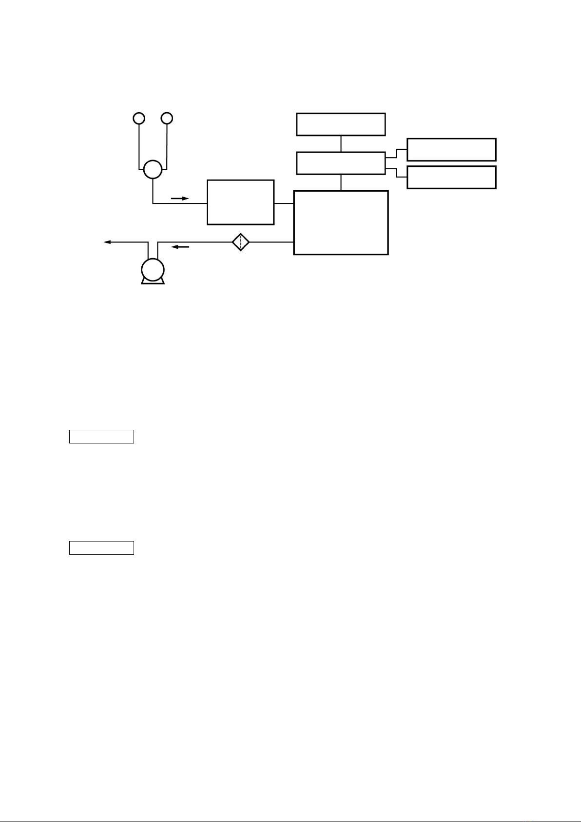
Measurement Principle......................................................................................7
Precautions......................................................................................................10
Names of Parts................................................................................................12
3Preparation ...................................................................................................13
Types of Data and Measurement Results.......................................................13
Preparation of the Alcohol ...............................................................................13
Supplying Power, Startup, and Shutdown.......................................................16
Main Menu Screen ..........................................................................................17
3-4-1 Checking the Version Information......................................................17
Basic Screen Configuration and Operations...................................................18
Preparing for Measurement.............................................................................21
3-6-1 Connecting the Sampling Tube..........................................................21
3-6-2 Selecting How to Connect to the Respirator......................................22
3-6-3 Checking the Particle Concentration in the Environmental Air..........24
3-6-4 If Condensation Develops in the Test Guide or Sampling Tube........24
3-6-5 Checking and Cleaning the Suction Ports .........................................25
4Measurement................................................................................................26
Measurement Modes.......................................................................................26
Configuration of the Measurement Mode Screen ...........................................27
Daily Check Mode ...........................................................................................29
Fit Test Mode ...................................................................................................31
Fit Check Mode ...............................................................................................36
Training Mode..................................................................................................38
5Settings.........................................................................................................40
Setting Menu ...................................................................................................40
Fit Test Settings ...............................................................................................40
Fit Check Settings ...........................................................................................43
Daily Check Settings .......................................................................................44
Training Settings..............................................................................................45
Date/Time Settings ..........................................................................................46
Basic Settings..................................................................................................47
Touch Panel Correction ...................................................................................50
6Database .......................................................................................................51
Database Menu ...............................................................................................51
Database Selection .........................................................................................52
Database Management ...................................................................................53
People Data.....................................................................................................54
Respirator Data ...............................................................................................55
Operator Data..................................................................................................56
7External Output ............................................................................................57
8Maintenance .................................................................................................59
Inspections and Maintenance .........................................................................59
Operational Check with Clean Air ...................................................................61
Consumables...................................................................................................61
9Troubleshooting ...........................................................................................62
10 Main Specifications......................................................................................64
11 Warranty and Repairs ..................................................................................67

4
1 Safety Precautions
The warnings and instructions in this operation manual are provided to ensure that the product is
used safely, to prevent injury to the operator and others, and to prevent property damage. All of
the precautionary information is important for ensuring safety. Therefore, be sure to read and
understand the information thoroughly before using the product and observe it during use.
Users (Important)
This product should only be operated by trained and experienced operators that understand the
specialized technology and dangers involved. Untrained or currently being trained operators
should only operate the product under close supervision by a person that is already trained or
has sufficient specialized experience.
This operation manual is written assuming the product will be operated by a person that
understands the risks of operating the product.
Graphical Symbols
The degree of danger involved in using the product without observing the indicated
precautionary information is indicated by one of two labels: WARNING or CAUTION. Always
observe the precautionary information indicated with these labels, which is important for
ensuring safety.
Labels Indicating Degrees of Damage or Injury
Indicates a potentially hazardous situation which, if not avoided,
could result in serious injury or death.
Indicates a potentially hazardous situation which, if not avoided,
may result in injury or equipment damage.
This product is not explosion proof, so do not use it near combustible or flammable materials.
Do not subject the product to strong impacts or drops. Otherwise, a malfunction or accident
could result.
Never attempt to disassemble or modify the product. Otherwise, a malfunction or accident could
result.
This product is designed for indoor use. Use this product indoors at an altitude no higher than
2000 m.
If there are lightning strikes nearby, turn OFF the power, and unplug the power cord from the
outlet. Otherwise, an electric shock or fire could result.
If a problem occurs during operation, immediately stop operating the product, and remove the
cause. If it is determined that the product caused the problem, turn OFF the power switch,
unplug the power cord from the outlet, and then contact the distributor where you purchased
the product or your Sibata representative. Never operate the product if it is not functioning
normally. Also, never allow anyone other than a qualified service engineer to disassemble or
modify the product. Otherwise, a malfunction or accident could result.
Do not operate this product while it is wrapped or covered by a cloth or bedding. Otherwise, a
fire or malfunction could result from trapped heat.

5
Do not get water or other liquids on the product. Otherwise, a malfunction could result.
Be sure to comply with the recommended operating temperature range (15 to 30 °C).
Otherwise, a malfunction or accident could result.
Only use the AC adapter that is provided with this product.
Do not use the product with power supplies other than single-phase 100 to 240 V AC ± 10 %.
Also, do not use an overloaded electrical outlet. Otherwise, an electric shock or fire could result.
Contact the distributor where you purchased the product or your Sibata representative if you
will be using the equipment at a voltage outside of these specifications.
Do not use a damaged power cord or loose power supply outlet. Doing so could result in a fire,
electric shock, or other hazards.
Do not touch the power cord, plug or outlet with wet hands. Otherwise, an electric shock could
result.
Never attempt to connect to the connectors on the back of the main unit using wire or other
metal objects, or any other method not specified in this manual. Otherwise, a fire or equipment
damage could result.
Do not insert wire or other foreign objects into the suction ports. Otherwise, a malfunction could
result.
Do not use this product in an environment where it is exposed to toxic gases, acidic or alkaline
substances, or anything other than air. Otherwise, a malfunction, explosion, or fire could result.
If this product is used in a manner other than that specified by Sibata, the protective
functionality built into it could be lost.
When moving the product, do not swing it. Otherwise, a malfunction or injury could result.
Install this product at a level, stable location. Otherwise, a malfunction, accident, or operational
error could result.
Do not install or store the product where it is exposed to strong direct sunlight, or near a fire.
Otherwise, a product malfunction or failure could result.
Do not climb or place heavy objects on the product. Otherwise, a product deformation,
malfunction, or accident could result.
Do not wash the product directly in water. Otherwise, an electric shock, fire, or malfunction
could result.
Unplug the power cord from the outlet when the product is not in use. Otherwise, a fire or
malfunction could result.
Unplug the power cord from the outlet when cleaning the product. Otherwise, a fire or
malfunction could result.
Do not use any alcohol other than ethanol, or organic solvents (such as paint thinner or
benzene) for cleaning it. Otherwise, the paint could peel off.
The AC adapter is not liquid resistant, so do not clean it with ethanol.
Always grip the plug to unplug the power cord. Pulling on the cord could damage the cord and
cause an electric shock or fire.
Do not step on or place heavy objects on the power cord. Otherwise, a disconnection, electric
shock, or fire could result.

6
Be careful not to bump into the suction ports or the other protrusions. Although the corners and
other potentially hazardous areas on this product have been smoothed, be careful during
handling. Otherwise, an injury could result.
The materials used in this product (including accessories and optionally available parts) could
induce an allergic reaction. If you have any allergies, be sure to check that you are not allergic
to any of the materials (see p.66). Avoid using the product if you are allergic to any of the
materials.
Be careful not to catch your hands or feet on the sampling tubes, power cord, or USB cable.
Otherwise, a malfunction or injury could result.
Be careful not to pierce your hand or fingers with the tip of the tube joint attachment tool. Do not
point the tip toward anyone. Otherwise, an injury could result.
Do not allow this product to fall. Otherwise, a malfunction or injury could result.
If continuous measurements are taken, the alcohol concentration in the room will increase.
Ventilate the area as needed.
Depending on the measurement environment, long-term exposure may adversely affect your
health. In this case, stop the measurements immediately, and leave the measurement
environment until you recover.
Use the USB cable provided with this product, or another USB cable no longer than 3 m.
Do not block the cooling fan. Otherwise, a malfunction or operational error could result.
Caution Labels
Caution labels are affixed to the back of this product. Comply with the cautions noted therein.
AVOID SHOCK
Do not subject the product to strong impacts or drops. Otherwise,
a malfunction or accident could result.
KEEP DRY
Do not touch the power cord, plug or outlet with wet hands. Do not
wash the product directly in water. Otherwise, an electric shock,
fire, or malfunction could result.

7
2 About this Product
Overview
This measuring instrument checks the degree of adhesion when the user wears a respirator
(disposable or replaceable type). Measurements can be performed in a general indoor space.
Individuals have differently shaped faces. Many different types of respirators are sold by
respirator manufacturers, so select a respirator that is a good fit to your face when it is worn. To
fully draw out the performance of the respirator, the correct handling of the respirator, and
whether it adheres sufficiently against the face must be considered.
This product is used to measure the extent of adhesion between the face and the face contact
portion of the respirator when the respirator is worn If there is a gap between them, indoor dust
will leak into the respirator in accordance with the extent of this gap. With this product, the extent
of this leakage can be measured. By figuring out the best respirator attachment method to
minimize the extent of this leakage, respirator wearers themselves can fully draw out the
inherent performance of the respirator, or the effect of wearing the respirator.
This product uses a condensation nucleus counter (CNC) as a detector. It counts the number of
particles larger than a pre-specified size, existing in a given volume of air sampled. This product
automatically samples air and switches between the inside and outside measurements based on
preset conditions.
In measuring the extent of leakage (leakage percentage), first the air near the respirator is
sampled, and the particle concentration in the indoor air (outside the respirator) is measured.
Next, air is sampled from inside the respirator being worn and the particle concentration in this
air are measured. Then a leakage percentage is found from the ratio of these two values.
Quantification of the degree of adhesion is performed in this way.
This product is operated using a (pressure sensitive) touch panel, and is easy to operate thanks
to the color LCD. It can also be operated by connecting external input devices such as a USB
mouse and USB keyboard.
Measurement Principle
Counting the Number of Particles
The number of particles in the sampled air is counted by an instrument called a condensation
nucleus counter (CNC).
When particles (of dust) suspended in air are illuminated by light, the particles scatter the light
(Mie scattering). The optical system and electrical circuit are configured to ensure that each time
one particle passes through, an electrical signal pulse from the scattered light generates one
spike, enabling the number of particles passing through to be counted. At the same time, the
intensity (brightness) of the scattered light is strongly correlated with the size of the particles.
Generally speaking, only very weak scattered light is obtained from small particles under 0.3 μm
in size, making their detection difficult. Accordingly, a liquid (isopropyl alcohol in the case of this
product) is condensed onto the particles, enlarging their apparent size until even tiny particles on
the order of 20 nm can be detected from the scattered light. In other words, a CNC is an
instrument that performs counts by condensing vapor with tiny particles as the nucleus.

8
Quantification of the Degree of Adhesion of the Respirator
The method used to quantitatively assess the degree of adhesion between the respirator and the
face of the person wearing the respirator is as follows.
If there is a gap that particles can just pass through between the face of the wearer and the
respirator, depending on the size of this gap, particles outside the respirator will penetrate inside
the respirator during respiration. The degree of adhesion of the respirator to the face can be
expressed numerically by the ratio between the concentration of these particles in the room air
(outside the respirator) near the respirator, and the concentration inside the respirator.
With this product, this extent of adhesion is expressed as a leakage percentage, indicated by the
following formula.
=
×100
: Leakage [%]
: Particle concentration outside the respirator (outside)
: Particle concentration inside the respirator (inward)
The fit factor/protection factor, an index showing the cleanliness of the air inside the respirator
with respect to the air outside the respirator, is found from the leakage percentage using the
following formula.
=
100
: Fit Factor, Protection Factor
The overall leakage percentage is calculated based on the arithmetic mean leakage percentage
of a multiple number of measurements taken.
The overall fit factor/overall protection factor is determined by substituting the arithmetic-mean
leakage percentage of individual measurements (overall leakage percentage) into the above
formula (harmonic mean of fit factors/protection factors of individual measurements)
=
1+
2+
3+ • • • +
=
100
=
100
1+
2+
3+ • • • +
=
1
1
+1
2
+1
3
+ • • • + 1
: Number of measurements
: Overall Leakage [%]
: Overall Fit Factor, Overall Protection Factor

9
Block Diagram
Purge
A purge time is established to exchange the air remaining inside the detector with air subject to
measurement when measurement starts and during switching between OUTSIDE and MASK.
During measurement, purges are performed in the following sequences.
Example 1
Alternating measurements of OUTSIDE and MASK
OUTSIDE purge (1) → OUTSIDE measurement (1) → MASK purge (1) → MASK measurement (1)
→ OUTSIDE purge (2) → OUTSIDE measurement (2) → MASK purge (2) → MASK measurement (2)
→• • •• • •• • •• • •• • •• • •• • •• • •• • •• • •• • •• • •• • •• • •• • •• • •• • •• • •• • •• • •• • •
→ OUTSIDE purge n → OUTSIDE measurement n → MASK purge n → MASK measurement n
Example 2
OUTSIDE measurements are performed at the beginning and end of the sequence. In
between, MASK measurements are performed consecutively.
(“Outside sample times” is set to “Twice in Fit test”.)
OUTSIDE purge (1) → OUTSIDE measurement (1) → MASK purge (1) → MASK measurement (1)
→ MASK measurement (2) → MASK measurement (3) → • • • → MASK measurement n
→ OUTSIDE purge (2) → OUTSIDE measurement (2)
OUTSIDE MASK
Touch panel
Control circuit
Solenoid valve
RS-232C output
Condensation
nucleus counter
(CNC)
USB
Classifier
Pump
Exhaust
Filter

10
Precautions
Cautions When Carrying the Product
This measuring instrument is equipped with a detector and processor, so be careful not to bump
or swing it when moving or handling it.
Opening and Closing the Mirror
When opening and closing the mirror, support the main unit with one hand.
Connecting to the Respirator
If the tube joint (push-on ring type) is selected for the connection to the respirator, the respirator
used for measurement cannot be used for actual work. Use the test guide to check the degree of
adhesion of a respirator that will actually be worn (Fit Test without Fit Check, Training, or
respirator selection) (see p.22). Note that the test guide cannot be used in Fit Tests for respirator
selection. For replaceable respirators, use a sampling adapter and simulated face sold by
respirator manufacturers.
Handling the Tube Joint Attachment Tool
Be careful not to pierce your hand or fingers with the tip of the tube joint attachment tool. Do not
point the tip toward anyone. Otherwise, an injury could result.
Measurement
Before performing measurements, check via a medical interview by a physician that the subject
has no history of serious diseases of the respiratory organs or circulatory organs.
Instruct the subject that if they feel breathless when wearing the respirator, it is ok to remove it at
any time. In that case, the operator should stop the measurements immediately, and assist the
subject with removing the respirator.
Depending on the measurement environment, long-term exposure may adversely affect your
health. In this case, stop the measurements immediately, and leave the measurement
environment until you recover.
Handling the Sampling Tube
If this product is used for an extended period, condensation may develop inside the test guide
and the tube. Condensation will have an impact on the measurement results, so if water droplets
are evident inside a tube, dry it thoroughly, or replace it with a dry tube before performing
measurements.
Operating the Touch Panel
The touch panel in this product is pressure sensitive. To operate it, lightly touch one time only on
a single point on the screen.
A malfunction may result if you touch multiple places simultaneously. Also be careful not to touch
too hard, as you risk damaging the touch panel.

11
Face Contact
There are some parts, such as the test guide, tube joint, etc., that touch or may touch your face.
If you have any allergies, be sure to check that you are not allergic to any of the materials (see
p.66). Avoid using the product if you are allergic to any of the materials.
Laser
This product is a class 1 laser product. The information on the built-in laser is as follows.
Wavelength: 658 nm
Output: 40 mW (laser rating); 15 mW (controlled)
Beam divergence angle: 10 × 20° FWHM
Pulse width and frequency: CW
Using and adjusting the control unit or performing any
procedures other than those specified in this manual may
cause exposure to hazardous radiation.
Pollution Degree and Overvoltage Category
The pollution degree and overvoltage category for this product are as follows.
Pollution Degree 2
Overvoltage Category II

12
Names of Parts
Speaker
Power supply connector
RS232C external
output connector
(with cap)
USB connectors
Type A: 2 ports, for USB flash drive, USB mouse, and USB keyboard
Type B: 1 port, for connecting a PC
Stylus pen
Cooling fan
Mirror
Color LCD touch panel
(pressure sensitive type)
Suction ports
“MASK”
“OUTSIDE”
[POWER] switch
Alcohol cartridge insertion port

13
3 Preparation
Types of Data and Measurement Results
Data used for measurement include People, Respirator, Operator, and Protocol (Fit Test
settings). These can be created using PC software and stored on a PC, transferred to a
database file on a USB flash drive, or used in stand-alone measurements with this main unit.
These types of data can also be created with the main unit. However, deletion of protocol data,
as well as the editing or deletion of other types of data, can only be performed using PC
software.
These types of data can be created without using a USB flash drive, but they cannot be stored.
In terms of the measurement modes, measurement results from the Fit Test mode, Fit Check
mode, and Daily Check mode are saved in the USB flash drive database file. The saved
measurement results can be transferred to the PC using PC software, for use in creating and
printing reports.
These measurements can be performed without using a USB flash drive, but the measurement
results cannot be stored.
If the measurements are performed from the PC software, the measurement results are saved
on the PC.
Preparation of the Alcohol
With this product, isopropyl alcohol (2-propanol) is used for the measurements.
Purchase these separately.
Be sure to read the SDS before use.
Turn the alcohol cartridge counterclockwise to release the lock, and
then remove it from the alcohol fill case.
Keep the alcohol cartridge clean after
it is removed.
Otherwise, a malfunction could result.
Use high purity reagent grade isopropyl alcohol, or one with a purity of at least 99.5 %.
A malfunction could result if a lower quality is used.
An alcohol wick is inserted into the alcohol cartridge at the time of shipment. Dry or replace the alcohol
wick if the measurement time shortens or the wick becomes dirty and changes color (see p.60).

14
Inject alcohol up to the line at the bottom of the
alcohol fill case. Insert the alcohol cartridge,
and turn it clockwise until you feel a click.
Leave it as is for 2 to 3 minutes.
The alcohol will permeate the alcohol wick inside the alcohol cartridge.
Check that the main unit is unplugged. Remove the storage cap from
the alcohol cartridge insertion port (see p.12).
Remove the alcohol cartridge from the alcohol
fill case. Shake it gently to remove any excess
alcohol, and then attach it by inserting it into the
alcohol cartridge insertion port.
Attach the storage cap that has been removed from the main unit
to the alcohol fill case.
If you overfill it, the alcohol might overflow when
the alcohol cartridge is re-inserted.
If a new or sufficiently dry alcohol wick is used, it will absorb more alcohol than when continuously
used, and there will be almost no alcohol in the alcohol fill case. In this case, remove the alcohol
cartridge, and re-permeate it by replenishing with additional alcohol.

15
After using the main unit, check that the power is OFF.
Then remove the storage cap from the alcohol fill case.
Remove the alcohol cartridge, and store it
by inserting it into the alcohol fill case.
Attach the storage cap to the alcohol cartridge insertion port.
Do not leave the alcohol cartridge inserted into the main unit
as is when not in use or during shipment.
Otherwise, the alcohol might seep inside, leading to malfunctions.

16
Supplying Power, Startup, and Shutdown
Connect the DC plug from the AC adapter to the power connector on the back of the main unit.
Then connect the power cord at the other end to an AC outlet.
If some problem is detected with the product, discontinue use immediately, unplug the power
cord from the outlet, and contact the distributor where you purchased the product or your Sibata
representative.
Startup
To turn ON the power, check that the power cord has been inserted into an AC outlet. Then
touch the [POWER] switch on the front of the unit. The switch lamp will light up, and the startup
procedure will begin.
After startup, the Main Menu screen is displayed, and the USB flash drive and database are
checked.
If there is a previously used database on the USB flash drive, this is automatically selected.
To change the database, touch the Database selection key to display the database selection
screen (see p.52).
If a USB flash drive is not found, the DEMO database built into the main unit is automatically
selected.
Shutdown
To turn OFF the power, touch the [POWER] switch
on the front. When a confirmation message is
displayed, select [OK]. After the shutdown
procedure finishes, the switch lamp will go out and
the power will turn OFF. Unplug the power cord
from the AC outlet.
The data might be corrupted if the power cord is
unplugged from the AC outlet before the main unit
turns OFF.
Only use the AC adapter that is provided with the product.
The pump will stop momentarily and the screen will darken, but if the switch lamp is still lit up, the
startup operation is continuing, so wait for it to complete.
Database selection key

17
Main Menu Screen
Touch [Fit Test], [Daily Check], [Fit Check], or [Training] to perform measurements in each
mode. [Settings] is used to configure the measurement mode settings and other settings, and
[Database] is used to manage the database and other data.
Remote Display
When communication with the PC software starts, the unit identification number is displayed at
the bottom of the screen (in the subarea), and operation of the touch panel will be disabled. (See
the Operation Manual (PC Software User Guide) for how to use the PC software.)
Standby Display when Switching Screens
This mark may be displayed during operation. At this point, the
product is in the process of switching screens. Be aware that if
you perform another operation while this mark is displayed, the
product may malfunction. If it is not operating properly, turn
OFF the [POWER] switch, and then turn it ON again. If the
problem persists, the product may be malfunctioning. So,
discontinue use immediately and contact the distributor where
you purchased the product or your Sibata representative.
3-4-1 Checking the Version Information
Touch [Ver. info.] to display the version information screen. Touch [Main Menu] on the
version information screen to return to the Main Menu screen.

18
Basic Screen Configuration and Operations
The following shows the basic configuration of the screen.
Title area This displays the icons and title of the screen being displayed, and the
current date and time.
In the measurement mode screen, this also displays icons related to the
measurement status.
Title bar This is distinguished by color from the screen being displayed.
In the measurement mode screen, this also displays measurement related
information.
Field In the measurement mode screen, this indicates the progress, the results
data, and the operation keys.
In the settings screen and database screen, this is used to display and
input various items.
Subarea This displays various operation keys related to data selection and
changing screens.
If the screen is changed by touching [Settings] or [***Data] in each
measurement mode, a key will be displayed for returning to the original
screen.
During communication with the PC software, the unit identification number
appears here. (See the Operation Manual (PC Software User Guide).)
Operation keys When a key is touched, the operation noted on the key is performed, or the
screen displayed changes.
Title area Title barField
Operation keys
Subarea

19
These are the basic operations in the selection and input screens.
Selection and input
With this item, touching the mark at the right edge enables selection from a
pull down list. Touching the character display area at the left displays a
keyboard that can be used to input characters.
Selection only
This item can only be selected from a pull down list.
Select
This item is set by selecting or clearing a checkbox.
If the checkbox is selected, it is ON. If the checkbox is cleared, it is OFF.
Input only
This item is entered by direct input. Touch this to display a numerical
keypad or a keyboard.
Settings configured
Items before the changes or items that have been configured are
displayed in blue.
Provisional setting
If a setting is changed, it will become provisionally set. The changed item
will change color from blue to yellow, and keys for applying or canceling
the changes will be displayed.
[Save]
When an item has been provisionally set, this key is displayed for applying
the changes. Touch this to apply the provisional settings details. The
settings area changes from yellow back to blue and the key disappears.
[Cancel]
When an item has been provisionally set, this key is displayed for
canceling the changes. Touch this to cancel the provisional settings and
return to the state before the changes. The settings area changes from
yellow back to blue and the key disappears.
Factory reset key
Touch this to return the settings to the factory defaults (see p.21).
With the Fit Test settings only, factory reset affects the protocol being set,
not the Fit Test settings as a whole (see p.40).
Page key
When the settings details cover multiple pages, touch this key to move
between pages.
Once a setting is changed and becomes a provisional setting, its provisional status will not
change even if you change it again to the original setting. Apply or cancel the changes.
Selection and input
Selection only
Select
Input only
Save key
Provisional settingSettings configured
Cancel key
Factory reset key Page key

20
A numerical keypad is displayed for inputting only numerical values or figures.
Name of Settings Displays the details for the value being configured, and its settings range.
Close key Touch this to cancel the entry and close the numerical keypad.
Clear key Touch this to set the value entered to “0”.
Delete key Touch this to delete the last digit entered.
Enter key Touch this key to accept the numerical value and close the numerical
keypad. If the number entered is smaller than the settings range, it will be
replaced by the lower limit value. If it is larger, it will be replaced by the
upper limit value.
A keyboard is displayed for inputting characters.
Switches between direct input and
alphanumerical character input.
Switches between capital and
small case characters.
Select a character conversion
candidate.
Switches between alphabetical
characters and numerals.
Applies the character conversion.
Deletes the previous character.
Deletes the next character.
Name of settings (settings range)Close key
Clear key
Delete key
Enter key
Table of contents
Other Sibata Test Equipment manuals