SiboTech ENB-302MI User manual
EtherNet IP / Modbus Gateway
ENB-302MI
User Manual
REV 1.1
Sibotech Automation Co., Ltd
Technical support: +86-021-5102 8348
E-mail: support@sibotech.net

www.sibotech.net
- 2 -
Table of Contents
1 About the Gateway...........................................................................................................................................- 4 -
1.1 Function...................................................................................................................................................- 4 -
1.2 Feature..................................................................................................................................................... - 4 -
1.3 Technical specification........................................................................................................................ - 4 -
2 Rapid Application Guide................................................................................................................................ - 6 -
2.1 Connecting the power.......................................................................................................................... - 6 -
2.2 Connect serial devices......................................................................................................................... - 6 -
2.3 Ethernet connection..............................................................................................................................- 7 -
2.4 Configuration Switch........................................................................................................................... - 8 -
2.5 Installing software................................................................................................................................ - 8 -
3 Hardware Description......................................................................................................................................- 9 -
3.1 Appearance............................................................................................................................................. - 9 -
3.2 Indicators................................................................................................................................................ - 9 -
3.3 Configuration switches......................................................................................................................- 10 -
3.4 Interface.................................................................................................................................................- 10 -
3.4.1 Power interface........................................................................................................................ - 10 -
3.4.2 Ethernet interface.....................................................................................................................- 11 -
3.4.3 RS-485 interface...................................................................................................................... - 11 -
4 Instructions of Configuration Software.....................................................................................................- 13 -
4.1 Notes before configurating............................................................................................................... - 13 -
4.2 User interface....................................................................................................................................... - 14 -
4.3 Operation of equipment view...........................................................................................................- 16 -
4.3.1 Equipment view interface......................................................................................................- 16 -
4.3.2 Operation mode of equipment view....................................................................................- 17 -
4.3.3 Operation types of equipment view.................................................................................... - 17 -
4.4 The operation of configuration view.............................................................................................. - 18 -
4.4.1 Interface of Ethernet configuration view........................................................................... - 18 -
4.4.2 Interface of subnet configuration view...............................................................................- 19 -
4.4.3 Interface of node configuration view..................................................................................- 21 -
4.4.4 Interface of command configuration view........................................................................ - 21 -
4.4.5 Notes View................................................................................................................................- 23 -
4.5 Conflict detect......................................................................................................................................- 23 -
4.5.1 Operation of command list....................................................................................................- 24 -
4.5.2 Operation of memory mapping area................................................................................... - 24 -
4.6 Hardware communication.................................................................................................................- 25 -
4.6.1 Ethernet configuration............................................................................................................- 25 -
4.6.2 Upload configuration..............................................................................................................- 26 -
4.6.3 Download configuration........................................................................................................ - 28 -

www.sibotech.net
- 3 -
4.7 Load and save configuration............................................................................................................ - 29 -
4.7.1 Save the configuration project..............................................................................................- 29 -
4.7.2 Load the configuration project............................................................................................. - 29 -
4.8 Output excel document......................................................................................................................- 29 -
4.9 Debug.....................................................................................................................................................- 30 -
5 EtherNet/IP Connection Parameters...........................................................................................................- 33 -
6 Typical Application........................................................................................................................................ - 34 -
7 Installation........................................................................................................................................................- 35 -
7.1 Mechanical Dimensions.................................................................................................................... - 35 -
7.2 Installation............................................................................................................................................ - 35 -
8 Attention........................................................................................................................................................... - 37 -
9 Copyright Information...................................................................................................................................- 38 -
10 Related Products...........................................................................................................................................- 39 -

www.sibotech.net
- 4 -
1 About the Gateway
1.1 Function
Through the conversion between EtherNet IP protocol and Modbus protocol of ENB-302MI, Modbus serial
devices can access EtherNet IP network, bi-directional and easily exchange data.
1.2 Feature
Redundant Power Supply
Two independent RS485 interfaces 1KV optical isolation
Ethernet 10/100M adaptive
IP address conflict detection
Modbus network debugging
Easy to use configuration software GT-123
1.3 Technical specification
[1] EtherNet / IP network is independent with two Modbus networks;
[2] Ethernet 10/100M adaptive;
[3] Support IP addresses conflict detection function;
[4] Support the ODVA Standard EtherNet / IP communication protocol;
[5] Two serial RS485 interfaces, half-duplex, and baud rate support: 1200, 2400, 4800, 9600, 19200, 38400,
57600, 115200; parity mode support: none, odd, even, mark, space; 1 or 2 stop bits;
[6] ENB-302MI act as master at the side of Modbus network and support 01H, 02H, 03H, 04H, 05H, 06H, 0FH,
10H function codes, can be configured up to 48 Modbus commands for each RS485 interface; Modbus function

www.sibotech.net
- 5 -
codes 03H, 04H, 06H and 10H support "Byte swap" function, and it can help users solve the problem of data
format between two different networks;
[7] Two independent RS485 interfaces 1KV optical isolation;
[8] The maximum number of input and output bytes of EtherNet / IP:
Maximum number of input bytes: 512Bytes
Maximum number of output bytes: 512Bytes
[9] Power supply: 24VDC (11V ~ 30V), 90mA (24VDC);
[10] Working temperature: -20 ℃~ 60 ℃, relative humidity: 5% ~ 95% (no condensation);
[11] Dimensions: 40mm (width) × 125mm (height) × 110mm (depth);
[12] Installation: 35mm rail;
[13] Protection class: IP20;
[14] Test standard: EMC test standards
www.sibotech.net
- 6 -
2 Rapid Application Guide
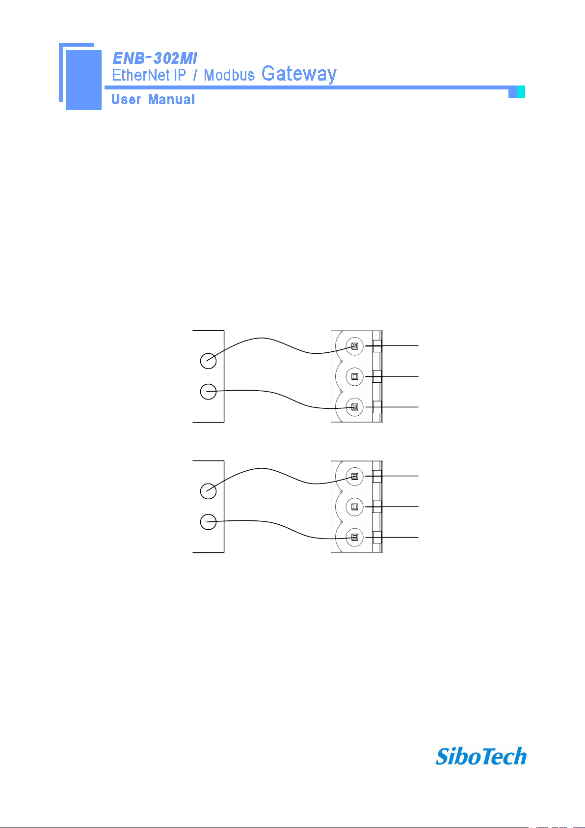
2.1 Connecting the power
DC 24V power supply, dual power supply interface, a redundant function, users can use one or two power supply.
If you are using two power supply, when the way in which the power fails, the other way you can continue to
supply power to ensure normal operation.
Power supply wiring as shown below:
GND
NC
24V+
1
2
3
GND
24V+
DC power: +24V Ⅰ
Power interface of ENB-302MI
GND
NC
24V+
1
2
3
GND
24V+
Optionally be connected
Must be connected
Power interface of ENB-302MI
(the other)
DC power: +24V Ⅱ
2.2 Connect serial devices
RS485 connection as shown below:

www.sibotech.net
- 7 -
B+
A-
GND
1
2
3
485+
485-
RS485 device 1
RS485 interface
RS485 device 2
RS485 device 3
485+
485-
485+
485-
…
In order to prevent signal reflection and interference in RS485 multipoint communication, adding one
terminal resistor at the both farthest ends of the line is necessary, and the argument is 120Ω 1/2W.
Note: There is no internal termination resistor in the RS485 interface of ENB-302MI.
2.3 Ethernet connection
Ethernet interface apply RJ-45 connector, 10/100M adaptive.
www.sibotech.net
- 8 -
Pin
Signal Description
S1
TXD+,Tranceive Data+, Output
S2
TXD-,Tranceive Data-, Output
S3
RXD+,Receive Data+, Input
S4
Bi-directional Data+
S5
Bi-directional Data-
S6
RXD-,Receive Data-, Input
S7
Bi-directional Data+
S8
Bi-directional Data-
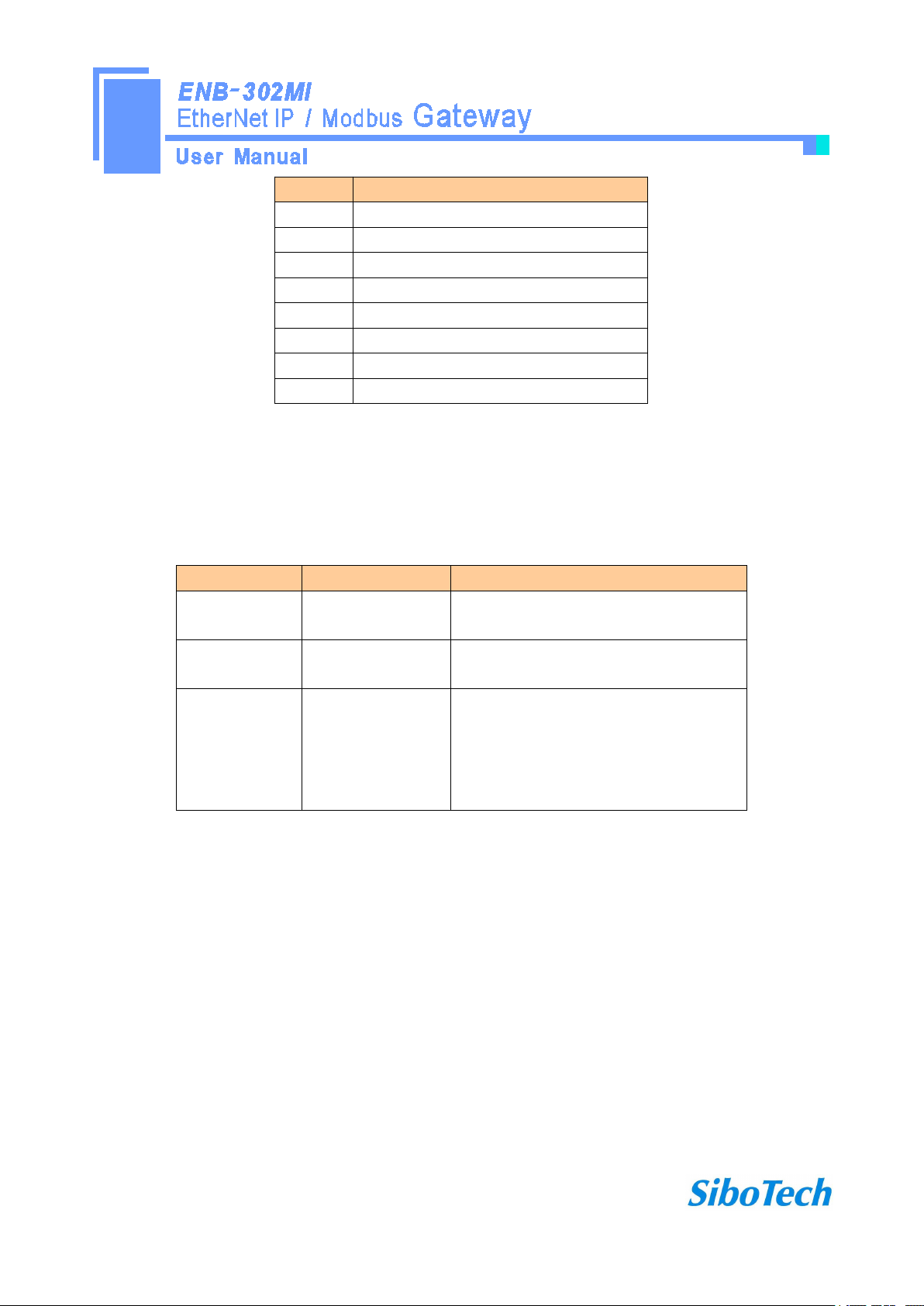
2.4 Configuration Switch
Configuration switches located on the bottom of the gateway, set the mode bit (bit 1) to 0 (Off), and set
function bit (bit 2) to 0 (Off), power (or restart) the device to work.
Mode bit (bit 1)
Function bit (bit 2)
Description
Off
Off
Operation mode, allowing read and write
configuration data
Off
On
Operation mode, read and write
configuration data against
On
Off or On
Configuration mode, IP address is fixed at
192.168.0.10, this mode can only read and
write configuration data, can not
communication between EtherNet / IP and
Modbus network
2.5 Installing software
Take the product CD into the computer CD drive, open the CD, install the configuration software GT-123.
You can easily follow the prompts to complete the installation. Then open the configuration software and finish
the configuration of ENB-302MI!
Note: The factory set of ENB-302MI is DHCP, if the network is no DHCP Server, you can set mode bit (bit
1)to 1(On), and restart ENB-302MI, then the fixed IP address of ENB-302MI is 192.168.0.10, mask is
255.255.255.0, gateway address is 192.168.0.1.
www.sibotech.net
- 9 -
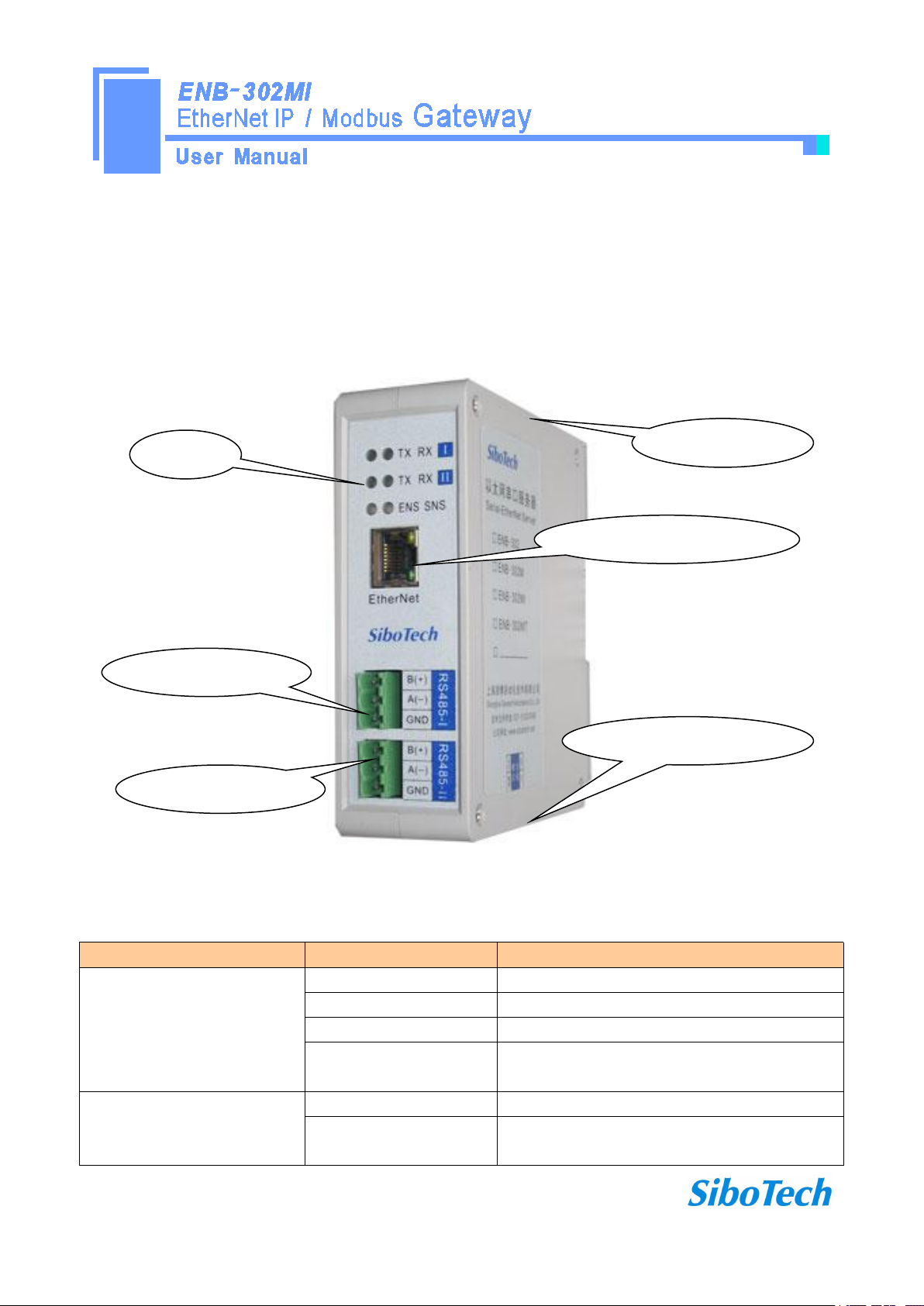
3 Hardware Description
3.1 Appearance
3.2 Indicators
Indicator
Status
Description
ENS
Always green
EtherNet / IP connection is established
Green flashing
EtherNet / IP connection is not established
Always red
IP address indicates a conflict
Red flashing
EtherNet / IP connection timed out; DHCP, BOOTP ,
IP address conflict detection
SNS
Always green
Modbus Communication normal
Always red
At least one Modbus network response timeout,
exception or error
Ethernet RJ-45 interface
RS-485interfaceⅠ
RS-485interfaceⅡ
Configuration switches
Power interface
Indicator
www.sibotech.net
- 10 -
Alternately flashing red
and green light
At least part of one Modbus network timeout, an
exception or error
ENS orange light and SNS
orange light
(orange light: Red and green
light at one time)
Light at one time
Start status
Flash alternately
Configuration mode
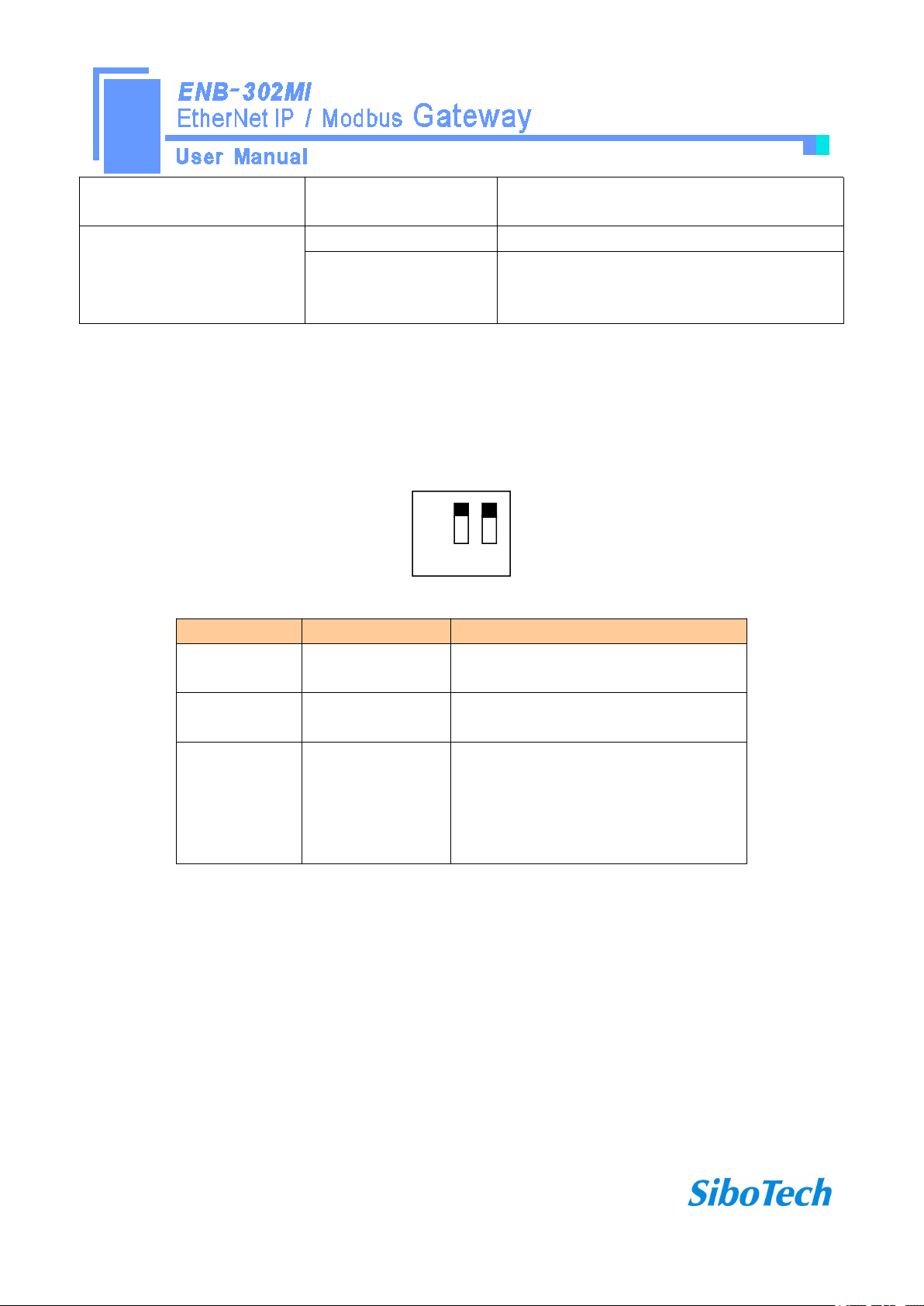
3.3 Configuration switches
Configuration switch locate on the bottom, bit 1 is mode select bit, bit 2 is function set bit.
Off
On 1 2
Mode bit (bit 1)
Function bit (bit 2)
Description
Off
Off
Operation mode, allowing read and write
configuration data
Off
On
Operation mode, read and write
configuration data against
On
Off or On
Configuration mode, IP address is fixed at
192.168.0.10, this mode can only read and
write configuration data, can not
communication between EtherNet / IP and
Modbus network
Note: Restart ENB-302MI after resetting the configuration and the configuration can take effect!
3.4 Interface
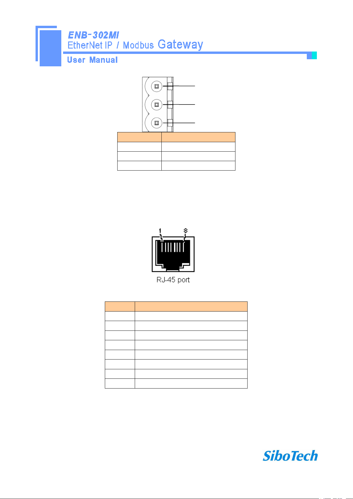
3.4.1 Power interface
ENB-302MI has two power interfaces, with power redundancy function, when one the way to power failure,
power can continue to supply the other way.
www.sibotech.net
- 11 -
GND
NC
24V+
1
2
3
引脚
功能
1
GND,
2
NC, no connection
3
24V+ , DC
3.4.2 Ethernet interface
Ethernet interface apply RJ-45 connector, 10/100M adaptive.
Pin
Signal Description
S1
TXD+,Tranceive Data+, Output
S2
TXD-,Tranceive Data-, Output
S3
RXD+,Receive Data+, Input
S4
Bi-directional Data+
S5
Bi-directional Data-
S6
RXD-,Receive Data-, Input
S7
Bi-directional Data+
S8
Bi-directional Data-
3.4.3 RS-485 interface
The RS-485 interface of ENB-302MI is standard, and the RS-485 characteristics of the product are shown
as follows:

www.sibotech.net
- 12 -
1. The basic characteristics of RS-485 transmission technology
①Network topology: Linear bus, there are active bus termination resistors at both sides.
②Transfer rate: 300 bps~115.2Kbps.
③Media: Shielded twisted-pair cable and also can cancel the shielding, depending on environmental
conditions (EMC).
④Site number: 32 stations per subsection (without repeater), and can up to 127 stations (with RS485
repeater).
⑤Plug connection: 3-pin pluggable terminal.
2. The main points on RS-485 transmission equipments installation
①All the equipments be connected with RS-485 bus;
②Subsection can be connected up to 32 sites;
③The farthest end of each bus has a termination resistor—120Ω 1/2W to ensure reliable operation of the
network.
Serial interface uses 3-pin pluggable terminal and users can wire it according to the wiring instructions on the
panel.
B+
A-
GND
1
2
3
Pin
Function
1
B+,RS485
2
A-,RS485
3
GND

www.sibotech.net
- 13 -
4 Instructions of Configuration Software
4.1 Notes before configurating
GT-123 is a product based on Windows platform, and used to configurate a variety of fieldbus gateway
devices, including PM-120, MD-21, SS-430, PM-160, ENB-302MI and other products. It can set related
parameters and commands of Modbus and other bus.
The document mainly introduces the use method of ENB-302MI.
Double-click the icon to enter the main interface of the software:
Choose "ENB-302MI" to enter configuration interface:
www.sibotech.net
- 14 -
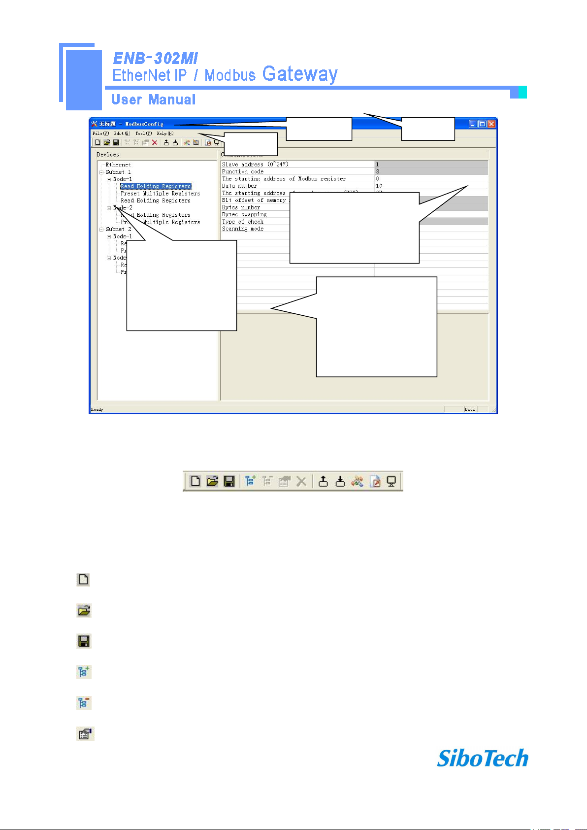
4.2 User interface
GT-123 interface include: title bar, menu bar, toolbar, status bar, equipment section, configuration section and
notes section.
Note: All the gray part in the software can not be changed.
www.sibotech.net
- 15 -
Toolbar is shown as below:
Functions separately from left to right are: new, open, save, add nodes, delete nodes, add commands, delete
commands, upload configuration, download configuration, conflict detect, output Excel configuration document
and debug.
New: Create a new configuration project
Open: Open a configuration project
Save: Save the current configuration
Add nodes: Add a Modbus slave node
Delete nodes: Delete a Modbus slave node
Add commands: Add a Modbus command
Equipment section: can
choose the operating
targets, including fieldbus
or sub-network and add
the nodes and commands.
Menu bar
Toolbar
Title bar
Configuration section: input
configuration parameters, gray
part can not be modified, while
white part can be modified.
Notes section: The specific
explanation to the nouns
appearing in the
configuration and
devices to help users to
understand and operate.

www.sibotech.net
- 16 -
Delete commands: Delete a Modbus command
Upload configuration: Read the configuration from the module and show it in the software
Download configuration: Download the configuration from the software to the module
Conflict Detect: Detect whether there is conflict in memory data buffer of the gateway
Output Excel document: Output the current configuration to local hard disk and save it as .xls file
Debug: For debugging Modbus communications, and defining the network fault.
4.3 Operation of equipment view
4.3.1 Equipment view interface
www.sibotech.net
- 17 -
4.3.2 Operation mode of equipment view
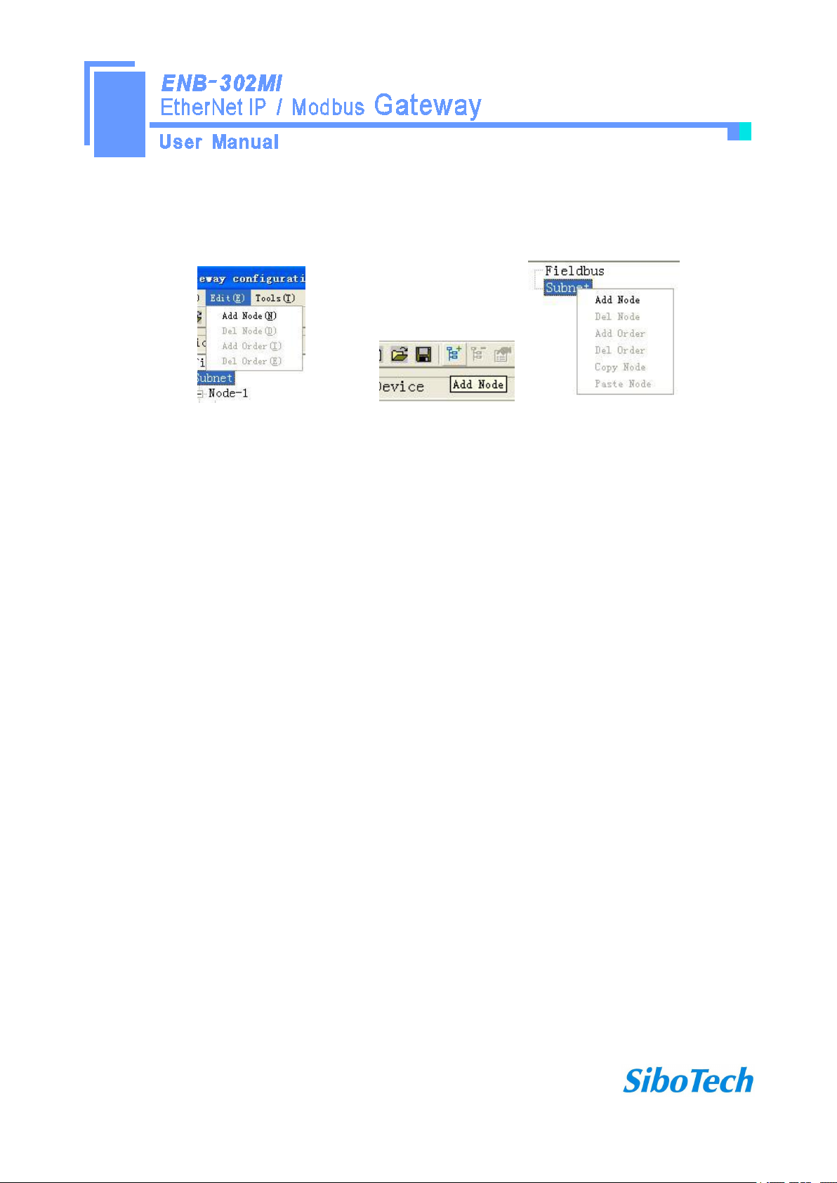
The equipment view supports three types of operation: Edit Menu, Edit Toolbar and Right click edit Menu.
4.3.3 Operation types of equipment view
1 Add nodes: Right click on subnet or existing nodes, and then perform the operation of adding a new node.
Then there is a new node named "new node" under subnet.
2 Delete nodes: Right click on the node to be deleted, and then perform the operation of deleting the node.
The node and its all commands will be deleted.
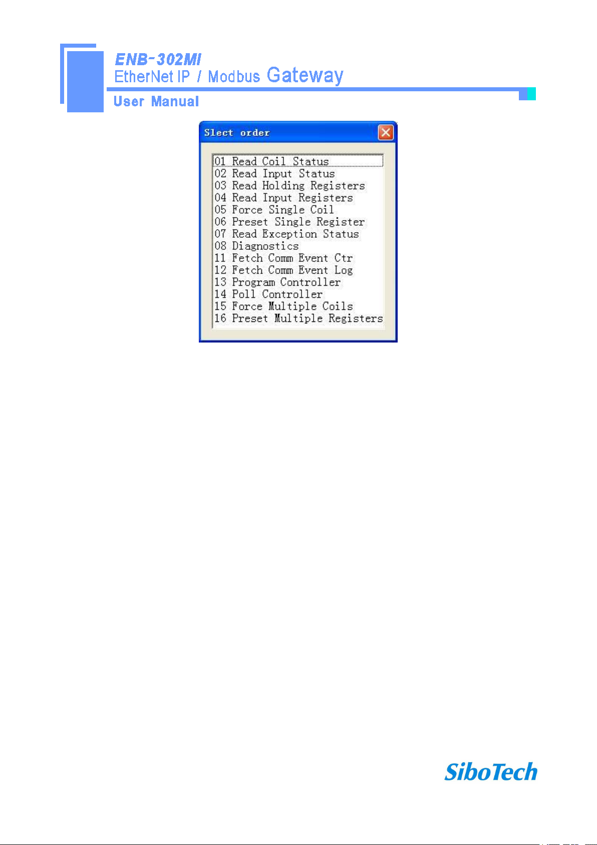
3 Add commands: Right click on the node, and then perform the operation of adding command to add a
command for the node. The dialog box will be shown as follow:
Currently, it supports the commands: 01, 02, 03, 04, 05, 06, 15 and 16.
Select the command: Double click the command
www.sibotech.net
- 18 -
4 Delete commands: Right-click on the command and then perform the operation of deleting the command.
5 Rename nodes: Left click on the node to be renamed, and then the edit status will be shown and you can
rename it.
4.4 The operation of configuration view
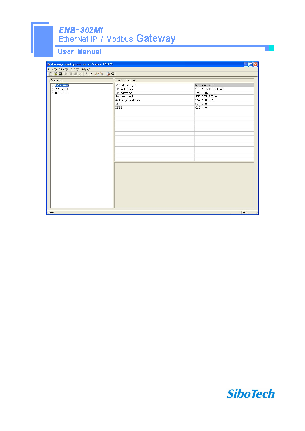
4.4.1 Interface of Ethernet configuration view
In the interface of device view, click Ethernet, and then the configuration view is shown as follows:
Configurable items include: IP setting method, IP address, subnet mask, gateway address, DNS1, DNS2.
IP setting method: static configuration, BOOTP, DHCP can be selected.
IP Address: Set the device IP address.
Subnet Mask: Set subnet mask of the device.
Gateway Address: Set gateway address.
DNS1: Set the device DNS1 address.
DNS2: Set the device DNS2 address.

www.sibotech.net
- 19 -
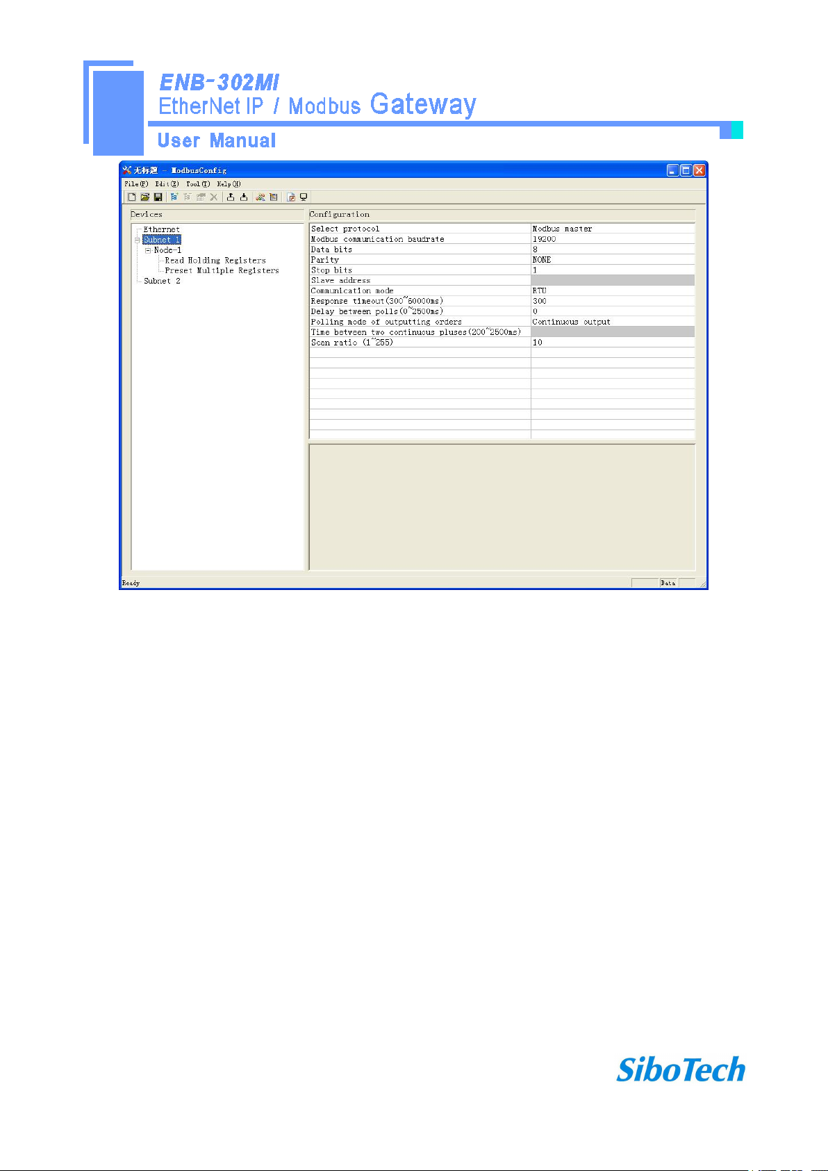
4.4.2 Interface of subnet configuration view
Protocol is Modbus master
Configurable parameters are shown as follows:
Modbus communication baud rate, Data bits, Parity check mode, Stop bit, Transmission mode, Response
timeout, Delay between polls, Polling mode of outputting commands, Time between two continuous pluses (the
polling mode of outputting commands is pulse output), Scanning ratio
Interface of configuration view is shown as follow:
www.sibotech.net
- 20 -
Modbus communication baud rate: There are 300, 600, 1200, 2400, 9600, 19200, 38400, 57600 and
115200bps to be selected.
Data bits: 8 bits
Parity check mode: There are none, odd, even, mark and space to be selected.
Stop bits: There are 1 and 2 to be selected.
Transmission mode: There are RTU and ASCII to be selected.
Response timeout: When the Modbus master send commands, the time waiting for response from the slave,
the range is 300~60000ms.
Delay between polls: After an command of Modbus having been sent and having received correct response,
the time before next command being sent, the range is: 0 ~ 2500ms.
Polling mode of outputting command:
Modbus writing command (output command) has 4 kinds of outputting modes: Continuous output, 0utput disable,
Change-of–state output, Pulse output, Communication port
Table of contents
Other SiboTech Gateway manuals


