SiboTech PCO-150S User manual

CANopen / Profibus-DP Gateway
PCO-150S
User Manual
REV 1.6
Sibotech Automation Co., Ltd
Technical Support: 021-5102 8348

User Manual
Profibus DP CANopen Gateway-/
PCO 150S
www.sibotech.net
1
Table of Contents
1 ABOUT THIS DOCUMENT..............................................................................................................................2
1.1 GENERAL............................................................................................................................................................... 2
1.2 IMPORTANT USER INFORMATION...................................................................................................................... 2
1.3 TERMS.................................................................................................................................................................... 2
2 ABOUT THE GATEWAY....................................................................................................................................3
2.1 PRODUCT FUNCTION .......................................................................................................................................... 3
2.2 FEATURE................................................................................................................................................................ 3
2.3 TECHNICAL SPECIFICATION .............................................................................................................................. 3
2.4 ATTENTION............................................................................................................................................................ 4
2.5 RELATED PRODUCTS........................................................................................................................................... 4
3 EXTERNALVIEW................................................................................................................................................5
3.1INDICATORS ........................................................................................................................................................... 6
3.2 DIP SWITCHES...................................................................................................................................................... 7
3.3 ROTARY SWITCH .................................................................................................................................................. 7
3.4 CONNECTORS ....................................................................................................................................................... 7
3.4.1 PROFIBUS-DP interface......................................................................................................................... 7
3.4.2 CANopen connector.................................................................................................................................. 8
3.5 OTHERS.................................................................................................................................................................. 9
3.5.1Power interface ............................................................................................................................................ 9
3.5.2 RS232 interface .......................................................................................................................................... 9
3.5.3 LED................................................................................................................................................................ 9
4 USE METHOD......................................................................................................................................................10
4.1 QUICK START ...................................................................................................................................................... 10
4.2 HARDWARE CONNECTION ............................................................................................................................... 10
4.3 SOFTWARE CONFIGURATION ........................................................................................................................... 10
4.4 RUN ...................................................................................................................................................................... 10
4.4.1 Data exchange mode............................................................................................................................... 10
4.4.2 Profibus-DP Data Module ..................................................................................................................... 11
5 STEP7 READ AND WRITE GATEWAY DATA......................................................................................15
6 INSTALLATION...................................................................................................................................................16
6.1 MECHANICAL DIMENSION .............................................................................................................................. 16
6.2 INSTALLATION .................................................................................................................................................... 16
7 FAILURES AND SUGGESTIONS................................................................................................................17
APPENDIX: USING STEP7 SET PROFIBUS-DP.....................................................................................18

User Manual
Profibus DP CANopen Gateway-/
PCO 150S
www.sibotech.net
1 About This Document
1.1 General
This document describes every parameters of the gateway PCO-150S and provides using methods and some
announcements that help users use the gateway. Please read this document before using the gateway.
For further information, documentation etc., please visit the SiboTech website: http://www.sibotech.net/En/
1.2 Important user information
The data and examples in this document can not be copied without authorization. Sibotech maybe upgrades
the product without notifying users.
is the registered trade mark of SiboTech Automation Co., Ltd.
The product has many applications. The users must make sure that all operations and results are in
accordance with the safety of relevant field, and the safety includes laws, rules, codes and standards.
1.3 Terms
zCAN: CAN bus is a kind of serial data communication protocol being developed by German BOSH from
early 1980s for solving the data exchange method between modern car control and test instruments.
zCANopen: CANopen protocol is one of the standard being defined by CAN-in-Automation (CiA),
CANopen defined application layer (Application layer), communication description (CiA DS-301), device
description (CiA DSP-4XX) , all cable and port (CiA DSP-303) and so on. In OSI model, the relationship
between CAN standard and CANopen protocol is shown as follow:
2

User Manual
Profibus DP CANopen Gateway-/
PCO 150S
www.sibotech.net
3
2 About the Gateway
2.1 Product Function
Connects device with CANopen master interface to Profibus-DP network, and establishes communication
between them.
2.2 Feature
¾Support one CANopen slave interface;
¾CANopen interface has 1KV photoelectric isolation;
¾Act as a slave at the side of Profibus-DP network, Profibus baudrate is self-adaptive, and up to 12M;
¾PROFIBUS input and output bytes can be selected, the maximum number is:
①Max Input Bytes ≤112 Bytes
②Max Output Bytes ≤112 Bytes
2.3 Technical Specification
[1] Communication baudrate:
¾CANopen baudrate: 50kbit/s,100kbit/s,125kbit/s, 250kbit/s, 500kbit/s, 1Mbps
¾PROFIBUS-DP baudrate is self-adaptive and can be up to 12M
[2] CAN: ISO 11898-compatible CAN interface is CAN2.0A type with an 11-bit identification
[3] DS-301 V.4.01 and CiA Draft Recommendation 303 compliant
¾Bytes number of every TPDO and RPDO can not beyond 8
¾Support expedited Download SDO and expedited Upload SDO
¾The gateway support up to 42 TPDOs, 42 RPDOs. COB-ID of TPDO and RPDO has default value and
users can user self-defining COB-ID. Default value of Transmit PDO command: 384 + node address
(0x180+node address) or 640 + node address (0x280+node address) or 896 + node address (0x380+node
address) or1152 + node address (0x480+node address); Default value of Receive PDO command: 512 +
node address (0x200+node address) or 768 + node address (0x300+ node address) or 1024 + node address
(0x400+ node address) or 1280 + node address (0x500+node address).
¾Support up to 42 TPDOs and 42 RPDOs;
¾Support RPDO time-out reset function and Delay start function;
¾Support SDO accessing input and output buffer;
¾Support heartbeat only;

User Manual
Profibus DP CANopen Gateway-/
PCO 150S
www.sibotech.net
4
[4] Work condition:
¾Relative Humidity: 5% to 95%(No condensation)
¾Temperature: -20℃to 60℃, and the average of 24 hours can not beyond 45℃
¾Height above sea level can not beyond 2000 meters
¾Pollution level: 3
[5] EMC testing standard compliant
[6] Power: 24VDC (11V~30V), 90mA (24V)
[7] Mechanical size: 125mm (H)*110mm (W)*40mm (D)
[8] Installation: 35mm rail
2.4 Attention
♦To prevent stress, prevent module panel damage;
♦To prevent bump, module may damage internal components;
♦Power supply voltage control in the prospectus, within the scope of the requirements to burn module;
♦To prevent water, water module will affect the normal work;
♦Please check the wiring, before any wrong or short circuit.
2.5 Related products
Related products include:
PCA-100, ENC-310, ENC-311, ENB-302, PCO-150 and so on
More information about these products, please visit: http://www.sibotech.net/En/, or dial technical support
line: +86-21-5102 8348

User Manual
Profibus DP CANopen Gateway-/
PCO 150S
www.sibotech.net
3 External View
Serial port status indicator
Profibus-DP status indicator
Profibus-DP
address/Status CANopen status indicator
Profibus-DP port
CANopen port
5

User Manual
Profibus DP CANopen Gateway-/
PCO 150S
www.sibotech.net
3.1Indicators
Indicators Status Description
On Profibus-DP connection has not been established
PBF
(red) Off Profibus-DP connection has been established
Blinking Exchanging data
Profibus
Status STA
(green) Off Profibus-DP status is abnormal
Blinking Serial port is transmitting data
TX
(red) Off Serial connection fails to establish or error
Blinking Serial port is receiving data
Serial Port RX
(green) Off Serial connection fails to establish or error
Red on The CAN controller is bus off
Single flash (red) At least one of the error counters of the CAN controller has
reached or exceed the warning level (too many error frames)
Orange on The device is in state of configuration
ERR
(bicolor)
Red off No error, the device is in working condition
Green on The device is in state of OPERATIONAL
Single flash (green) The device is in state STOPPED
Blinking (green) The device is in state PRE-OPERATIONAL
CANopen-
STATUS
RUN
(bicolor)
Orange on The device is in state of configuration
6
User Manual
Profibus DP CANopen Gateway-/
PCO 150S
www.sibotech.net
3.2 DIP switches
The 2-switch DIP switch in the bottom is used for setting operating mode of the device.
Off
On
1 2
Status(1) Status(2) Description
X On Configuration mode
On Off Run mode with debug function
Off Off Run mode
Note: “X” is any state.
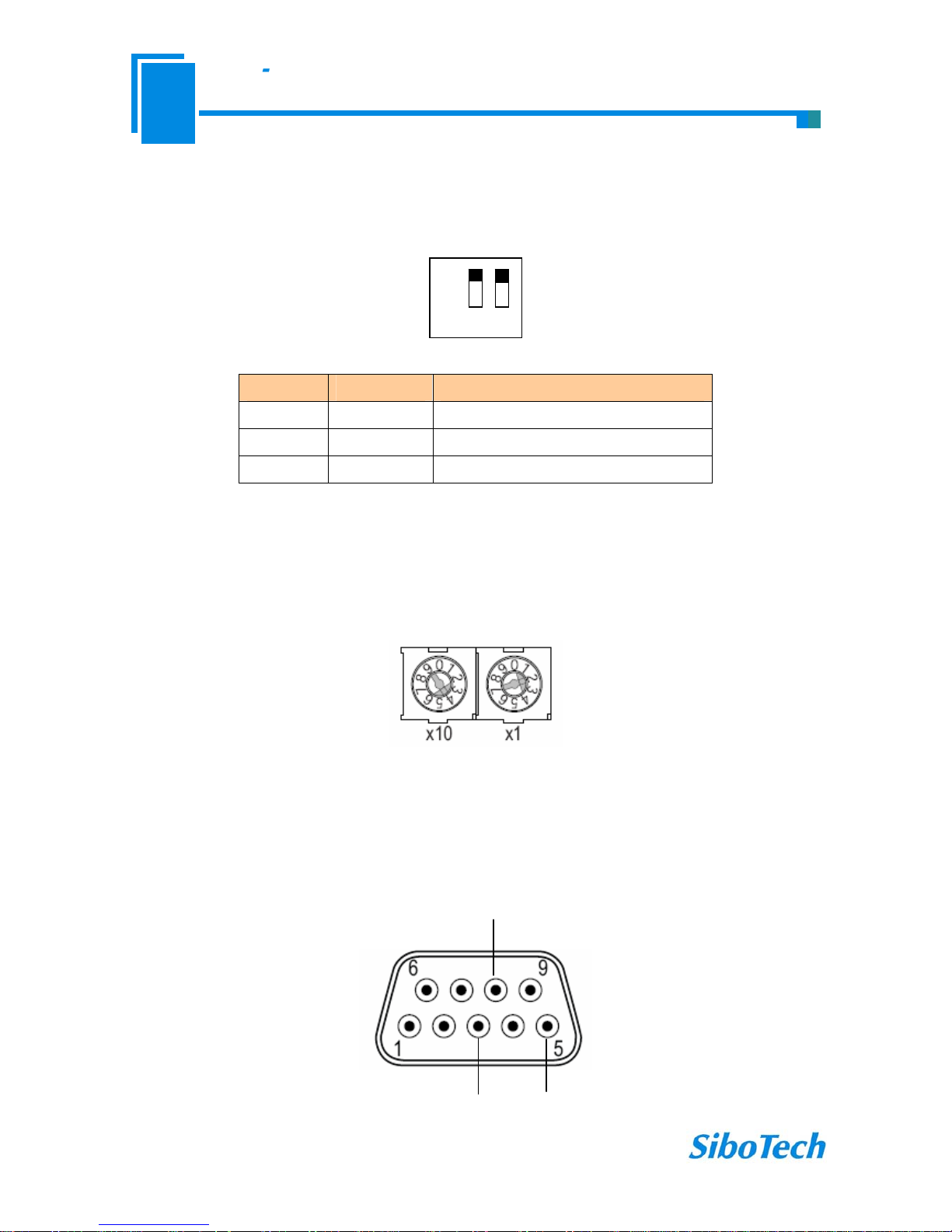
3.3 Rotary switch
The 2-code rotary switch in the left-side is used for setting the Profibus-DP address of the device.
In this example, the Profibus node address will be 42 (4x10) + (2x1).
3.4 Connectors
3.4.1 PROFIBUS-DPinterface
7
GND
PROFI-B
PROFI-A

User Manual
Profibus DP CANopen Gateway-/
PCO 150S
www.sibotech.net
DB9 pin Function
3 PROFI_B, Data positive
5 GND (optional)
8 PROFI_A, Data negative
3.4.2 CANopen connector
5-pin connector:
+24V
GND CAN-L
Shield
CAN-H
5 1
Open five-pin connector at the side of CAN:
Pin Connection
1 +24V (Optional)
2 CAN-H
3 Shield (Optional)
4 CAN-L
5 GND
Note 1: Connections of pin1 and pin 3 are optional, but connections of pin 2, pin 4 and pin5 are necessary;
Note 2: Pin 5, pin1 of CANopen interface interlinks V+, GND of power interface. You can only power on one of
the two interfaces.
8

User Manual
Profibus DP CANopen Gateway-/
PCO 150S
www.sibotech.net
3.5 Others
3.5.1Power interface
Note 1: V+, GND of power interface interlinks +24V, GND of CANopen interface. You can only power on one of
the two interfaces.
3.5.2 RS232 interface
Note 1: Connect RX, TX and GND of the interface with RX (pin 2), TX (pin 3) and GND (pin 5) of PC, and then
you can configurate PCO-150S through PC-123.
3.5.3 LED
In the configuration status, LED display CF, when downloading configuration, LED alternates display “C”
and “F”;
LED displays Profibus-DP slave address when gateway is in run status.
9

User Manual
Profibus DP CANopen Gateway-/
PCO 150S
www.sibotech.net
10
4 Use method
4.1 Quick start
1. This gateway has tow modes: configuration mode and run mode, you can select different mode through
DIP switch. Dial “mode” DIP switch to “on”, the gateway is in configuration mode, and dial “mode” DIP switch
to “off”, the gateway is in run mode;
2. Connect RS232 serial port to a PC and dial “mode” DIP switch to “on” then power on the module;
3. In the configuration mode, set CANopen baud rate, CANopen node ID, PDO and data mapping between
CANopen and Profibus-DP through PC-123. (See section 4.3 for details).
4. Dial "mode" DIP switch to "off" state, power on again and the module go into run status.
5. In run mode, users can debug data in input and output buffer through dialing “debug” DIP switch to “ON”
status. Users can see the data in debug interface of PC-123 through RS-232 interface;
6. Set the Profibus-DP slave address by rotary code switch.
4.2 Hardware connection
1. In accordance with the PROFIBUS port instructions, properly connected with DB9, recommended
standard Profibus-DP connector.
2. In accordance with the CAN port instructions, properly connected the 2, 4 pin at least.
3. Check all connections.
4. Dial configuration DIP switch to “RUN”, power on the module, and the module go into run status.
4.3 Software configuration
Users can connect PCO-150s to a PC through RS-232 port, and configurate parameters of gateway through
PC-123, including the gateway address at the side of CANopen, CAN baud rate, and input and output bytes.
See user manual of PC-123.
4.4 Run
4.4.1 Data exchange mode
Communication mode between CANopen and Profibus-DP is asynchronous mode, as shown below:

User Manual
Profibus DP CANopen Gateway-/
PCO 150S
www.sibotech.net
CANopen
PROFIBUS Gateway
Initiate Upload SDO
Request message (Data 1)
Response Upload SDO
Response message
Initiate Download SDO
Response Download SDO
……
Request message TPDO
RPDO
Response message (Data 2)
“Data 1” shows data transfer process from PROFIBUS to CAN; “Data 2” shows data transfer process from
CAN to PROFIBUS.
PCO-150S run in CANopen network independently, and transmit parameters read/write commands of
CANopen periodically according object dictionary, also transmit and receive PDO commands. If receive I/O
request from Profibus-DP, respond with the latest CANopen data to realize the matching of network speed. This is
asynchronous mode.
TPDO and RPDO apply producer/consumer mode, and often be used in occasion with high demand about
speed; Upload SDO and Download SDO apply client/server mode, the mode can guarantee safety of data, and
often be used in occasion with low demand about speed.
4.4.2 Profibus-DP Data Module
Data modules of gateway are shown as follow:
11

User Manual
Profibus DP CANopen Gateway-/
PCO 150S
www.sibotech.net
Numner Input Output
1 112 bytes 112 bytes
2 96 bytes 96 bytes
3 48 bytes 48 bytes
4 16 bytes 16 bytes
Input buffer 112/96/48/16
bytes
Profibus
PCO-150S
Output buffer 112/96/48/16
bytes
CANopen
Input and output buffer support the access of fast SDO command, the corresponding location of input and
output buffer in object dictionary is shown as follow:
Index Sub-index Description
0x2000 00 0~3 of 112 bytes (input buffer, four bytes, write)
0x2001 00 4~7 of 112 bytes (input buffer, four bytes, write)
0x2002 00 8~11 of 112 bytes (input buffer, four bytes, write)
0x2003 00 12~15 of 112 bytes (input buffer, four bytes, write)
0x2004 00 16~19 of 112 bytes (input buffer, four bytes, write)
0x2005 00 20~23 of 112 bytes (input buffer, four bytes, write)
0x2006 00 24~27 of 112 bytes (input buffer, four bytes, write)
0x2007 00 28~31 of 112 bytes (input buffer, four bytes, write)
0x2008 00 32~35 of 112 bytes (input buffer, four bytes, write)
0x2009 00 36~39 of 112 bytes (input buffer, four bytes, write)
0x200a 00 40~43 of 112 bytes (input buffer, four bytes, write)
0x200b 00 44~47 of 112 bytes (input buffer, four bytes, write)
0x200c 00 48~51 of 112 bytes (input buffer, four bytes, write)
0x200d 00 52~55 of 112 bytes (input buffer, four bytes, write)
0x200e 00 56~59of 112 bytes (input buffer, four bytes, write)
12

User Manual
Profibus DP CANopen Gateway-/
PCO 150S
www.sibotech.net
13
0x200f 00 60~63 of 112 bytes (input buffer, four bytes, write)
0x2010 00 64~67 of 112 bytes (input buffer, four bytes, write)
0x2011 00 68~71 of 112 bytes (input buffer, four bytes, write)
0x2012 00 72~75 of 112 bytes (input buffer, four bytes, write)
0x2013 00 76~79of 112 bytes (input buffer, four bytes, write)
0x2014 00 80~83 of 112 bytes (input buffer, four bytes, write)
0x2015 00 84~87 of 112 bytes (input buffer, four bytes, write)
0x2016 00 88~91 of 112 bytes (input buffer, four bytes, write)
0x2017 00 92~95 of 112 bytes (input buffer, four bytes, write)
0x2018 00 96~99 of 112 bytes (input buffer, four bytes, write)
0x2019 00 100~103 of 112 bytes (input buffer, four bytes, write)
0x201a 00 104~107 of 112 bytes (input buffer, four bytes, write)
0x201b 00 108~111 of 112 bytes (input buffer, four bytes, write)
0x3000 00 0~3 of 112 bytes (output buffer, four bytes, read)
0x3001 00 4~7 of 112 bytes (output buffer, four bytes, read)
0x3002 00 8~11 of 112 bytes (output buffer, four bytes, read)
0x3003 00 12~15 of 112 bytes (output buffer, four bytes, read)
0x3004 00 16~19 of 112 bytes (output buffer, four bytes, read)
0x3005 00 20~23 of 112 bytes (output buffer, four bytes, read)
0x3006 00 24~27 of 112 bytes (output buffer, four bytes, read)
0x3007 00 28~31 of 112 bytes (output buffer, four bytes, read)
0x3008 00 32~35 of 112 bytes (output buffer, four bytes, read)
0x3009 00 36~39 of 112 bytes (output buffer, four bytes, read)
0x300a 00 40~43 of 112 bytes (output buffer, four bytes, read)
0x300b 00 44~47 of 112 bytes (output buffer, four bytes, read)
0x300c 00 48~51 of 112 bytes (output buffer, four bytes, read)
0x300d 00 52~55 of 112 bytes (output buffer, four bytes, read)
0x300e 00 56~59 of 112 bytes (output buffer, four bytes, read)
0x300f 00 60~63 of 112 bytes (output buffer, four bytes, read)
0x3010 00 64~67of 112 bytes (output buffer, four bytes, read)
0x3011 00 68~71 of 112 bytes (output buffer, four bytes, read)
0x3012 00 72~75 of 112 bytes (output buffer, four bytes, read)
0x3013 00 76~79 of 112 bytes (output buffer, four bytes, read)
0x3014 00 80~83 of 112 bytes (output buffer, four bytes, read)

User Manual
Profibus DP CANopen Gateway-/
PCO 150S
www.sibotech.net
14
0x3015 00 84~87 of 112 bytes (output buffer, four bytes, read)
0x3016 00 88~91 of 112 bytes (output buffer, four bytes, read)
0x3017 00 92~95 of 112 bytes (output buffer, four bytes, read)
0x3018 00 96~99 of 112 bytes (output buffer, four bytes, read)
0x3019 00 100~103 of 112 bytes (output buffer, four bytes, read)
0x301a 00 104~107 of 112 bytes (output buffer, four bytes, read)
0x301b 00 108~111 of 112 bytes (output buffer, four bytes, read)
Request of SDO read command format:
COBID=0x600+nodeID data (8 bytes): 40 mm mm nn yy yy yy yy
“40” is fast read command, “mm mm” is index, “nn” is sub-index, “yy yy yy yy”is arbitrary value
Response of SDO read command format:
COBID=0x580+nodeID data (8 bytes): 43 mm mm nn dd dd dd dd
“43” is response of fast read command, “mm mm” is index, “nn” is sub-index, “dd dd dd dd” are data reading
from output buffer.
Example: Node ID is1, read data with index is 0x3000, and sub-index is 00 of output buffer through SDO read
command.
Request: COBID=0x601 data (8 bytes) 40 00 30 00 yy yy yy yy
Response: COBID=0x581 data (8 bytes) 43 00 30 00 01 02 03 04
“01 02 03 04” are data reading from output buffer.
Request of SDO write command format:
COBID=0x600+nodeID data (8 bytes) 23 mm mm nn dd dd dd dd
“23” is fast write command, “mm mm” is index, “nn” is sub-index, “dd dd dd dd” are data being written to input
buffer.
Response of SDO write command format:
COBID=0x580+nodeID data (bytes) 60 mm mm nn 00 00 00 00
“60” is fast write command, “mm mm” is index, “nn” is sub-index, “00 00 00 00” are default.
Example: Node ID is1, write data (01 02 03 04) to input buffer that index is 0x2000, and sub-index is 00 through
SDO write command.
Request: COBID=0x601 data (8 bytes) 23 00 20 00 01 02 03 04
Response: COBID=0x581 data (8 bytes) 60 00 20 00 00 00 00 00
“01 02 03 04” are data being written to input buffer.

User Manual
Profibus DP CANopen Gateway-/
PCO 150S
www.sibotech.net
5 Step7 Read and Write Gateway Data
Data module of PCO-150S that with total length as its consistent are shown as follow:
96Byte In, 96Byte Out
16 Byte In, 16 Byte Out
When use “96Byte In, 96Byte Out”, “16 Byte In, 16 Byte Out”, users must apply “SFC 14” read data and
“SFC 15” write data in Step 7 programming.
SFC14
SFC15
Data module of PCO-150S that with word as its consistent is shown as follow:
112 Byte In, 112 Byte Out
When use “112 Byte In, 112 Byte Out”, users can apply “MOVE” command read and write data in Step7
programming.
Data module of PCO-150S that with byte as its consistent is shown as follow:
48 Byte In, 48 Byte Out
When use “48 Byte In, 48 Byte Out”, users can apply “MOVE” command read and write data in Step7
programming.
15

User Manual
Profibus DP CANopen Gateway-/
PCO 150S
www.sibotech.net
6 Installation
6.1 Mechanical Dimension
Mechanical Dimension: 40mm (W)*125mm (H)*110mm (D)
6.2 Installation
35mm DIN rail installation
16

User Manual
Profibus DP CANopen Gateway-/
PCO 150S
www.sibotech.net
17
7 Failures and Suggestions
Number Description Suggestions
1 PBF(Profibus-DP Failure)always read Profibus-DP connection fail
2 PBF(Profibus-DP Failure)read out Profibus-DP connection OK
3 CAN-STATUS read light on in run status
CAN BUS OFF or error counter beyond alert
value;
Check CAN baudrate of gateway, and the
baudrate must be the same with other nodes
of CAN network
4 CAN-STATUS read light blinking in run status
Need a terminal resistance1on CAN network
or there is no connection between gateway
with CAN network
5 CAN-STATUS green light on but CAN transmit and
receive data fail in run status
Need a terminal resistance1on CAN network
or the node connected with gateway fail
6 CAN-STATUS read light blinking in run status
occasionally
There is error frame form CAN network, will
not affect communication
7 CAN-STATUS read light always blinking in run
status and no data in Profibus-DP
Check the baudrate of all the nodes on the
CAN network; If they are all the same, please
change a low baudrate and try again
8 ERR and RUN lights blinking fast Check Profibus-DP network
Note: Terminal resistance1
When communication distance is long or communication baudrate is high, users need a terminal resistance
(120Ω/2W) in both terminals of communication lines.

User Manual
Profibus DP CANopen Gateway-/
PCO 150S
www.sibotech.net
Appendix: Using STEP7 Set Profibus-DP
The following show how to use STEP7 to configure PCO-150S:
First of all, copy *. gsd file to the following path: Step7\S7data\gsd\
1. Open SIMATIC Manager ; Figure 1:
Figure 1
2. Click File->New, create a new project; Figure 2:
Figure 2
18

User Manual
Profibus DP CANopen Gateway-/
PCO 150S
www.sibotech.net
3. Insert->Station->SIMATIC 300 Station; Figure3:
Figure 3
4. Open S7 PLC hardware configuration: SIMATIC 300(1)->Hardware, double-click; Figure 4:
Figure 4
19
Table of contents
Other SiboTech Gateway manuals


Popular Gateway manuals by other brands


FACTBIRD
FACTBIRD DUO quick start guide

Garmin
Garmin GHP Reactor Steer-by-Wire Volvo quick start guide

ZyXEL Communications
ZyXEL Communications EMG6726-B10A quick start guide

DALCNET
DALCNET DGM02 Device manual

Accentronix
Accentronix CELLSWITCH 100 user manual

Netscape
Netscape NETSCAPE DIRECTORY SERVER 7.0 - GATEWAY... manual


