Sices D-PRO User manual

Technical Manual
D-PRO Protection relay
Filename: EAAM050902EN.docx
Rev. 02 Date: 22/10/2019
ID Document: EAAM0509
Product: D-PRO

ii D-PRO Protection relay Technical Manual
Revision
Date
Pages
Notes
00
05/04/2016
41
First revision
01
10/11/2016
45
Valid for the 01.05 revision of the controller.
Added alarm 579, 580, 581.
Added chapters: 4.5.1 and 4.6.10.
Modified chapters: 1.3.1, 3.1, 5, 6.2, 7.7-561, 7.7-579, 7.7-580, 7.7-
581.
02
22/10/2019
46
Valid for the 01.09 revision of the controller.
Modified chapters: 4.7.7, 4.7.8

D-PRO Protection relay Technical Manual iii
SUMMARY
1. Introduction..............................................................................................................1
1.1 References...........................................................................................................1
1.2 Safety information.................................................................................................1
1.3 General info..........................................................................................................2
1.3.1 Protections (ANSI/IEEE codes)......................................................................2
1.4 Prerequisites.........................................................................................................2
1.5 Switch SW1..........................................................................................................3
1.5.1 Notes on the configuration of the device parameters .....................................3
1.6 Definitions.............................................................................................................3
1.6.1 Faults..............................................................................................................3
1.6.2 Acronyms .......................................................................................................4
1.7 Conventions..........................................................................................................4
1.8 Firmware revisions................................................................................................4
2. Views of the device..................................................................................................5
3. Installation................................................................................................................6
3.1 Mounting...............................................................................................................6
3.2 Wiring ...................................................................................................................6
4. Connections.............................................................................................................7
4.1 Device supply (JB)................................................................................................7
4.2 LEDs.....................................................................................................................7
4.3 Digital inputs (JM).................................................................................................9
4.3.1 Digital inputs configuration .............................................................................9
4.3.2 Virtual digital inputs ......................................................................................10
4.4 Digital outputs (JL/JI)..........................................................................................11
4.4.1 Digital outputs configuration.........................................................................11
4.4.2 AND/OR logics.............................................................................................13
4.5 Virtual analogue inputs.......................................................................................14
4.5.1 Configuration of virtual analogue inputs.......................................................15
4.6 Measurement inputs...........................................................................................17
4.6.1 Measuring of the genset voltages.................................................................17
4.6.2 Measuring of the Genset neutral..................................................................17
4.6.3 Measuring of the homopolar voltage ............................................................17
4.6.4 Measuring of the currents.............................................................................17
4.6.5 Measuring of the current A...........................................................................18
4.6.6 Measuring of the current B...........................................................................18
4.6.7 Measuring of the differential current.............................................................18
4.6.8 Measuring of the load average current.........................................................18
4.6.9 Measuring of the auxiliary current ................................................................19
4.6.10 Measuring of the differential current used for restricted earth fault .........20
4.6.11 Measuring of the sequence current (0 / + / -)..........................................20
4.7 Communication...................................................................................................21
4.7.1 RS232 Serial Port 1 (JP)..............................................................................21
4.7.2 RS485 Serial Port 2 (JO)..............................................................................22
4.7.3 USB Port (JA)...............................................................................................23
4.7.4 Ethernet (JQ)................................................................................................24
4.8 CAN-BUS Connection ........................................................................................25
4.8.1 CAN-BUS Connection (JN) ..........................................................................25

iv D-PRO Protection relay Technical Manual
5. “Si.Mo.Ne” System ................................................................................................26
6. Operating sequence ..............................................................................................27
6.1 Operating mode..................................................................................................27
6.2 Inhibition to the protection intervention...............................................................27
7. Faults......................................................................................................................29
7.1 Silence the horn..................................................................................................29
7.2 Identify the anomaly............................................................................................30
7.3 Cancel the anomaly............................................................................................30
7.4 Signals................................................................................................................30
7.5 Protections Override...........................................................................................30
7.6 Faults connected to digital inputs .......................................................................31
7.7 Faults list ............................................................................................................31
37 –Low battery voltage threshold (from measuring)...................................................31
38 –High battery voltage threshold (from measuring)..................................................31
561 –Minimum voltage (27).........................................................................................32
562 –Minimum voltage (27T).......................................................................................32
563 –Maximum reactive power (32P)..........................................................................33
564 –Maximum reactive power (32Q)..........................................................................34
565 –Negative sequence (46) .....................................................................................34
566 –Wrong phases sequence (47).............................................................................34
567 –Short circuit (50).................................................................................................35
568 –Short circuit on neutral (50N)..............................................................................35
569 –Short circuit with restrained overcurrent (50V)....................................................35
570 –Maximum current (51) ........................................................................................36
571 –Maximum current on neutral (51N).....................................................................36
572 –Maximum current with restrained overcurrent (51V)...........................................36
573 –Maximum voltage (59)........................................................................................39
574 –Maximum homopolar voltage (59N)....................................................................40
575 –Minimum frequency (81U) ..................................................................................40
576 –Maximum frequency (81O).................................................................................40
577 –Maximum genset differential current (87G) ........................................................41
578 –Maximum transformer differential current (87T)..................................................41
579 –Power reverse (32RP)........................................................................................43
580 –Reactive power reverse / Loss of excitation (32RQ/40)......................................43
581 –Restricted earth fault / Maximum differential current (64)...................................44
252 –CAN-BUS 2 Expansion modules missing (EXBUS)............................................44
254 –Input doubled on CAN-BUS 2 (EXBUS) .............................................................44
701...742 - Generic faults related to the digital inputs...................................................44
301...328 - Generic faults related to the analogue inputs .............................................44
8. Other functions......................................................................................................45
8.1 Parameters alternative configurations ................................................................45
8.2 Clock...................................................................................................................45

D-PRO Protection relay Technical Manual v
INDEX
A
AVF.4001 13
AVF.4002 13
AVF.4003 13
AVF.4004 13
AVF.4005 13
AVF.4006 13
AVF.4007 13
AVF.4008 13
AVF.4009 13
AVF.4010 13
AVF.4017 13
AVF.4018 13
AVF.4019 13
AVF.4023 13
AVF.4024 13
AVF.4025 13
AVF.4029 13
AVF.4030 13
AVF.4033 13
AVF.4034 14
AVF.4035 14
AVF.4036 14
AVF.4037 14
AVF.4038 14
AVF.4041 14
AVF.4047 14
AVF.4051 14
AVF.4052 14
AVF.4053 14
AVF.4054 14
AVF.4058 14
AVF.4059 14
AVF.4105 14
D
DIF.2001 9; 27
DIF.2063 9; 28
DIF.2151 9; 41
DIF.2152 9; 41
DIF.2153 9; 41
DIF.2154 9; 41
DIF.2704 9; 16
DIF.2705 9
DIF.2711 9; 24
DIF.2712 9; 24
DIF.2713 9; 24
DIF.2714 9; 24
DIF.2715 9; 24
DIF.2716 9; 24
DIF.2717 9; 24
DIF.2718 9; 24
DIF.3001 9
DIF.3201 9
DIF.3202 9
DIF.3203 9
DIF.3204 9
DIF.3205 9
DIF.3206 9
DIF.4001 9; 28
DIF.4004 9; 28
DOF.0000 9; 10; 11
DOF.0103 11; 12; 27
DOF.1001 11
DOF.1002 11
DOF.1003 11
DOF.2001 11
DOF.2002 11
DOF.2003 11
DOF.2004 11
DOF.3151 11; 27
DOF.3152 11; 27
DOF.4001 11; 27
DOF.4004 27
P
P.0101 14; 29; 31; 32; 33; 36; 41
P.0102 29; 31; 32; 33; 36; 41
P.0103 41
P.0104 41
P.0105 37
P.0106 30; 31
P.0107 31; 32
P.0110 15
P.0111 15
P.0112 15
P.0115 16
P.0116 16
P.0117 15
P.0119 16; 17
P.0120 17
P.0121 17
P.0122 17
P.0125 17
P.0126 17
P.0127 17
P.0129 15
P.0130 29
P.0151 15
P.0201 9; 24; 25
P.0202 9; 24; 25
P.0203 9; 24; 25
P.0204 9; 24; 25
P.0205 9; 24; 25
P.0206 9; 24; 25
P.0207 9; 24; 25
P.0208 9; 24; 25
P.0221 11
P.0222 11

vi D-PRO Protection relay Technical Manual
P.0223 11
P.0224 11
P.0305 37
P.0306 37
P.0307 37
P.0308 37
P.0321 29
P.0322 29
P.0323 36
P.0324 32; 36
P.0325 29
P.0326 29; 31
P.0327 29
P.0328 31; 32
P.0329 31; 32
P.0330 37
P.0331 37
P.0351 33
P.0352 33; 34; 35; 36
P.0353 33; 34; 35; 36
P.0354 33
P.0355 33; 34
P.0356 33; 34
P.0357 33; 34
P.0358 33; 34
P.0359 33; 34
P.0360 32
P.0361 32
P.0362 32
P.0363 32
P.0364 32
P.0365 32
P.0366 31
P.0367 31
P.0370 38
P.0371 38; 39; 40
P.0372 38; 39; 40
P.0373 38; 40
P.0374 38; 40
P.0375 38; 40
P.0376 38; 40
P.0380 30; 31
P.0381 30; 31
P.0382 31
P.0383 31
P.0391 28
P.0392 28
P.0393 28
P.0394 28
P.0452 18
P.0453 18
P.0454 18
P.0456 21
P.0470 18
P.0472 19
P.0473 19
P.0474 19
P.0475 19
P.0478 20
P.0479 20
P.0491 26
P.0500 21
P.0501 21
P.0502 21
P.0503 21
P.0504 21
P.0505 21
P.0508 21; 22
P.0509 21; 22
P.0510 21
P.0511 21
P.0513 21
P.0514 21
P.0530 23
P.0531 23
P.0532 23
P.0533 23
P.0534 23
P.0535 23
P.0536 23
P.0537 23
P.0539 23
P.0542 23
P.0701 40
P.2000 8
P.2001 8; 28
P.2002 8; 28
P.2003 8; 28
P.3001 10
P.3002 10
P.3003 10
P.3004 10
P.3005 10
P.3006 10
P.3007 10
P.3008 10
P.3009 10
P.3010 10
P.3011 10
P.3012 10

D-PRO Protection relay Technical Manual 1
1.
1.1
[1] SICES EAAM0495xx - D-PRO parameter tables.
[2] SICES EAAS0496xx –D-PRO Modbus registers
[3] SICES EAAS0341xx –Serial Communication.
[4] BOSCH CAN Specification –Version 2.0 –1991, Robert Bosch Gmbh
[5] CAN open –Cabling and Connector Pin Assignment –CIA Draft Recommendation DR-
303-1
[6] SICES EAAP0457xx –USB driver Installation Guide
[7] SICES EAAM046200IT –Ethernet TCP/IP –Rapid Installation Guide.
[8] SICES EAAM00458xx –BoardPrg 3.xx Software Manual
[9] EAAM0410xx –SI.MO.NE User Manual.
1.2
Many accidents are caused by poor knowledge and the non-observance of safety regulations,
which must be observed when operating and/or servicing the machine.
Before using or servicing the machine, you should read, understand and observe the
precautions and warnings in this manual, in order to prevent accidents.
In order to identify the safety messages included in this manual, see the words listed below.
WARNING! This indication is used in the safety messages of the manual when
there are possible danger situations that may cause injuries or death if the danger is
not avoided.
This safety messages describe the normal precautions needed to avoid danger.
Ignoring this instructions may cause serious damages to things and/or people.
WARNING! This indication is used in the safety messages for dangers that, if not
avoided, may cause injuries, damages or malfunctioning.
The message can be also used only for few dangers that may cause damages to things
and/or people.
INFORMATION! This term indicates that the message provides useful information
forperforming the current operation, or for explanations or clarifications of procedures.

2 D-PRO Protection relay Technical Manual
1.3
D-PRO is a protection relay for the genset. It includes all the necessary functions to acquire
the measurements of the plant and to activate one or more outputs in order to keep the plant
safe in case of irregular values acknowledged. The system is not equipped by a multifunctional
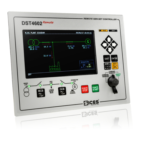
display, but it requires the connection to the DST4602 controller for a complete use with the
visualization of the faults and the measurements of frequency, voltage, current and power of
the plant. In case of “stand-alone” use (without connection to the DST4602 controller), the D-
PRO protection relay carries out the same basic functions, but the information are displayed
through LEDs.
1.3.1
The following table shows the protections implemented:
Protection
Description
1
27
Minimum generator's voltage
2
27T
Minimum generator's time-dependent
3
32P
Maximum active power
4
32Q
Maximum reactive power
5
46
Negative sequence
6
47
Wrong phases sequence
7
50
Short circuit
8
50N
Neutral short circuit
9
50V
Short circuit with voltage-restrained
10
51
Maximum current
11
51N
Maximum neutral current
12
51V
Maximum current with voltage-restrained
13
59
Maximum generator's voltage
14
59N - 59V0
Maximum residual voltage (homopolar voltage)
15
81O
Maximum generator's frequency
16
81U
Minimum generator's frequency
17
87G
Genset earthing differential protection
18
32RP
Active power reverse
19
32RQ / 40
Reactive power reverse / Loss of excitation
20
64
Restricted earth fault / Maximum differential current
1.4
For the appropriate use of this manual it is required knowledge of the use and of the
installation of generator groups.
WARNING!!!
Every operation must be carried out by skilled personnel. There are dangerous voltages on
the terminals of the device; before carrying out any operation on them, ensure you have
opened the mains and genset circuit breakers or removed the related fuses.

D-PRO Protection relay Technical Manual 3
Do not remove or modify any connection during the genset operation.
Do not disconnect the current transformers terminals (C.T.) for any reason.
Wrong interventions on connections can cause the disconnection of the loads from the mains
or the genset.
Please read this manual carefully before using the device.
The device uses a large number of configurable parameters; therefore, it is impossible
to describe all their possible combinations and effects.
In this document, there isn’t a detailed description of all programming parameters: to this
purpose, see [1]. These documents have to be considered as part of this manual.
The devices are supplied with a generic “default” configuration; it is the installer’s
responsibility to adjust the operating parameters to the specific application.
SICES srl carries out a great effort to improve and update its products; therefore, they are
subject to both hardware and software modifications without notice. Some of the features
described in this manual may differ from those present in your device.
1.5
IMPORTANT Both SW1 switches must stay on position OFF.
The SW1 switches allow a reserved access to special functions that usually are not included
in the normal operation of the device.
If the device is supplied with one of the two switches on ON, it does not turn on. In order
to bring the device back to the normal operation, you need to disconnect it, position the
switches on OFF and connect it again.
If the device does not turn on when supplied, check the position of the switch first.
1.5.1
The parameters and the functions can be configured or adjusted exclusively by the PC
program SICES Board Programmer3 [8] (hereinafter called “BoardPrg3”) installed on the
CD supplied together with the device and downloadable for free, after registration, on SICES
Srl websites. www.sices.eu e www.sicesbrasil.com.br.
It considerably simplifies the configuration of the device and allows the file saving of the device
configuration and its following use on other similar devices too.
The program also allows the configuration, saving or loading of the characteristic curves of
non standard analogue sensors with resistive or live output.
BoardPrg3 [8] can be used on all SICES devices; the connection to the PC can be direct via
serial RS232 or USB, or by remote via modem, serial RS845 or Ethernet. For the use of the
program, refer to the proper manual.
1.6
1.6.1
D-PRO is able to report and manage all the faulty conditions occurring during the operation of
the system. The faults are classified in two categories, according to their severity and based
on the actions D-PRO performs to manage them:

4 D-PRO Protection relay Technical Manual
•Warning. This term is used to indicate an anomaly that, under the current
circumstances, doesn’t compromise the operation of the genset: the operator should
take note of it anyway, because sooner or later it could worsen in a more serious
anomaly.
•Alarm. This term is used to indicate an anomaly that requires the stop of genset.
There are immediate risks for the genset, therefore it needs to be stopped
immediately.
1.6.2
AIF It identifies a function for the configuration of the analogue inputs (“Analogue
Input Function”). The number that follows the caption “AIF” is the code to set in
the parameter that configures the function of the desired analogue input.
AOF It identifies a function for the configuration of the analogue outputs (“Analogue
Output Function”). The number that follows the wording “AOF.” is the code to
set in the parameter that configures the function of the desired analogue output.
AVF It identifies a function for the configuration of virtual analogue inputs (“Analogue
Virtual Function”). The number that follows the wording “AVF.” is the code to
set in the parameter that configures the function of the desired analogue input.
DIF It identifies a function for the configuration of digital inputs (“Digital Input
Function”). The number that follows the caption “DIF” is the code to set in the
parameter that configures the function of the desired digital input.
DOF It identifies a function for the configuration with the digital outputs (”Digital
Output Function”). The number that follows the caption “DOF” is the code to set
in the parameter that configures the function of the desired digital output.
EVT It identifies an event in the history log. The number that follows the caption
“EVT” is the numeric code of the event.
ST It identifies a controller status (”Status”). The code the follows the caption “ST.”
indicates a status of a measurement or a condition of the device or of one of its
functions.
AL It identifies an alarm (”Alarm”). The number that follows the caption “AL.”
indicates the alarm numeric code.
1.7
In this manual, the modifications, with respect to the previous version, are signalled by a
vertical bar on the right of the paragraphs. The modifications on the fields of a table are
highlighted with a grey background.
1.8
The software revisions will be described in different part of the manual. These revisions are
referred with the SICES code assigned to it (which is reported on a label on the controller rear
side). The code format is: EB0250247XXYY, where “XX” is the major version number and “YY”
is the minor version number. Thus, the code EB02502470100 refers to the controller software
release "1.00".
INFORMATION! In the codes above, the two letters marked with YY can be replaced
by a number indicating the version. The two final letters XX can be replaced by a
progressive number indicating the product revision or option.

D-PRO Protection relay Technical Manual 5
2.

6 D-PRO Protection relay Technical Manual
3.
3.1
The device has to be mounted permanently on a panel. The rear panel of the device must be
accessible only by authorized personnel for maintenance operations. Use four screws with
metric thread 4 MA and brackets supplied. The drilling wheelbase is 266x130mm.
3.2
SICES s.r.l. cannot be considered responsible for damages to things or persons for the
failure to respect the installations and connections indications of the device.

D-PRO Protection relay Technical Manual 7
4.
4.1
WARNING! In order to respect the safety rules, you must guarantee an electrical
insulation not lower than the one of a safety transformer compliant to the IEC61558-2-6
or equal regulation.
The JD connector is the supply connector: connect a continuous power supply (usually the
engine starter battery) to the 1-GND terminal (negative) and to the 2-+BATT terminal
(positive).
The negative terminal 1-GND is the reference and the common return of the digital inputs,
outputs and current and voltage measurements. It must be connected to the protective
earth. The systems that require insulation between the battery negative and the earthing
protection can be used but can generate operating problems and may require particular care,
as the use of insulation current transformers for the voltage measurements of Mains and
Genset.
Although the device is protected by a built-in self-resetting fuse, it is recommended that you
use a fuse for the protection of the positive line 2-+BATT. The device automatically
acknowledges when it is powered if the genset battery nominal voltage is 12 or 24V for
managing the related logics and alarms.
NOTE: during the installation, connect the positive voltage only after all fuses available
in the panel are all opened.
4.2
The controller uses eight LEDs for the user’s visualization and four red LEDs associated to
the status of the four relay outputs. The LEDs are only on the controller, but they are not
associated to any output (static or relay output) and they have the following default function.
Led off
LED steady ON
LED flashing
LED
Colour
Signalling
Function
ON
Green
Controller status
Controller working
Controller in alarm
Controller in alarm

8 D-PRO Protection relay Technical Manual
LED
Colour
Signalling
Function
AUX LINK
Green
Serial
communication
status
It indicates that a communication on one of the serial
interfaces.
It indicates that no communication on the serial interfaces.
CANBUS
Green
INTERFACE
DST4602 Status
It signals that the CAN-BUS interface is active and in
ERROR-ACTIVE mode.
Flashing at 25% it indicates a communication fault: the
port is in ERROR-PASSIVE mode.
Flashing at 75% it indicates a communication fault: the
port is in BUS-OFF mode.
It signals that the CAN-BUS is disabled.
LED 1
Green
-
Not used.
LED 2
Green
-
Not used.
ENABLE
Green
Protection
enabled.
At least one protection is enabled.
No protection is enabled (that is the protection controller is
disabled).
ACTIVE
Yellow
Protection
activated.
At least one protection is enabled and exceeded the
threshold.
No protection is activated.
TRIP
Red
Triggered
protection
At least one protection has triggered (TRIP).
In order to switch off the LED, you need to reset the
protection with the reset input or by positioning the key
selector on DST4602 on OFF/RESET.
No protection has triggered.
The status of disabled protection (LED ENABLE off) is acknowledged by OR conditions:
- GCB status input opened (only if configured).
- All the configured inputs of protections disabling are active.
The status of enabled protection (LED ENABLE on) is signalled when at least one protection
is enabled (no input or disabling parameter is active) and lower than the protection threshold.
The status of activated protection (LED ACTIVE steady on) is signalled when at least one
protection is enabled (no input or disabling parameter is active) and exceeded the protection
threshold. The LED refers to the measurements by activating when it exceeds the threshold
and by deactivating when it is lower than the threshold (even in case the protection triggers).

D-PRO Protection relay Technical Manual 9
4.3
The controller is already equipped with 8 digital inputs that activate by connecting them to
GND. When it is left floating, the input brings itself to +Vbatt. Avoid situations where
intermediate or undefined voltage levels can occur.
In addition to the 8 physical digital inputs, the controller also manages 16 virtual digital inputs.
They are managed by the controller exactly as they were physical inputs (without limitations).
The virtual inputs status is not acquired by the hardware, but it is determined by software. In
fact, every digital input can be associated to an AND/OR logic that determines its status (see
par. 4.4.2).
4.3.1
By default, all digital inputs are “active” only when the related terminal is connected to the
negative of the supply voltage of the controller; they are considered “not active” when the
related terminal is not connected to anything. The logic status of the input can be inverted
with respect of the physical status by selecting the box “Reverse polarity” in the input
configuration page on BoardPrg3. The box is only visible if the function selected is other
than DIF.0000 –“Not used”.
It is also possible to invert the logic status (always individually for each input), by operating
directly on the controller by using the parameters P.2000 (for the input 1..8 present on the
controller).
Said parameters have a bit for each output:
•A bit set to zero means that the related input is “active” when it is connected to the
negative supply of the controller.
•A bit set to one means that the related input is considered “active” when the terminal
is not connected to anything (it will become “not active” when the terminal is connected
to the supply negative of the controller).
By default, all bits are set to zero.
Each input (both physical and virtual) has three parameters associated:
•One parameter that configures its function (P.2001 for input 1).
•One parameter that configures the delay time (P.2002 for the input 1).
•One parameter that configures a message to show on the display (P.2003 for the input
1).
See documents [1] for the parameters list.
The management of the physical and virtual inputs is the same.
The parameters that configure the delay and the message for an input are used by the
controller only for certain features of the inputs. The following table highlights when they are
used.
NOTE: in BoardPrg3, the boxes for the delay and for the message are always showed,
even if they are not used by the controller.
The identification of the inputs functions that start with 3xxx concern operating statuses, while
the ones that start 4xxx activate alarms (warning or alarms).

10 D-PRO Protection relay Technical Manual
Input
Function
Name
Delay
Description
DIF.0000
Not used.
Input not used.
DIF.2001
Reset command of the alarms,
When the input becomes “active”, the controller carries out a complete reset
of all anomalies.
DIF.2063
Protections override
When the input is “active”, all the protections, which normally act as alarms,
become mere warnings.
DIF.2151
Select configuration 1.
When the input becomes “active”, the configuration parameters of the
alternative 1 are copied in the working parameters.
DIF.2152
Select configuration 2.
When the input becomes “active”, the configuration parameters of the
alternative 2 are copied in the working parameters.
DIF.2153
Select configuration 3.
When the input becomes “active”, the configuration parameters of the
alternative 3 are copied in the working parameters.
DIF.2154
Select configuration 4.
When the input becomes “active”, the configuration parameters of the
alternative 4 are copied in the working parameters.
DIF.2704
Disable the protections on the 4th
current.
When this input is “active”, the auxiliary current protection (normally used
for the differential protection) is disabled.
DIF.2705
Disable the protections on the
analogue measures.
When this input is “active”, the thresholds set on analogue measurements
with bit 13 ON in the third configuration parameter do not cause the
intervention of the related protections.
DIF.2711
Protections disabling - level 1
Disable the protections configured in the parameter P.0201.
DIF.2712
Protections disabling - level 2
Disable the protections configured in the parameter P.0202.
DIF.2713
Protections disabling - level 3
Disable the protections configured in the parameter P.0203.
DIF.2714
Protections disabling - level 4
Disable the protections configured in the parameter P.0204.
DIF.2715
Protections disabling - level 5
Disable the protections configured in the parameter P.0205.
DIF.2716
Protections disabling - level 6
Disable the protections configured in the parameter P.0206.
DIF.2717
Protections disabling - level 7
Disable the protections configured in the parameter P.0207.
DIF.2718
Protections disabling - level 8
Disable the protections configured in the parameter P.0208.
DIF.3001
GCB circuit breaker status.
Yes
An input with such configuration is used to communicate the plant GCB
(Genset) circuit breaker status to the protection relay.
DIF.3201
Generic status (page 1).
If this input is “active”, the controller shows the text configured by the
parameters associated to the input.
DIF.3202
Important generic status (page 1).
If this input is “active”, the controller shows the text configured by the
parameters associated to the input.
DIF.3203
Generic status (page 2).
If this input is “active”, the controller shows the text configured by the
parameters associated to the input.
DIF.3204
Important generic status (page 2).
If this input is “active”, the controller shows the text configured by the
parameters associated to the input.
DIF.3205
Generic status (page 3).
If this input is “active”, the controller shows the text configured by the
parameters associated to the input.
DIF.3206
Important generic status (page 3).
If this input is “active”, the controller shows the text configured by the
parameters associated to the input.
DIF.4001
Generic warning.
Yes
If the input is “active”, a warning is activated: the message shown is the one
set in the parameters associated to the input.
DIF.4004
Generic shut-down.
Yes
When the input is “active”, a shut-down is activated: the text displayed is the
one set in the parameters associated to the input.
4.3.2
In addition to the 8 digital physical inputs, the controller also operates 16 virtual digital inputs.
The same are operated by the controller just as if they were physical inputs (with no limitation),
but the status of the virtual inputs is not acquired from the hardware, but it is determined
through the software. In fact, every digital input can have an AND/OR logic associated, which
determines its status (see par.4.4.2).
Each virtual digital input has three parameters associated; see below for example the ones
related to virtual digital input 1; for the parameters of the other inputs see document [8] or the
I/O configuration page of the BoardPrg3.
We have:
•One parameter which configures its function (P.2151 for the virtual digital input 1).
•One parameter which configures any message (P.2152 for the virtual digital input 1).
•One parameter which configures the (P.2153 for the virtual digital input 1).

D-PRO Protection relay Technical Manual 11
4.4
The D-PRO protection relay is equipped with four relay outputs with dry contact in exchange,
max. 10A/250Vac all fully adjustable.
Terminal
Type
Function
Output
Function
configured
JL - 1
Relay,
10A
250Vac
N.O.
Output 01
DOF.0000 - Not
used.
JL - 2
N.C.
JL - 3
COM.
JL - 4
Relay,
10A
250Vac
N.O.
Output 02
DOF.0000 - Not
used.
JL - 5
N.C.
JL - 6
COM.
Terminal
Type
Function
Output
Function
configured
JI - 1
Relay,
10A
250Vac
N.O.
Output 03
DOF.0000 - Not
used.
JI - 2
N.C.
JI - 3
COM.
JI - 4
Relay,
10A
250Vac
N.O.
Output 04
DOF.0000 - Not
used.
JI - 5
N.C.
JI - 6
COM.
4.4.1
All controller digital outputs (JL and JI) are fully adjustable individually. Each output is
associated to the following parameters:
•A parameter that configures the function (P.3001 for the input 1):
•A parameter that configures the output activation mode (P.3002 for the input 1):
o0-Normal: the output manages the command guaranteeing a minimum activation
time (if the time set is different from zero).
o1-Maintained: the output stays active up to the reset command.
o2-Impulsive: the output activates for the time set and stays deactivated until a
new command change.
•A parameter that configures the impulse activation or duration minimum time (P.3003 for
the input 1). By setting it to zero, the output command stays stable on ON/OFF.
Parameter
Output
Description
P.3001
Output 1 (JL-1)
Output 01 function.
P.3002
Output 01 type (activation mode).

12 D-PRO Protection relay Technical Manual
P.3003
Output 01 delay.
P.3004
Output 2 (JL_3)
Output 02 function.
P.3005
Output 02 type (activation mode).
P.3006
Output 02 delay.
P.3007
Output 3 (JI_4)
Output 03 function.
P.3008
Output 03 type (activation mode).
P.3009
Output 03 delay.
P.3010
Output 4 (JI_1)
Output 04 function.
P.3011
Output 04 type (activation mode).
P.3012
Output 04 delay.
By default, all the outputs activate when required by the related function. Using BoardPrg3, it
is possible to invert the activation by simply selecting the box “Inverted polarity” on the top of
the configuration page of each output.
•A zero-bit means that the output is normally in standby and starts operating when required
by the related function.
•A one-bit means that the output is normally operating and goes in standby when required
by the related function.
The map of the outputs present on the controller is:
BIT
Value
Output
0
1
Output 1 (JL-1)
1
2
Output 2 (JL_3)
2
4
Output 3 (JI_4)
3
8
Output 4 (JI_1)
By default, all bits are set to zero.
The status of the digital outputs is displayed by the proper LEDs (OUT1, OUT2, OUT3, OUT4)
mounted on the controller.
The digital outputs can be used directly as command for controller external devices or as
signalization of particular operating conditions. Below the functions adjustable on the digital
outputs:
Code
Description
Delay
+ mode
Note
DOF.0000
Not used
DOF.0103
AND/OR logics.
The output status results from the combination of the
AND/OR logics.
DOF.1001
Protection enabling (ENABLE)
YES
It activates the output when at least one protection is
enabled (the parameters are configured correctly and
no protections disabling input is active)
DOF.1002
Protection activation (ACTIVE)
YES
It activates the output when at least one protection is
started (the threshold has been exceeded but the
time configured has not passed)
DOF.1003
Protection intervention (TRIP)
YES
It activates the output when at least one protection
has triggered (the threshold has been exceeded for
the time configured) The reset depends on the
activation of the alarms reset input.
DOF.2001
Protections configuration - level 1
YES
It activates the output if one of the protections
configured in the parameter P.0221triggered.
DOF.2002
Protections configuration - level 2
YES
It activates the output if one of the protections
configured in the parameter P.0222triggered.
DOF.2003
Protections configuration - level 3
YES
It activates the output if one of the protections
configured in the parameter P.0223triggered.
DOF.2004
Protections configuration - level 4
YES
It activates the output if one of the protections
configured in the parameter P.0224triggered.
DOF. 3031
Frequency within tolerance
YES
It activates when the frequency parameters are within
normal operation. It activates if there is at least one
frequency within tolerance

D-PRO Protection relay Technical Manual 13
DOF.3151
Faults reset
YES
It activates when the controller goes to RESET mode
DOF.3152
External horn
YES
It activates together with an internal horn.
DOF.4001
Warnings
YES
It activates in case of warnings
DOF.4005
Alarms (deactivations and unloads)
YES
It activates in case of alarms (deactivations and shut-
downs)
4.4.2
AND/OR logics are simply a list of boolean values (true/false, on/off, 1/0), which can be
configured by the operator (programming), which the controller evaluates and whose result
can be assigned to a digital output or to a virtual digital input (see par. 4.4.1). For using the
AND/OR logics with a digital output, use the DOF.0103function.
NOTE: the configuration of the AND/OR logics must be carried out by means of a PC
with the software BoardPrg3.
First, the operator must decide if the list of conditions have to be evaluated as AND (all must
be verified) or OR (at least one condition must be verified). It’s not possible to have mixed
AND/OR logics (you can do it using virtual digital inputs, see below).
You can add up to 30 conditions. Each condition can be denied individually: for example, in
the figure above the controller will verify that the digital input 3 and the digital output 8 are both
not active. The following conditions can be added:
•DI_XXX: logic statuses of all digital inputs (physical and virtual).
•DO_XXX: logic statuses of all digital outputs.
•AL_XXX: presence of warning/alarms.
•ST_XXX: internal statuses of the controller.
•AT_XXX: statuses concerning the thresholds on analogue measures.
The following table shows the list of the internal statuses available for the AND/OR logics.

14 D-PRO Protection relay Technical Manual
Status
Description
ST_008
Warnings cumulative
ST_011
Locks cumulative
ST_012
Unacknowledged warnings cumulative
ST_015
Unacknowledged locks cumulative
Using the virtual digital inputs, it is possible to create mixed AND/OR logics (that is composed
by AND and OR together). Let’s suppose we would like to activate the digital output #1 when
the digital inputs #1 and #2 are both active, or if the digital input #3 is active.
First of all we need to associate to the virtual digital input #1 (for example) an AND/OR logic
configured as AND, which verifies that the first two digital inputs are both active. Then we need
to associate to the digital output #1 an AND/OR logic configured as OR, which verifies that the
virtual digital input #1 or the digital input #3 is active. Basically, we use the virtual digital input
#1 as “support” for the AND condition. In this case, it is not necessary to associate any function
to the virtual digital input.
4.5
The controller manages 8 virtual analogue inputs. They are managed by the controller exactly
as they were physical inputs (without limitations). The virtual inputs status is not acquired by
the hardware, but it is determined by software. By means of the parameter “function” of each
virtual analogue input, indeed, it is possible to “copy” one of the internal measurement
available on the controller in the analogue input:
•AVF.4001 - Frequency
•AVF.4002 - L1-N Generator voltage
•AVF.4003 - L2-N Generator voltage
•AVF.4004 - L3-N Generator voltage
•AVF.4005 - L-N Average Generator voltage
•AVF.4006 - L1-L2 Generator voltage
•AVF.4007 - L2-L3 Generator voltage
•AVF.4008 - L3-L1 Generator voltage
•AVF.4009 - L-L Average Generator voltage
•AVF.4010 - Homopolar voltage (59N)
•AVF.4017 - L1 Phase voltage - Upper part (A)
•AVF.4018 - L2 Phase voltage - Upper part (A)
•AVF.4019 - L3 Phase voltage - Upper part (A)
•AVF.4023 - L1 Phase voltage - Lower part (B)
•AVF.4024 - L2 Phase voltage - Lower part (B)
•AVF.4025 - L3 Phase voltage - Lower part (B)
•AVF.4029 - Auxiliary current
•AVF.4030 - Toroid current
•AVF.4033 - L1 Differential current
•AVF.4034 - L2 Differential current
Other Sices Computer Hardware manuals
