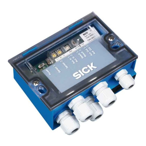
SICK FLPS Series User manual

OPERATING INSTRUCTIONS
Installation
Operation
Maintenance
Front page
FLPS Multibarrier

2 FLPS Multibarrier · Operating Instructions · 8021769/V1-0/2018-03 · © SICK Engineering GmbH
Document information
Product
Product name: FLPS Multibarrier
Document ID
Title: Operating Instructions FLPS Multibarrier
Part No.: 8021769
Version: 1-0
Release: 2018-03
Manufacturer
SICK Engineering GmbH
Bergener Ring 27 · D-01458 Ottendorf-Okrilla · Germany
Phone: +49 35205 52410
Fax: +49 35205 52450
E-mail: [email protected]
Original documents
The English version 8021769 of this document is an original
document from SICK Engineering GmbH.
SICK Engineering GmbH assumes no liability for the correctness of
an unauthorized translation.
Please contact SICK Engineering GmbH or your local representative
in case of doubt.
Legal information
Subject to change without notice.
© SICK Engineering GmbH. All rights reserved.
Warning symbols
Warning levels / Signal words
DANGER
Risk or hazardous situation which will result in severe personal
injury or death.
WARNING
Risk or hazardous situation which could result in severe personal
injury or death.
CAUTION
Hazard or unsafe practice which could result in less severe or
minor injuries.
NOTICE
Hazard which could result in material damage.
Information symbols
Hazard (general)
Voltage Hazard
Important technical information for this product

Contents
FLPS Multibarrier · Operating Instructions · 8021769/V1-0/2018-03 · © SICK Engineering GmbH 3
1 About this document . . . . . . . . . . . . . . . . . . . . . . . . . . . . . . . . . . . . . . . . . . . . . . . . . 5
1.1 Function of this document . . . . . . . . . . . . . . . . . . . . . . . . . . . . . . . . . . . . . . . . . . . . . . . . . . . . 6
1.2 Scope of application . . . . . . . . . . . . . . . . . . . . . . . . . . . . . . . . . . . . . . . . . . . . . . . . . . . . . . . . . 6
2Foryoursafety. . . . . . . . . . . . . . . . . . . . . . . . . . . . . . . . . . . . . . . . . . . . . . . . . . . . . . . . . 7
2.1 Intended use . . . . . . . . . . . . . . . . . . . . . . . . . . . . . . . . . . . . . . . . . . . . . . . . . . . . . . . . . . . . . . . . 8
2.1.1 Purpose of the device . . . . . . . . . . . . . . . . . . . . . . . . . . . . . . . . . . . . . . . . . . . . . . . . . . . . . . 8
2.1.2 Correct use . . . . . . . . . . . . . . . . . . . . . . . . . . . . . . . . . . . . . . . . . . . . . . . . . . . . . . . . . . . . . . . 8
2.2 Basic safety information . . . . . . . . . . . . . . . . . . . . . . . . . . . . . . . . . . . . . . . . . . . . . . . . . . . . . . 8
2.2.1 Hazards with electrical equipment . . . . . . . . . . . . . . . . . . . . . . . . . . . . . . . . . . . . . . . . . . 8
2.2.2 Operation in potentially explosive atmospheres . . . . . . . . . . . . . . . . . . . . . . . . . . . . . . 8
2.3 Requirements on the personnel's qualification . . . . . . . . . . . . . . . . . . . . . . . . . . . . . . . . . 9
2.4 Restrictions of use . . . . . . . . . . . . . . . . . . . . . . . . . . . . . . . . . . . . . . . . . . . . . . . . . . . . . . . . . . . 9
3 Product Description . . . . . . . . . . . . . . . . . . . . . . . . . . . . . . . . . . . . . . . . . . . . . . . . . 11
3.1 Product Identification . . . . . . . . . . . . . . . . . . . . . . . . . . . . . . . . . . . . . . . . . . . . . . . . . . . . . . . 12
3.2 Design and function . . . . . . . . . . . . . . . . . . . . . . . . . . . . . . . . . . . . . . . . . . . . . . . . . . . . . . . . 14
3.3 Device versions . . . . . . . . . . . . . . . . . . . . . . . . . . . . . . . . . . . . . . . . . . . . . . . . . . . . . . . . . . . . . 15
3.4 Interfaces . . . . . . . . . . . . . . . . . . . . . . . . . . . . . . . . . . . . . . . . . . . . . . . . . . . . . . . . . . . . . . . . . . 15
3.4.1 Communication via Modbus TCP . . . . . . . . . . . . . . . . . . . . . . . . . . . . . . . . . . . . . . . . . . . 15
3.4.2 Service access via USB . . . . . . . . . . . . . . . . . . . . . . . . . . . . . . . . . . . . . . . . . . . . . . . . . . . 15
3.5 Displays . . . . . . . . . . . . . . . . . . . . . . . . . . . . . . . . . . . . . . . . . . . . . . . . . . . . . . . . . . . . . . . . . . . 16
4 Installation . . . . . . . . . . . . . . . . . . . . . . . . . . . . . . . . . . . . . . . . . . . . . . . . . . . . . . . . . . . . 17
4.1 Safety Information . . . . . . . . . . . . . . . . . . . . . . . . . . . . . . . . . . . . . . . . . . . . . . . . . . . . . . . . . . 18
4.2 Mounting . . . . . . . . . . . . . . . . . . . . . . . . . . . . . . . . . . . . . . . . . . . . . . . . . . . . . . . . . . . . . . . . . . 19
4.3 Electrical Installation . . . . . . . . . . . . . . . . . . . . . . . . . . . . . . . . . . . . . . . . . . . . . . . . . . . . . . . . 19
4.3.1 Cable specification . . . . . . . . . . . . . . . . . . . . . . . . . . . . . . . . . . . . . . . . . . . . . . . . . . . . . . . 19
4.3.2 Connection parameters . . . . . . . . . . . . . . . . . . . . . . . . . . . . . . . . . . . . . . . . . . . . . . . . . . . 19
4.3.3 Connecting the FLPS Multibarrier . . . . . . . . . . . . . . . . . . . . . . . . . . . . . . . . . . . . . . . . . . 22
4.3.4 FO/DO configuration switches (Open Collector - Namur) . . . . . . . . . . . . . . . . . . . . . . 23
4.3.5 Termination of the RS485 interface . . . . . . . . . . . . . . . . . . . . . . . . . . . . . . . . . . . . . . . . 24
4.3.6 Connecting the interfaces . . . . . . . . . . . . . . . . . . . . . . . . . . . . . . . . . . . . . . . . . . . . . . . . . 24
4.3.7 Connection diagrams . . . . . . . . . . . . . . . . . . . . . . . . . . . . . . . . . . . . . . . . . . . . . . . . . . . . . 25
4.4 Function check . . . . . . . . . . . . . . . . . . . . . . . . . . . . . . . . . . . . . . . . . . . . . . . . . . . . . . . . . . . . . 27
5Troubleshooting. . . . . . . . . . . . . . . . . . . . . . . . . . . . . . . . . . . . . . . . . . . . . . . . . . . . . . 29
5.1 Replacing the fuse . . . . . . . . . . . . . . . . . . . . . . . . . . . . . . . . . . . . . . . . . . . . . . . . . . . . . . . . . . 30
5.2 Malfunction . . . . . . . . . . . . . . . . . . . . . . . . . . . . . . . . . . . . . . . . . . . . . . . . . . . . . . . . . . . . . . . . 30
5.3 Error rates . . . . . . . . . . . . . . . . . . . . . . . . . . . . . . . . . . . . . . . . . . . . . . . . . . . . . . . . . . . . . . . . . 30
6 Specifications . . . . . . . . . . . . . . . . . . . . . . . . . . . . . . . . . . . . . . . . . . . . . . . . . . . . . . . . . 31
6.1 Technical data . . . . . . . . . . . . . . . . . . . . . . . . . . . . . . . . . . . . . . . . . . . . . . . . . . . . . . . . . . . . . 32
6.2 Dimensional drawings . . . . . . . . . . . . . . . . . . . . . . . . . . . . . . . . . . . . . . . . . . . . . . . . . . . . . . . 32
6.3 Conformities . . . . . . . . . . . . . . . . . . . . . . . . . . . . . . . . . . . . . . . . . . . . . . . . . . . . . . . . . . . . . . . 33
6.4 Disposal . . . . . . . . . . . . . . . . . . . . . . . . . . . . . . . . . . . . . . . . . . . . . . . . . . . . . . . . . . . . . . . . . . . 33
Contents

Contents
4 FLPS Multibarrier · Operating Instructions · 8021769/V1-0/2018-03 · © SICK Engineering GmbH

6 FLPS Multibarrier · Operating Instructions · 8021769/V1-0/2018-03 · © SICK Engineering GmbH
About this document
Subject to change without notice
1.1 Function of this document
These Operating Instructions describe:
●Device components
●Installation
●Operation
●Maintenance work required for reliable operation
Retention of documents
▸
Keep these Operating Instructions and all associated documents available for
reference.
▸
Pass the documents on to a new owner.
1.2 Scope of application
These Operating Instructions cover standard applications which conform with the technical
data specified. Additional information and assistance for special applications are available
from your SICK representative. It is generally recommended to take advantage of qualified
consulting services provided by SICK experts for your specific application.

8 FLPS Multibarrier · Operating Instructions · 8021769/V1-0/2018-03 · © SICK Engineering GmbH
For your safety
Subject to change without notice
2.1 Intended use
2.1.1 Purpose of the device
The FLPS Multibarrier is a multichannel feed and input isolator amplifier to provide
intrinsically safe installation of FLOWSIC gas measuring devices.
2.1.2 Correct use
▸
Only use the FLPS Multibarrier as described in these Operating Instructions. The manu-
facturer bears no responsibility for any other use.
▸
Do not carry out any work or repairs on the FLPS Multibarrier not described in this man-
ual.
▸
Do not remove, add or change any components in or on the FLPS Multibarrier unless
such changes are officially allowed and specified by the manufacturer.
Failure to observe these precautions could result in:
– Any warranty by the manufacturer becomes void,
– causing the device to become dangerous,
– the approval for use in potentially explosive atmospheres is no longer valid.
▸
Do not use damaged components or parts.
Special local conditions
▸
Follow all local laws, regulations and company-internal operating directives applicable at
the installation location.
2.2 Basic safety information
▸
Only put the FLPS Multibarrier into operation after reading the Operating Instructions.
▸
Observe all safety information.
▸
If you do not understand something: Please contact SICK Customer Service.
2.2.1 Hazards with electrical equipment
2.2.2 Operation in potentially explosive atmospheres
▸
Install the device outside of hazardous areas only.
WARNING: Power voltage danger
▸
Disconnect the device from all effective power sources except the
intrinsically safe power circuits to the gas flow meter for installation,
maintenance and service work.
▸
Decommission the device when it is damaged, has been improperly loaded
or stored, or shows malfunctions.
WARNING: Risk of explosion
The FLPS Multibarrier is an [Ex ia] associated equipment that provides intinsi-
cally safe wiring with intinsicallay safe devices installed in Zone 1 or Zone 0.
▸
Substitution of components may impair Intrinsic Safety.

For your safety
FLPS Multibarrier · Operating Instructions · 8021769/V1-0/2018-03 · © SICK Engineering GmbH 9
Subject to change without notice
2.3 Requirements on the personnel's qualification
Designated users
The FLPS Multibarrier may only be installed and operated by skilled technicians who, based
on their technical training and knowledge as well as knowledge of the relevant regulations,
can assess the tasks given and recognize the hazards involved. Technicians must be skilled
according to DIN VDE 0105 or IEC 364 or directly comparable standards.
The named persons must have exact knowledge of operational hazards caused e.g. by hot,
toxic, explosive gases or gases under pressure, gas-liquid mixtures or other media as well
as adequate knowledge of the measuring system gained through training.
Specific requirements for use of devices in hazardous areas
2.4 Restrictions of use
▸
The degree of protection IP20 (IEC 60529/EN 60529) of the device is designed for a
clean and dry environment (degree of contamination 2 according to IEC 60664-1). Do
not submit the device to mechanical and/or thermal stress which exceeds the
described limits.
▸
The device meets the radio interference protection regulations (EMC) for the industrial
area (EMC class A). Use in living areas can lead to radio interference.
▸
Cabling /installation, device set-up, maintenance and check may be only
carried out by experienced personnel which has knowledge about the rules
and regulations for hazardous areas, in particular:
– type of protection
–installationrules
–areadefinition
▸
Regulations to be applied:
– EN/IEC 60079-11
– EN/IEC 60079-14
or comparable national regulations.

10 FLPS Multibarrier · Operating Instructions · 8021769/V1-0/2018-03 · © SICK Engineering GmbH
For your safety
Subject to change without notice

12 FLPS Multibarrier · Operating Instructions · 8021769/V1-0/2018-03 · © SICK Engineering GmbH
Product Description
Subject to change without notice
3.1 Product Identification
Type plate
The type plates is located on the module enclosure for information on identification of the
device.
Figure 1 Type plate (example)
Product name: FLPS Multibarrier
Manufacturer
SICK Engineering GmbH
Bergener Ring 27
D-01458 Ottendorf-Okrilla
Germany
SICK Engineering GmbH
Bergener Ring 27
01458 Ottendorf-Okrilla
Ge r m a ny
WARNING: Explosion Hazard
Read Operation Instructions before Installation.
Install per drawing no. 9275353
ADVERTENCIA: ameaça de explosão
Leia modos de aplicação antes de instalar.
Instale por documento no. 9275353
AVERTISSEMENT: Risque d'explosion
Lisez les modes d´emploi avant I´installation.
Installez par le dessin pas. 9275353
4098018
Tamb
Um=30VAC;60VDC
Power Supply (- Vin +):
SELV 10,8...26,4 V DC; max. 0.4 A
-40°C...+60°C
II (1)G [Ex ia Ga] IIC
FTZU 18 ATEX 0008X
FLPS2-60042-S-5
SICK Engineering GmbH
Bergener Ring 27
01458 Ottendorf-Okrilla
Ge r m a ny
WARNING: Explosion Hazard
Read Operation Instructions before Installation.
Install per drawing no. 9275353
AVERTISSEMENT: Risque d'explosion
Lisez les modes d´emploi avant I´installation.
Installez par le dessin pas. 9275353
ADVERTENCIA: ameaça de explosão
Leia modos de aplicação antes de instalar.
Instale por documento no. 9275353
4098018
Tamb
Um=30VAC;60VDC
Power Supply (- Vin +):
SELV 10,8...26,4 V DC; max. 0.4 A
-40°C...+60°C
II (1)G [Ex ia Ga] IIC
FTZU 18 ATEX 0008X
FLPS2-6004E-S-5
FLPS2-60042-S-5 FLPS2-6004E-S-5

Product Description
FLPS Multibarrier · Operating Instructions · 8021769/V1-0/2018-03 · © SICK Engineering GmbH 13
Subject to change without notice
Model name
Figure 2 Model name
FLPS 2 - 600 42 - S - 5
Product Name
Product Name FLPS
Device Type
Double Module 2
Separation
Device Family
FLOWSIC600 / XT / DRU / 60 600
Data interfaces
4*DO, 2*RS485 42
4*DO, 1*Ethernet, 1*RS485 4E
Separation
-
Ex classification
Safe zone S
Separation
-
Nominal supply voltage
5…15 V DC 5

14 FLPS Multibarrier · Operating Instructions · 8021769/V1-0/2018-03 · © SICK Engineering GmbH
Product Description
Subject to change without notice
3.2 Design and function
The FLPS Multibarrier is a multichannel feed and input isolator amplifier for the electrically
isolated operation of FLOWSIC600-XT gas measuring devices and the power source (intrin-
sically safe supply).
The device supplies the gas measuring device with voltage and allows the connection via
one or two serial as well as four digital interfaces, depending on the device version.
All interfaces are electrically isolated.
The serial interfaces are typically designed as RS485. Here, one can be used for connec-
tion to a volume converter and the second for connection to a higher level system or it can
be used as service interface via integrated mini USB 2.0 interface.
Figure 3 Overview FLPS Multibarrier
5
1 Screw terminals 5 DIL switches
2 Ethernet connection
(Model FLPS2-6004E-S-5)
6 Latch foot for fitting on the mounting rail
3 USB connection 7 Fuse
4 Marking with status LEDs
3
1
4
2
6
7

Product Description
FLPS Multibarrier · Operating Instructions · 8021769/V1-0/2018-03 · © SICK Engineering GmbH 15
Subject to change without notice
3.3 Device versions
The FLPS Multibarrier is available in two standard device versions:
Table 1 FLPS Multibarrier device versions
3.4 Interfaces
3.4.1 Communication via Modbus TCP
The device version FLPS2-6004E-S-5 is equipped with an Ethernet interface with data pro-
tocol Modbus TCP.
3.4.2 Service access via USB
Both device versions FLPS2-60042-S-5 and FLPS2-6004E-S-55 are equipped with a mini
USB 2.0 interface.
Part number Model name Description
2098122 FLPS2-60042-S-5
FLPS Multi Barrier FLPS2-60042-S-5
Multi-channel power and input isolating amplifier for
intrinsically safe installation of FLOWSIC600/-XT family
devices
– DIN-rail housing NS35: 45x114.5x99mm
– 4 digital I/O (puls/status)
– 2 serial I/O (RS485)
– 1 mini USB 2.0 Service I/O
2098136 FLPS2-6004E-S-5
FLPS Multi Barrier FLPS2-6004E-S-5
Multi-channel power and input isolating amplifier for
intrinsically safe installation of FLOWSIC600/-XT family
devices
– DIN-rail housing NS35: 45x114.5x99mm
– 4 digital I/O (puls/status)
– 1 serial I/O (RS485)
–1EthernetI/O
– 1 mini USB 2.0 Service I/O

16 FLPS Multibarrier · Operating Instructions · 8021769/V1-0/2018-03 · © SICK Engineering GmbH
Product Description
Subject to change without notice
3.5 Displays
●LED –“red” signals an error of the power supply (failure of fuse)
●LED –“blue” for intrinsically safe supply of the flow meter
●LED –“blue” for intrinsically safe supply of the RS485, from the flow meter
●LED –“green” for RS485 TX
●LED –“yellow” for RS485 RX
●x LED –“green” digital outputs
Figure 4 Displays
)O.0
)O.1
DO.3
2b 2a
DO.2
Vcl/Vout
1b 1a
RX2/TX2
RX1/TX1
Vaux
Fuse
failed
FLPS2-60042-S-5
-FI.1+ -+
-FI.0+ 2B 2A
-DI.3+ -+
-DI.2+ 1B 1A
-FO.0+-FO.1+
-DO.2+
-DO.3+ 1b 1a
2b 2a
PartNo.20981
FO.0
DO.3
DO.2
FO.1
2b 2a
Ethernet
RX2/TX2
RX1/TX1
Vaux
Fuse
failed
FLPS2-6004E-S-5
-FI.1+ -FI.0+ -+ 2B 2A
-DI.3+ -DI.2+ -+ 1B 1A
-FO.1+ -FO.0+
-DO.3+ -DO.2+
2b 2a
Vcl/Vout
Part No. 2098136
FLPS2-60042-S-5 FLPS2-6004E-S-5

18 FLPS Multibarrier · Operating Instructions · 8021769/V1-0/2018-03 · © SICK Engineering GmbH
Installation
Subject to change without notice
4.1 Safety Information
▸
Disconnect the device from all effective power sources except the intrinsically safe
power circuits to the gas flow meter for installation, maintenance and service work.
▸
Install the device outside of hazardous areas only.
▸
Provide a switch/circuit breaker near the device and mark it as disconnecting device for
this device (or the whole control cabinet).
▸
Provide an overcurrent protective device (I ≤16 A) during assembly.
▸
The enclosure of the device provides an ingress protection degree of IP20 according to
IEC/EN60529 and is suitable for indoor installation only. If required this device is to be
installed in an addional enclosure suitable for the exicting environmental conditions.
Outdoor installion requires IP54 or higher.
▸
In particular for interconnection with a device in Zone 0 the requirements in IEC/EN
60079-14 have to be observed.
▸
For safe operation connect the grounding terminal of the device with the potential
equalization (PE). All intrinsically safe circuits of the FLPS Multibarrier must be consid-
ered as grounded circuits.
▸
Two (2) connectors with a cross-section of minimum 1.5 mm² up to maximum 2.5 mm²
(stranded/ rigid ) are recommended to connect the ground terminal. Alternatively a sin-
gle stranded wire with a cross-section of 4 mm² only with a crimping cable lug may be
used.
▸
Conductors with a minimum cross-section of 0.2 mm² and a maximum cross-section
of 2.5 mm² (fine-stranded/rigid) may be connected to the connection terminals. The
tightening torque is 0.5 – 0.8 Nm. In case of stranded wires use wire end ferrules.
▸
Connect the device only to equipment, which does not carry voltage higher than 30 V AC
or 60 V DC peak. Use SELV power supplies and equipment that meets the rquirements
of IEC/EN 60950 or IEC/EN 61010-1.
▸
The safety-related technical values of the connected field devices must be conform with
the specifications of the Data Sheet and/or the EU Type Examination Certificate.
▸
Interconnection of several active operating resources in an intrinsically safe circuit may
result in different safety-related technical values. This can endanger the intrinsic safety!
The intrinsically safe RS485 interface of the FLPS Multibarrier is only permissible for
point to point connections. Connection to a FISCO system is not permitted.
▸
Modifications and alterations on the device are not permitted.
▸
Only install and operate the device in an undamaged, dry and clean state.
▸
When the device is not used according to the documentation, the designated protection
can be impaired.
WARNING: Risk of explosion
When the device is used in non-intrinsically safe power circuits, it no longer
may be used in intrinsically safe power circuits.
▸
Then, clearly mark the device as non-intrinsically safe.

Installation
FLPS Multibarrier · Operating Instructions · 8021769/V1-0/2018-03 · © SICK Engineering GmbH 19
Subject to change without notice
4.2 Mounting
▸
DIL switches are installed on the side of the enclosure for setting the termination of the
RS485 interface in the safe area . If required, set it prior to installation on the mounting
rail as described in →p. 24, §4.3.5. Termination to the gas flow meter is set fixed.
▸
Mount the FLPS Multibarrier on a 35 mm mounting rail (hat rail) according to EN
60715.
4.3 Electrical Installation
4.3.1 Cable specification
Cables and terminals
4.3.2 Connection parameters
Electrical isolation
▸
All connections to the safe area are isolated from the intrinsically safe connection and
ground.
▸
All intrinsically safe connections are not isolated from ground and must be connected to
the potential equalization (PE).
Input data for device supply
Parameters
Conductor cross section 0.5 … 2.5 mm² (20 … 12 AWG)
Cable type Conform with the requirements in the appropriate installation area
Maximum cable length to the gas
flow meter (twisted pair) 200 … 500 m (depending on the conductor cross-section)
Insulation stripping 7 mm
Tightening torque 0.5 … 0.8 Nm
Ethernet cable type Cat 5 or higher
Ethernet connector type RJ45
Maximum cable length (Ethernet) 100 m
USB connection Type mini USB 2.0
Parameters
Input/output/supply
Insulation voltage 500 Veff (1 min.)
Max. allowable voltage of the con-
nections in the safe area (rated
voltage)
30 V AC, 60 V DC
Connect the device only to equipment, which does not carry volt-
age higher than 30 V AC or 60 V DC peak. Use SELV power sup-
plies and equipment that meets the requirements of IEC/EN
60950 or IEC/EN 61010-1.
Symbol Parameters Min Type Max Unit
Vin Input voltage 10.8 24 26.4 V DC
Iin Input current 400 mA
PPowerinput 5W

20 FLPS Multibarrier · Operating Instructions · 8021769/V1-0/2018-03 · © SICK Engineering GmbH
Installation
Subject to change without notice
Connections in the safe area
Symbol Parameters Min Typical Max Unit
Switching outputs DO.1 … DO.4 (not intrinsically safe)
Uout Output voltage DO n/a n/a 30 VDC
Iout Output current DO 0.1 20 50 mA
Serial interfaces
RS485.1
(Alternative:
Ethernet)
Interface (not intrinsically safe) In accordance with standard EIA485
(In accordance with standard IEEE 802.3)
RS485.2 Interface (not intrinsically safe) In accordance with standard EIA485
Service interface (not intrinsically safe) –
designed as mini USB 2.0 In accordance with standard USB 2.0
This manual suits for next models
2
Table of contents
Other SICK Control Unit manuals

SICK
SICK CDM420-0004 User manual

SICK
SICK Flexi IO XTDO1 User manual

SICK
SICK CDF600-2200 User manual

SICK
SICK CDM420-0001 User manual

SICK
SICK CDM420-0006 User manual

SICK
SICK CDB650 User manual

SICK
SICK CDB730-001 User manual

SICK
SICK CDM420-0004 User manual

SICK
SICK CDB620 User manual

SICK
SICK SIM2000ST-E User manual