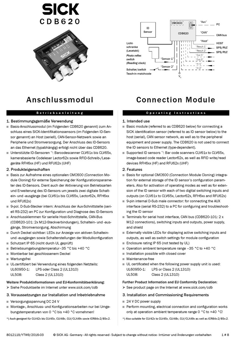
SICK UE10-3OS User manual

OPERATING INSTRUCTIONS
UE10-3OS
Expansion module for basic devices
SR-UE10

Contents
1 Ordering Information........................................................................ 3
2 Scope.................................................................................................. 4
3 On safety............................................................................................. 5
3.1 Skilled persons......................................................................................... 5
3.2 Field of use for the device........................................................................ 5
3.3 Intended use............................................................................................. 5
3.4 General safety instructions and protective measures........................... 6
3.5 Environmental protection......................................................................... 6
4 Product description........................................................................... 7
5 Mounting............................................................................................. 8
6 Electrical installation........................................................................ 9
7 Commissioning and regular tests................................................... 10
8 In the event of faults or errors......................................................... 11
9 Compliance with EU directives........................................................ 12
10 Internal circuitry................................................................................. 13
11 Technical specifications................................................................... 14
11.1 Data sheet................................................................................................. 14
11.2 Dimensional drawings.............................................................................. 16
CONTENTS
2O P E R A T I N G I N S T R U C T I O N S | UE10-3OS 8022191/2017-11-24 | SICK
Subject to change without notice

1 Ordering Information
Connection type Number of enable
current (N/O) con‐
tacts
Number of signalling
current (N/C) con‐
tacts
Number of contactor
monitoring (N/C)
contacts
Type Part number
Plug-in spring termi‐
nals
3 1 1 SR-UE10 1092502
ORDERING INFORMATION 1
8022191/2017-11-24 | SICK O P E R A T I N G I N S T R U C T I O N S | UE10-3OS 3
Subject to change without notice

2 Scope
These operating instructions are only applicable to the UE10-3OS basic device expan‐
sion modules with the following entry on the type label in the field Operating Instruc‐
tions: 8022170
You will find the device’s date of manufacture on the type label in the field Date Code in
the format yywwxxxx (yy = year, ww = calender week, xxxx = serial number).
These operating instructions are original operating instructions.
2 SCOPE
4O P E R A T I N G I N S T R U C T I O N S | UE10-3OS 8022191/2017-11-24 | SICK
Subject to change without notice

3 On safety
This chapter deals with your own safety and the safety of the equipment operators.
bPlease read this chapter carefully before working with the UE10-3OS or with the
machine protected by the UE10-3OS.
3.1 Skilled persons
The UE10-3OS expansion module must only be installed, commissioned and serviced
by qualified safety personnel.
Qualified safety personnel are defined as persons who …
•have undergone the appropriate technical training and
•have been instructed by the responsible machine operator in the operation of the
machine and the current valid safety guidelines and
•have access to the operating instructions of the expansion module and have read
and familiarised themselves with them.
3.2 Field of use for the device
The UE103OS expansion module can be used:
•in accordance with EN ISO 13 849 up to PL e and category 4
•in accordance with EN 62 061 to SILCL3
•in accordance with IEC 61 508 up to SIL3
The actual performance level or SIL claim limit achieved depends on the external cir‐
cuit, the design of the wiring, the selection of the control switch and its placement on
the machine.
The UE10-3OS expansion module has been evaluated to UL 508.
The UE10-3OS expansion module is used for:
•electro-sensitive protective equipment (ESPE) with monitored active output signal
switching device (OSSD): single-channel, dual-channel (in accordance with
IEC 61 4961)
•safety devices with monitored semiconductor outputs, e.g. Flexi Classic and Flexi
Soft
The UE10-3OS has no restart interlock and no external device monitoring.
3.3 Intended use
The UE103OS expansion module must be used only as defined in section "Field of use
for the device", page 5 .
It must be used only by qualified safety personnel and only on the machine where it has
been installed and initialised by qualified safety personnel in accordance with the oper‐
ating instructions. If the device is used for any other purposes or modified in any way —
also during mounting and installation — any warranty claim against SICK AG shall
become void.
ON SAFETY 3
8022191/2017-11-24 | SICK O P E R A T I N G I N S T R U C T I O N S | UE10-3OS 5
Subject to change without notice

3.4 General safety instructions and protective measures
DANGER
Pay attention to the safety notes and protective measures!
Please observe the following items in order to ensure the correct use of the UE10-3OS
expansion module.
•During the mounting, installation and usage of the expansion module, observe the
standards and directives applicable in your country.
•The national/international rules and regulations apply to the installation, commis‐
sioning, use and periodic technical inspection of the expansion module, in particu‐
lar:
– Machinery Directive
– Work Equipment Directive
– EMC directive
– the accident prevention regulations and safety regulations
•Manufacturers and operators of the machine on which a expansion module is
used are responsible for obtaining and observing all applicable safety regulations
and rules.
•The tests must be carried out by qualified safety personnel or specially qualified
and authorised personnel and must be recorded and documented to ensure that
the tests can be reproduced and retraced at any time by third parties.
•The operating instructions must be made available to the operator of the machine
where the UE10-3OS is used.
•The machine operator is to be instructed in the use of the device by qualified
safety personnel and must be instructed to read the operating instructions.
3.5 Environmental protection
Disposal of unusable or irreparable devices must always occur in accordance with the
applicable country-specific waste-disposal regulations (e.g. European Waste Code
16 02 14).
3 ON SAFETY
6O P E R A T I N G I N S T R U C T I O N S | UE10-3OS 8022191/2017-11-24 | SICK
Subject to change without notice

4 Product description
The related actuators on the machine or system can be safely shut down using the
expansion module’s output signal switching contacts.
The switching of the semiconductor outputs on the upstream basic devices controls the
internal relays via the two separate input circuits. The enable current paths are used as
safe outputs. The signalling current path is not a safe output. The feedback current
path is used as external device monitoring for the monitoring by the basic device.
DANGER
In order to attain SIL3/PL e, connect the external device monitoring!
In order to reach SIL3/PL e, an external diagnosis with DC ≥ 99 % must be applied (i.e.
the external device monitoring must be connected).
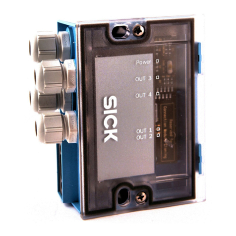
Table 1: Status indicators
Display Meaning
K1 O Green Channel 1 switched
K2 OGreen Channel 2 switched
PRODUCT DESCRIPTION 4
8022191/2017-11-24 | SICK O P E R A T I N G I N S T R U C T I O N S | UE10-3OS 7
Subject to change without notice

5 Mounting
DANGER
Mounting only with enclosure rating IP 54 or better!
The expansion module is only allowed to be mounted in the control cabinet. The control
cabinet must at least comply with enclosure rating IP 54.
bMounting in accordance with EN 50274.
bMounting on a 35 mm mounting rail (EN 60715).
5 MOUNTING
8O P E R A T I N G I N S T R U C T I O N S | UE10-3OS 8022191/2017-11-24 | SICK
Subject to change without notice

6 Electrical installation
NOTE
All external switching elements and their wiring must withstand an ampacity, maximal
short-circuit load of Imax = 1000 A (according to EN 60947-5-1).
DANGER
Switch the entire machine/system off line!
•The voltage supply must satisfy the regulations for extra-low voltages with safe iso‐
lation (SELV, PELV) for overvoltage category II as per EN 60 664 and EN 50 178.
NOTE
Overvoltage category III can be achieved if the contact circuits Y1/Y2 and 41/42 are
operated in the same circuit as the upstream OSSDs (safety extra-low voltage). For
installation in environments with overvoltage category III, external protection elements
must be used.
•All connections, wiring and cable runs must comply with the required category as
per EN ISO 13 849 and EN 62 061 (e.g. cables laid with protection, individually
sheathed cable with screen etc.).
•Always connect inputs B2 and B4 to the 0V potential of the supply voltage for the
basic devices.
•To protect the contact outputs on the and to increase the service life, the loads
connected must be equipped with, e.g., varistors and RC circuits. Please also note
that the selection of the arc suppression can increase the total response time of
the safety function.
•The output signal switching devices and the external device monitoring (EDM)
must be wired in the control cabinet.
•To prevent the welding of the contacts on the built-in relay, an overcurrent protec‐
tion device with max. 6 A short-circuit protection (duty class gG) is to be integrated
into the current paths (see figure 2, enable current path fuse F2/F3/F4).
Table 2: Pin assignments
Terminal Description
B1 Input circuit 1
B3 Input circuit 2
B2 0 V
B4 0 V
Y1-Y2 Feedback current path (for usage as external device monitoring)
13-14 Enable current path 1
23-24 Enable current path 2
33-34 Enable current path 3
41-42 Signalling current path (not safe)
Single-channel operation
A jumper is to be connected between B1 and B3. The semiconductor output on the
basic device is to be connected to B1; 0 V on the basic device is to be connected to the
contacts B2 and B4.
Dual-channel operation
The semiconductor outputs on the basic device are to be connected to B1 and B3; 0 V
on the basic device is to be connected to the contacts B2 and B4.
ELECTRICAL INSTALLATION 6
8022191/2017-11-24 | SICK O P E R A T I N G I N S T R U C T I O N S | UE10-3OS 9
Subject to change without notice
7 Commissioning and regular tests
DANGER
Commissioning requires a thorough check by qualified safety personnel!
Before you operate a system protected by the expansion module for the first time, make
sure that the system is first checked and released by qualified safety personnel.
bPlease read the notes in chapter "On safety", page 5.
bObserve the relevant laws and national regulations.
DANGER
Check the hazardous area!
bEnsure there is nobody in the hazardous area before commissioning.
bSecure the hazardous area against entry.
Regular inspection of the protective devices by qualified safety personnel
bCheck the system following the inspection intervals specified in the national rules
and regulations.
– Each safety application must be checked at an interval specified by you.
– The effectiveness of the protective devices must be checked daily by a spe‐
cialist or by authorised personnel.
bIf changes have been made to the machine or the protective device, or the expan‐
sion module has been changed or repaired, you must again thoroughly check the
entire safety application.
7 COMMISSIONING AND REGULAR TESTS
10 O P E R A T I N G I N S T R U C T I O N S | UE10-3OS 8022191/2017-11-24 | SICK
Subject to change without notice
8 In the event of faults or errors
DANGER
Cease operation if the cause of the malfunction has not been clearly identified!
bStop the machine if you cannot clearly identify or allocate the error and if you can‐
not safely rectify the malfunction.
DANGER
Complete function test after rectification of fault!
bAfter rectifying a fault, perform a complete function test.
IN THE EVENT OF FAULTS OR ERRORS 8
8022191/2017-11-24 | SICK O P E R A T I N G I N S T R U C T I O N S | UE10-3OS 11
Subject to change without notice
9 Compliance with EU directives
EU declaration of conformity (excerpt)
The undersigned, representing the following manufacturer herewith declares that the
product is in conformity with the provisions of the following EU directive(s) (including all
applicable amendments), and that the respective standards and/or technical specifica‐
tions are taken as the basis.
Complete EU declaration of conformity for download: www.sick.com
9 COMPLIANCE WITH EU DIRECTIVES
12 O P E R A T I N G I N S T R U C T I O N S | UE10-3OS 8022191/2017-11-24 | SICK
Subject to change without notice
10 Internal circuitry
Figure 1: Internal circuitry UE103OS
Figure 2: Basic circuit UE103OS
INTERNAL CIRCUITRY 10
8022191/2017-11-24 | SICK O P E R A T I N G I N S T R U C T I O N S | UE10-3OS 13
Subject to change without notice

11 Technical specifications
11.1 Data sheet
Minimum Typical Maximum
General system data
Safety integrity level1) SIL3 (IEC 61 508)
SIL claim limit SILCL3 (EN 62 061)
Safe failure fraction (SFF) 90 % (EN 62 061)
Hardware fault tolerance (HFT) 1 (EN 62 061)
Category Category 4 (EN ISO 13 849)
Performance Level PL e (EN ISO 13 849)
B10d value (relay)
AC15, 230 V, I = 1.5 A
AC15, 230 V, I = 0.75 A
DC13, 24 V, I = 2.5 A
DC13, 24 V, I = 0.63 A
1.26 × 10⁶ switching operations
5.9 × 10⁶ switching operations
435 × 103 switching operations
10 × 106 switching operations
PFHd (mean probability of a dangerous failure per
hour)2)
3 × 10⁻⁸
TM (mission time) 20 years (EN ISO 13 849)
Stop category 0/13) (EN 60 204-1)
Supply voltage/input circuit (B1-B2/B3-B4)
Input voltage (B1-B2/B3-B4), nominal voltage 24
V DC
15 V 24 V 30 V
For UL/CSA applications: Input voltage (B1-B2/B3-
B4)
24 V DC
Output current circuits > 25 V AC/60 V DC PELV at B1-B2/B3-B4
Output current circuits > 25 V AC/60 V DC SELV or PELV on B1-B2/B3-B4
Power consumption (total power) 2 × 1.2 W
Switch on current 500 mA
Power-up delay (B1-B2/B3-B4) 40 ms
Output current circuits (13/14, 23/24, 33/34, 41/42, Y1/Y2)
Reactivation delay K1/K2 (response time of the
protective function)
16 ms 20 ms
Contact material and surface finish Ag Sn O2 + 2 µm Au
Enable current paths (normally open contact),
safety relevant
3
Signalling current paths (normally closed contact),
not safety-relevant
1
Feedback current paths (normally closed contact,
external device monitoring)
1
Contact type Positively guided
Max. contact load, feedback current path (Y1, Y2)
Switching voltage DC 10 V 24 V
Switching current 5 mA 100 mA
1) For detailed information on the safety design of your machine/system, please contact your local SICK representative.
2) With DC = 99 % and MTTFd = 100 a (according to EN ISO 13 849, Tab. K1 and formula C.7) and 8760 switching operations/a.
3) Depending on the basic device, e.g. ESPE connected.
11 TECHNICAL SPECIFICATIONS
14 O P E R A T I N G I N S T R U C T I O N S | UE10-3OS 8022191/2017-11-24 | SICK
Subject to change without notice

Minimum Typical Maximum
Max. contact load (see diagram)
Switching voltage AC 10 V 230 V AC
Switching voltage DC 10 V 300 V DC
Switching current 5 mA 6 A
Total current 12 A
Usage category (EN 60 947-5-1) AC-15 Ue 230 V AC, Ie 4 A (360 switch‐
ing operations/h)
AC-15 Ue 230 V AC, Ie 3 A (3600
switching operations/h)
DC-13 Ue 24 V DC, Ie 4 A (360 switch‐
ing operations/h)
DC-13 Ue 24 V DC, Ie 2.5 A (3600
switching operations/h)
Contact fuse protection gG or circuit breaker with
characteristic B or C
6 A
Permissible switching frequency 3600/h
Service life, mechanical 107 switching operations
DC contact current-breaking capacity Service life, electrical
Switching current (A)
Switching voltage (V DC) Switching operations
Switching current (A)
AC-15: 230 V
AC-1: 230 V
DC-1: 24 V
DC-13: 24 V
Contact clearance:
1.2 mm
t
LB
: Arc duration
L/R = 40 ms
tLB > 5 ms
L/R = 40 ms
tLB < 5 ms
L/R = 0 ms
tLB < 5 ms
Operating data
Protection against physical contact (EN 60 6641,
EN 60 9471)
Rated impulse voltage VImp4 kV
Overvoltage category II4)
Rated voltage 300 V AC
Test voltage Urms 50 Hz 2 kV
Enclosure rating
Housing IP 40 (EN 60 529)
Terminals IP 20 (EN 60 529)
Mounting Mounting rail (EN 60 715)
Ambient operating temperature -25 °C +55 °C
Storage temperature -25 °C +75 °C
Wire cross-sections
Single wire (1×) 0.14 mm² 2.5 mm²
Single wire (2×, same cross-section) 0.14 mm² 0.75 mm²
Fine stranded wire with ferrules (1×) 0.25 mm² 2.5 mm²
4) To achieve overvoltage category III see note in chapter "Electrical installation", page 9.
TECHNICAL SPECIFICATIONS 11
8022191/2017-11-24 | SICK O P E R A T I N G I N S T R U C T I O N S | UE10-3OS 15
Subject to change without notice

Minimum Typical Maximum
Fine stranded wire with ferrules (2×, same cross-
section)
0.2 mm² 0.5 mm²
Radiated emissions EN 61 00064
Interference resistance EN 61 00062
Allowed tightening torque 0.5 Nm 0.6 Nm
For UL 508 and CSA applications
Connection cross-section AWG 26-14
(only use 60/75 °C copper flexible
wire)
Tightening torque 5-7 lb in
Weight 200 g
11.2 Dimensional drawings
107,6
78
58
93,3
96,5
93,7
22,5
75,3
114
5,1
14,8
5,1
14,8
109
89,8
71,3
Figure 3: Dimensional Drawing UE10-3OS with removable terminals
11 TECHNICAL SPECIFICATIONS
16 O P E R A T I N G I N S T R U C T I O N S | UE10-3OS 8022191/2017-11-24 | SICK
Subject to change without notice

Further locations at www.sick.com
Australia
Phone +61 3 9457 0600
1800 334 802 – tollfree
E-Mail [email protected]
Austria
Phone +43 22 36 62 28 8-0
E-Mail [email protected]
Belgium/Luxembourg
Phone +32 2 466 55 66
E-Mail info@sick.be
Brazil
Phone +55 11 3215-4900
E-Mail market[email protected]
Canada
Phone +1 905 771 14 44
E-Mail infor[email protected]
Czech Republic
Phone +420 2 57 91 18 50
E-Mail [email protected]
Chile
Phone +56 2 2274 7430
E-Mail info@schadler.com
China
Phone +86 20 2882 3600
E-Mail info[email protected]
Denmark
Phone +45 45 82 64 00
E-Mail [email protected]
Finland
Phone +358-9-2515 800
E-Mail [email protected]
France
Phone +33 1 64 62 35 00
E-Mail info@sick.fr
Germany
Phone +49 211 5301-301
E-Mail info@sick.de
Hong Kong
Phone +852 2153 6300
E-Mail [email protected]
Hungary
Phone +36 1 371 2680
E-Mail [email protected]
India
Phone +91 22 6119 8900
E-Mail info@sick-india.com
Israel
Phone +972 4 6881000
E-Mail info@sick-sensors.com
Italy
Phone +39 02 274341
E-Mail info@sick.it
Japan
Phone +81 3 5309 2112
E-Mail [email protected]
Malaysia
Phone +6 03 8080 7425
E-Mail enquiry[email protected]
Mexico
Phone +52 (472) 748 9451
E-Mail mario[email protected]
Netherlands
Phone +31 30 2044 000
E-Mail info@sick.nl
New Zealand
Phone +64 9 415 0459
0800 222 278 – tollfree
E-Mail [email protected]z
Norway
Phone +47 67 81 50 00
E-Mail [email protected]
Poland
Phone +48 22 539 41 00
E-Mail info@sick.pl
Romania
Phone +40 356 171 120
E-Mail [email protected]
Russia
Phone +7 495 775 05 30
E-Mail info@sick.ru
Singapore
Phone +65 6744 3732
E-Mail [email protected]
Slovakia
Phone +421 482 901201
E-Mail mail@sick-sk.sk
Slovenia
Phone +386 591 788 49
E-Mail [email protected]
South Africa
Phone +27 11 472 3733
E-Mail info@sickautomation.co.za
South Korea
Phone +82 2 786 6321
E-Mail info@sickkorea.net
Spain
Phone +34 93 480 31 00
E-Mail info@sick.es
Sweden
Phone +46 10 110 10 00
E-Mail info@sick.se
Switzerland
Phone +41 41 619 29 39
E-Mail [email protected]
Taiwan
Phone +886 2 2375-6288
E-Mail [email protected]
Thailand
Phone +66 2645 0009
E-Mail Ronnie[email protected]
Turkey
Phone +90 216 528 50 00
E-Mail info@sick.com.tr
United Arab Emirates
Phone +971 4 88 65 878
E-Mail info@sick.ae
United Kingdom
Phone +44 1727 831121
E-Mail info@sick.co.uk
USA
Phone +1 800 325 7425
E-Mail info@sick.com
Vietnam
Phone +84 945452999
E-Mail Ngo.Duy[email protected]
SICK AG | Waldkirch | Germany | www.sick.com
8022191/2017-11-24/en
Table of contents
Other SICK Control Unit manuals

SICK
SICK SIM2000ST-E User manual

SICK
SICK IOLG2PN-03208R01-PROFINET User manual

SICK
SICK CDB620 User manual

SICK
SICK CDF600-2200 User manual

SICK
SICK CDM420-0004 User manual

SICK
SICK ue10-30s User manual

SICK
SICK MSM Series User manual

SICK
SICK Flexi IO XTDO1 User manual

SICK
SICK CDB730-001 User manual

SICK
SICK IOLSHPB-P3104R01 User manual