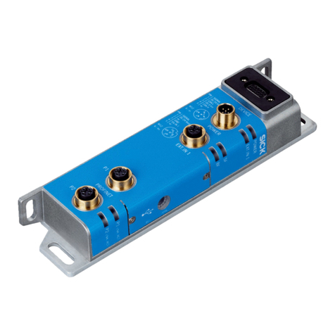
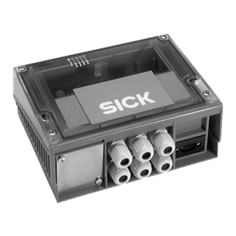
SICK CDB730-001 User manual

1 # 88014595/1GMK/2022-07 © SICK AG · Germany · All rights reserved · Subject to change without notice · Irrtümer und Änderungen vorbehalten
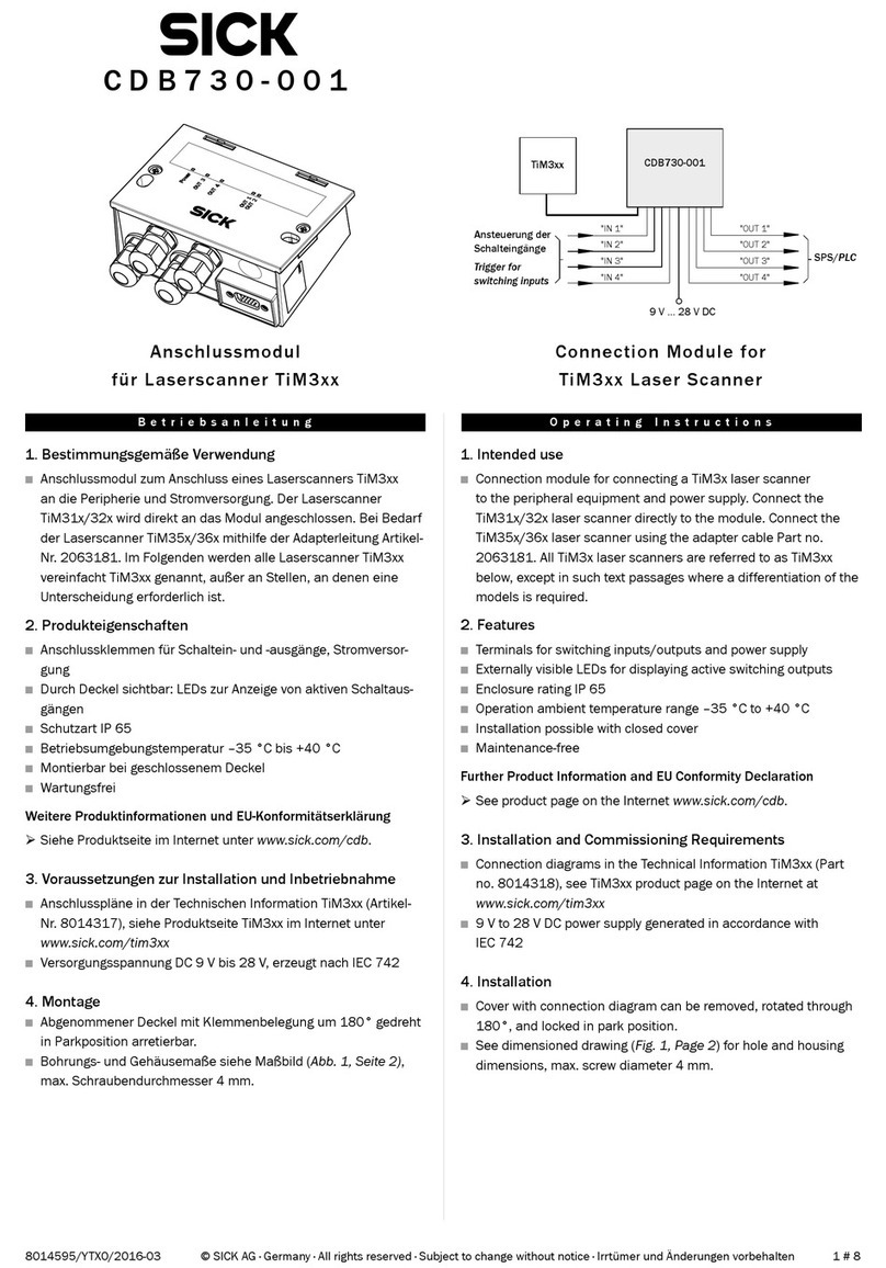
CDB730-001
1. Bestimmungsgemäße Verwendung
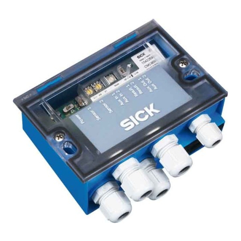
Das Anschlussmodul CDB730-001 dient zum Anschluss eines
2D-LiDAR-Sensors TiM3xx an die Peripherie und Stromversorgung.
Die Gerätetypen TiM31x/32x werden direkt an das Modul ange-
schlossen, die Gerätetypen TiM35x/36x mithilfe der Adapterleitung
Artikel-Nr. 2063181. Das Anschlussmodul kann nicht für Geräte
mit NPN-Digitaleingängen und -ausgängen (TiM3xx-10xxxxxS02)
verwendet werden!
2. Montage
• Abgenommener Deckel mit Klemmenbelegung um 180° gedreht
in Parkposition arretierbar.
• Bohrungs- und Gehäusemaße siehe Abb. 1, max. Schrauben-
durchmesser 4 mm.
Anschlussmodul
für 2D-LiDAR-Sensor TiM3xx-10xxxxx
Betriebsanleitung Operating Instructions
Connection Module for
2D LiDAR sensor TiM3xx-10xxxxx
OUT 1
OUT 2
OUT 3
OUT 4
Power
Alle Angaben in mm (inch)/All dimensions in mm (inch)
Abb. 1: Abmessungen des CDB730-001 / Fig. 1: Dimensions of the CDB730-001
1. Intended use
The connection module CDB730-001 is used to connect a
2D LiDAR sensor TiM3xx to the periphery and power supply. The
device types TiM31x/32x are connected directly to the module, the
device types TiM35x/36x are connected using the adapter cable
part no. 2063181. The connection module cannot be used for de-
vices with NPN digital inputs and outputs (TiM3xx-10xxxxxS02)!
2. Mounting
• Cover with connection diagram can be removed, rotated through
180°, and locked in park position.
• See Fig. 1 for hole and housing dimensions, max. screw diameter
4 mm.

2 # 8 8014595/1GMK/2022-07© SICK AG · Germany · All rights reserved · Subject to change without notice · Irrtümer und Änderungen vorbehalten
3. Kongurationselemente und Anzeigen
3.1 Funktion der Kongurationsschalter
3. Conguration Elements and Displays
3.1 Conguration Switches
3.2 Funktion der LEDs
LED Farbe Funktion
Power (UIN*) Grün Leuchtet, wenn die Versorgungsspannung am
CDB730-001 anliegt und Schalter S 1 auf „ON“
OUT 1, 2, 3, 4 Orange Leuchtet, wenn der entsprechende Ausgang des
TiM3xx schaltet
3.2 Function of LEDs
LED Color Function
Power (UIN*) Green Lights up when the power supply is connected
(UIN*) to the CDB730-001 and switch S 1 is set to "ON"
OUT 1, 2, 3, 4 Orange Lights up when the corresponding output of the
TiM3xx switches
Schalter Funktion Default
S 1 (Power) Anliegende Versorgungsspannung: ON
ON: Versorgungsspannung UIN* ein
OFF: Versorgungsspannung UIN* aus
S 3 (SGND-GND) Bezugspotenzial für Sensor-GND: ON
ON: Verbunden mit GND des Sensors (nicht
änderbar)
Switch Function Default
S 1 (Power) Power supply: ON
ON: Supply voltage UIN* on
OFF: Supply voltage UIN* off
S 3 (SGND-GND) Reference potential for sensor GND: ON (xed)
ON: Connected to sensor GND
4. Electrical Installation
4.1 Wiring notes
Risk of injuries due to electrical current!
If the supply voltage is provided by a power supply
unit, insufcient electrical insulation between input
and output circuit of the unit can cause an electric
shock.
Only use a power supply unit which output circuit is safely electri-
cally isolated from the input circuit by means of double insulation
and a safety isolating transformer according to IEC 742.
4. Elektrische Installation
4.1 Verdrahtungshinweise
Verletzungsgefahr durch elektrischen Strom!
Wird die Versorgungsspannung durch ein Netzteil
erzeugt, kann mangelhafte elektrische Trennung
zwischen Eingangs- und Ausgangskreis des Netzteils
zu einem Stromschlag führen.
WARNUNG
Nur ein Netzteil verwenden, dessen Ausgangskreis gegenüber
dem Eingangskreis eine sichere elektrische Trennung durch Dop-
pelisolation und Sicherheitstrafo nach IEC 742 besitzt.
WARNING
• Elektroinstallation nur durch ausgebildetes Fachpersonal durch-
führen.
• Bei Arbeiten in elektrischen Anlagen die gängigen Sicherheitsvor-
schriften beachten.
• Elektrische Verbindungen nur im spannungsfreien Zustand her-
stellen oder lösen.
• Die in der Betriebsanleitung des 2D-LiDAR-Sensors beschriebe-
nen "Voraussetzungen für den sicheren Betrieb" beachten!
• Klemmenbelegung siehe Anschlussbild im Deckel.
• Um Störeinüsse zu vermeiden, Leitungen möglichst nicht paral-
lel zu Stromversorgungs- und Motorleitungen verlegen.
1. Leitung des TiM31x/32x an die 15-pol. D-Sub-HD-Dose des
CDB730-001 anschließen. Für den TiM35x/36x mit 12-pol.
M12-Stecker die Adapterleitung Artikel-Nr. 2063181 verwenden.
2. Alle anderen Leitungen über Leitungsverschraubungen an den
Anschlussklemmen des CDB730-001 auegen.
3. Anwenderseitige Schirmung am CDB730-001 auegen (An-
schlussklemme „Shield“).
• Electrical installation should only be carried out by qualied staff.
• Observe the current safety regulations when working on electrical
systems.
• Connect or disconnect current linkages only under de-energized
conditions.
• Observe the "Prerequisites for safe operation" described in the
operating manual of the 2D LiDAR sensor!
• For terminal assignment see connection diagram inside the
cover.
• To prevent interference, do not lay cables parallel to power supply
or motor cables.
1. Connect the TiM31x/32x cable to the 15-pin D-Sub HD female
connector of the CDB730-001. For TiM35x/36x with 12-pin M12
male connector use the adapter cable part. no. 2063181.
2. Connect all other cables to the terminals of the CDB730-001
provided using cable glands.
3. Connect the shield of your system to the CDB730-001 ("Shield"
terminal).
3 # 88014595/1GMK/2022-07 © SICK AG · Germany · All rights reserved · Subject to change without notice · Irrtümer und Änderungen vorbehalten
4.2 Elektrisches Blockschaltbild / Electrical block diagram
“VS”
“OUT 2”
“OUT 1”
“USB (Aux)”
“IN 3”
“IN 2”
“IN 1”
“IN 4”
“OUT 4”
“OUT 3”
“OUT 2”
“OUT 1”
“OUT 4”
“OUT 3”
VS
“AUX”
CDB730-001
PC
Konfiguration,
Feldüberwachung
oder Diagnose
Configuration,
Field Monitoring
or Diagnostics
TiM3xx
Schnittstellen
Interfaces
“IN 3”
“IN 2”
“IN 1”
“IN 4”
Abb. 2: Anschluss TiM3xx über CDB730-001 an die Peripherie / Fig. 2: Connectiong TiM3xx via CDB730-001 to the periphery
Beschädigungsgefahr!
Geräte mit NPN-Digitaleingängen und -ausgängen
(TiM3xx-xxxxxxxxS02) nicht an das Anschlussmodul
CDB730-001 anschließen!
WICHTIG
Weitere Informationen zur Funktionalität der Digitaleingänge und
-ausgänge des Geräts siehe Betriebsanleitung des Geräts!
Risk of damage!
Do not connect devices with NPN digital inputs and outputs
(TiM3xx-xxxxxxxxS02) to the connection module CDB730-001!
IMPORTANT
For further information on the functionality of the digital inputs and
outputs of the device, refer to the operating manual of the device!

4 # 8 8014595/1GMK/2022-07© SICK AG · Germany · All rights reserved · Subject to change without notice · Irrtümer und Änderungen vorbehalten
4.3 Verdrahtungsübersicht / Wiring overview
ONOFF
ONOFF
POWER
S1
0.8 A T
SGND - GND
S3
10 11 12 13 14 15 16 17 18
OUT 3
UIN*
UIN*
OUT 4
SGND
SGND
nc
nc
SGND
LEDs
30 31 32 33 34
IN 3
IN 4
IN 1
nc
GND
40 41 42 43 44
nc
nc
nc
IN 2
GND
SCANNER
UIN
UIN
GND
GND
Shield
Shield
Shield
Shield
12345678
20 21 22 23 24
OUT 1
OUT 2
GND
nc
nc
F
*)
Ansteuerung der Digitaleingänge
Triggering of digital inputs
Ausgabe Feldverletzung oder Fehler
Output of field infringement or error
UIN*
OUT 1234GND IN 1234GND
-TiM3xx
110
15
6
11
5
VS
VS- UIN -
F S 1
- UIN*
Klemmen mit Bezeichnung "nc" (not connected) nicht belegen!
Do not wire terminals marked with “nc” (not connected)!
Abb. 3: Verdrahtungsübersicht CDB730-001 / Fig. 3: Wiring overview CDB730-001
4.4 Versorgungsspannung anschließen / Connecting the supply voltage
TiM3xx
CDB730-001
VS
VS
1
5
5Shield
1U
IN
2 GND
UIN*
GND
S1
F
Shield
GND
.
.
.
.
.
.
ON
OFF
S1 : POWER
UIN*
POWER
Vs
110
15
6
11
5
VS- UIN -
F S 1
- UIN*
Schalter S1
ON: Versorgungsspannung UIN über Sicherung
und Schalter S1 als Versorgungsspannung UIN*
an CDB730-001 und Gerät angeschlossen.
Versorgungsspannung UIN* zusätzlich an
Anschlussklemmen 11 und 14 abgreifbar.
OFF: CDB730-001 und Gerät von Versorgungs-
spannung getrennt.
Empfohlene Stellung bei allen Anschlussarbeiten.
Switch S1
ON: Power supply voltage UIN switched to UIN* via
fuse and switch S1 as Power supply voltage UIN*
to CDB730-001 and TiM3xx.
Power supply voltage UIN* additionally available
on terminals 11 and 14.
OFF: CDB730-001 and TiM3xx disconnected
from power supply voltage.
Recommended position during all electrical
installation work.
Abb. 4 Versorgungsspannung anschließen CDB730-001 / Fig. 4: Connectiong the supply voltage CDB730-001

5 # 88014595/1GMK/2022-07 © SICK AG · Germany · All rights reserved · Subject to change without notice · Irrtümer und Änderungen vorbehalten
4.5 Digitaleingänge beschalten / Wiring the digital inputs
TiM3xxCDB730-001
VS
VS
GND
INGND
3.32 K
6.64 K
IN 1
Vin
8
15
1
5
12 SGND
6Shield
11 UIN*
33 IN 1
UIN*
GND
S3
ON
OFF
S3 : SGND-GND
Shield
GND
.
.
.
Schaltelement durch
CDB730-001 versorgt
Control element supplied
via CDB730-001
Schema / Scheme:
Schaltelement extern
versorgt
Control element
supplied externally
GND
VS ext
110
15
6
11
5
IN 2
9
43 IN 2
IN 3
10
30 IN 3
IN 4
11
31 IN 4
Abb. 5: Digitaleingänge beschalten CDB730-001 / Fig. 5: Wiring the digital inputs CDB730-001
Funktion Schalter S3
Schalterstellung Funktion
ON Der gemeinsame Bezugspunkt SGND der
Digitaleingänge "IN 1" bis "IN 4" ist im
CDB730-001 dauerhaft mit GND des Geräts
verbunden. Damit sind die Digitaleingänge nicht
mehr von der Versorgungsspannung des Geräts
entkoppelt. Dies ist im CDB730-001 nicht
änderbar!
OFF Entfällt
Kenndaten Digitaleingänge IN1 … IN4
Typ Schaltend
Schaltverhalten Spannung auf den Digitaleingang aktiviert in
binärer Kombination mit den anderen Eingängen
den zugeordneten Feldsatz als Auswertfall.
Grundeinstellung im Gerät: Pegel aktiv high,
Entprellung 10 ms
Eigenschaften Verpolsicher
Mit PNP-Ausgang eines Trigger-Sensors oder
mit einem mechanischen Schalter beschaltbar.
Elektrische Werte Low: Vin ≤ 2 V; Iin ≤ 0,3 mA
High: 8 V ≤ Vin ≤ 32 V; 0,7 mA ≤ Iin ≤ 5 mA
Function switch S3
Switch position Function
ON The common reference point SGND of the digital
inputs "IN 1" to "IN 4" is permanently connected
to GND of the device in the connection module.
The digital inputs are therefore no longer
decoupled from the supply voltage of the device.
This cannot be changed in the CDB730-001!
OFF Not applicable
Ratings for digital inputs IN1 … IN4
Type Switching
Switching behavior Voltage fed to an input in combination with the
other inputs starts the assigned eld set as
evaluation case.
Default settings: active high level,
debouncing 10 ms
Features Reverse polarity protected
Can be wired with the PNP output of a trigger
sensor or with a mechanical switch.
Electrical values Low: Vin ≤ 2 V; Iin ≤ 0,3 mA
High: 8 V ≤ Vin ≤ 32 V; 0,7 mA ≤ Iin ≤ 5 mA

6 # 8 8014595/1GMK/2022-07© SICK AG · Germany · All rights reserved · Subject to change without notice · Irrtümer und Änderungen vorbehalten
4.6 Digitalausgänge beschalten / Wiring the digital outputs
Schema / Scheme:
TiM3xx CDB730-001 Load (e.g. PLC)
12
5
20OUT 1
22GND
5Shield
UIN*V S
GND
Vout
OUT 1
GND
1
14 10OUT 3
OUT 3
13 21OUT 2
OUT 2
413OUT 4
OUT 4
110
15
6
11
5
Bei induktiver Last eine Funkenlöschschaltung am Digitalausgang vorsehen.
Hierzu eine Freilaufdiode direkt an der Last anbringen.
Provide an arc-suppression circuit at the digital switching output if an inductive
load is present. Attach a freewheeling diode directly to the load for this purpose.
Abb. 6: Digitalausgänge beschalten CDB730-001 / Fig. 6: Wiring the digital outputs CDB730-001
Kenndaten Digitalausgänge OUT1 … OUT4
Typ Schaltend
Schaltverhalten PNP-schaltend gegen Versorgungsspannung VS
OUT 1 … OUT 3:
Ruhepegel: High (keine Feldverletzung)
Arbeitspegel: Low (Feldverletzung)
OUT 4:
Ruhepegel: High (Device Ready)
Arbeitspegel: Low (Fehler), Low-Impuls (15 Hz,
Index, entspricht Messung bei 90°)
Eigenschaften Kurzschlussfest und temperaturgeschützt
Galvanisch nicht getrennt von der Versorgungs-
spannung VS
Elektrische Werte 0 V ≤ Vout ≤ VS
(VS −1,5 V) ≤ Vout ≤ VSbei Iout ≤ 100 mA
Ratings for digital outputs OUT1 … OUT4
Type Switching
Switching behavior PNP switching against the supply voltage VS
OUT 1 … OUT 3:
Idle level: High (no eld infringement)
Working level: Low (eld infringement)
OUT 4:
Idle level: High (Device Ready)
Working level: Low (error), Low (15 Hz, Index,
corresponds to measurement at 90°)
Features Short-circuit proof + temperature protected
Galvanically not separate from VS
Electrical values 0 V ≤ Vout ≤ VS
(VS −1,5 V) ≤ Vout ≤ VSbei Iout ≤ 100 mA

7 # 88014595/1GMK/2022-07 © SICK AG · Germany · All rights reserved · Subject to change without notice · Irrtümer und Änderungen vorbehalten
5. Technische Daten
Typ CDB730-001 (Artikel-Nr. 1055981)
Optische Anzeigen 5 x LED
Elektrische Anschlüsse Dose, D-Sub-HD, 15-pol.
Federkraftklemmen:
8 für Adern 0,14 mm2...2,5 mm2
24 für Adern 0,14 mm2... 1 mm2
Leitungsverschraubungen 4 x M16, Klemmbereich ∅ 4,5 ... 10 (7) mm
Versorgungsspannung DC 9 V ... 28 V für TiM3xx, SELV bzw.
PELV nach IEC 60364-4-41
Eigenleistungsaufnahme < 0,5 W
Eingangsstrom Max. 2,4 A (an Anschlussklemme UIN)
Sicherung Glasrohrsicherung 0,8 A träge für UIN* 1)
Gehäuse/Farbe Polycarbonat/Grundteil lichtblau (nach RAL
5012), Deckel neutral/teildurchsichtig
Prüfzeichen CE
Elektrische Sicherheit IEC 61010-1:2010 + Cor.:2011
Schutzklasse III, nach EN 61140: 2007-03
Schutzart IP 65 2), nach EN 60529: 1999-10
EMV-Prüfung Störaussendung: nach EN 61000-6-3: 2007-
01/ A1: 2011-03
Störfestigkeit: nach EN 61000-6-2: 2005-08
Gewicht Ca. 240 g
Umgebungstemperatur Betrieb: –35 °C 3) ... +40 °C
Lager: –35 °C ... +70 °C
Rel. Luftfeuchtigkeit Max. 90 %, nicht kondensierend
1) Geschaltet über S 1.
2) Mit SICK Standardleitung für Sensoren.
3) Betriebsumgebungstemperatur 0 °C bis –35 °C bei folgenden Bedingungen:
– Montage, elektrischer Anschluss sowie Konguration und Power-up des Moduls
über eingebaute Schalter nur im normalen Betriebsumgebungtemperaturbereich
0 °C bis +40 °C.
– Einsatz nur im Zustand der Ruhe (keine Montage-, Anschluss- oder Kongura-
tionsarbeiten am Modul).
5. Technical Data
Type CDB730-001 (Part no. 1055981)
Visual indicators 5 x LEDs
Electrical connections Female connector, D-Sub HD, 15-pin
Spring terminals: 8 for cores 0.14 mm2 ...
2.5 mm2(approx. 26 to 13 AWG) and 24 for cores
0.14 mm2 ... 1 mm2 (approx. 26 to 17 AWG)
Cable glands 4 x M16, for cables ∅ 4.5 mm ... 10 (7) mm
Power supply 9 V to 28 V DC for TiM3xx, SELV respectively PELV
accord. to IEC 60364-4-41
Power consumption < 0.5 W (internal)
Input current Max. 2.4 A (on terminals UIN)
Fuse Glass tube fuse 0.8 A, slow-blow, for UIN* 1)
Housing/Color Polycarbonate/basic light blue (accord. to RAL
5012), cover neutral/partially transparent
Conformity CE
Electrical Safety IEC 61010-1:2010 + Cor.:2011
Protection class III, according to EN 61140: 2007-03
Enclosure rating IP 65 2), according to EN 60529: 1999-10
EMC tested Emission: according to EN 61000-6-3: 2007-01/
A1: 2011-03
Immunity: according to EN 61000-6-2: 2005-08
Weight Approx. 240 g
Ambient Operation: –35 °C 3) ... +40 °C
temperature Storage: –35 °C ... +70 °C
Rel. air humidity Max. 90%, non-condensing
1) Switched via S 1.
2) With SICK standard sensor cable.
3) Temperature range 0 °C to –35 °C at the following conditions:
– Installation, electrical connection as well as conguration and power-up of the
module using built-in switches only at normal operation ambient temperature
range of 0 °C to +40 °C.
– Application of the module only in rest status (without any mounting, electrical
installation or conguration works on the module).
Weitere Produktinformationen und EU-Konformitätserklärung
• Siehe Produktseite im Internet unter www.sick.com/CDB
Further Product Information and EU Conformity Declaration
• See product page on the Internet www.sick.com/CDB

8 # 8 8014595/1GMK/2022-07© SICK AG · Germany · All rights reserved · Subject to change without notice · Irrtümer und Änderungen vorbehalten
Australia
Phone +61 (3) 9457 0600
1800 33 48 02 – tollfree
E-Mail [email protected]
Austria
Phone +43 (0) 2236 62288-0
E-Mail [email protected]
Belgium/Luxembourg
Phone +32 (0) 2 466 55 66
E-Mail [email protected]
Brazil
Phone +55 11 3215-4900
E-Mail [email protected]
Canada
Phone +1 905.771.1444
E-Mail [email protected]
Czech Republic
Phone +420 234 719 500
E-Mail [email protected]
Chile
Phone +56 (2) 2274 7430
E-Mail [email protected]
China
Phone +86 20 2882 3600
E-Mail [email protected]t.cn
Denmark
Phone +45 45 82 64 00
E-Mail [email protected]
Finland
Phone +358-9-25 15 800
E-Mail [email protected]
France
Phone +33 1 64 62 35 00
E-Mail [email protected]
Germany
Phone +49 (0) 2 11 53 010
E-Mail [email protected]
Greece
Phone +30 210 6825100
E-Mail [email protected]
Hong Kong
Phone +852 2153 6300
E-Mail [email protected]
Hungary
Phone +36 1 371 2680
E-Mail ertekesites@sick.hu
India
Phone +91-22-6119 8900
E-Mail info@sick-india.com
Israel
Phone +972 97110 11
E-Mail info@sick-sensors.com
Italy
Phone +39 02 27 43 41
E-Mail [email protected]
Japan
Phone +81 3 5309 2112
E-Mail [email protected]
Malaysia
Phone +603-8080 7425
E-Mail enquiry.m[email protected]
Mexico
Phone +52 (472) 748 9451
E-Mail [email protected]
Netherlands
Phone +31 (0) 30 229 25 44
E-Mail [email protected]
New Zealand
Phone +64 9 415 0459
0800 222 278 – tollfree
E-Mail [email protected]
Norway
Phone +47 67 81 50 00
E-Mail [email protected]
Poland
Phone +48 22 539 41 00
E-Mail [email protected]
Romania
Phone +40 356-17 11 20
E-Mail [email protected]
Russia
Phone +7 495 283 09 90
E-Mail [email protected]
Singapore
Phone +65 6744 3732
E-Mail [email protected]
Slovakia
Phone +421 482 901 201
E-Mail [email protected]
Slovenia
Phone +386 591 78849
E-Mail [email protected]
South Africa
Phone +27 10 060 0550
E-Mail info@sickautomation.co.za
South Korea
Phone +82 2 786 6321/4
Spain
Phone +34 93 480 31 00
E-Mail [email protected]
Sweden
Phone +46 10 110 10 00
E-Mail [email protected]
Switzerland
Phone +41 41 619 29 39
E-Mail [email protected]
Taiwan
Phone +886-2-2375-6288
E-Mail [email protected]
Thailand
Phone +66 2 645 0009
E-Mail [email protected]
Turkey
Phone +90 (216) 528 50 00
E-Mail [email protected]
United Arab Emirates
Phone +971 (0) 4 88 65 878
E-Mail [email protected]
United Kingdom
Phone +44 (0)17278 31121
E-Mail [email protected]
USA
Phone +1 800.325.7425
E-Mail [email protected]
Vietnam
Phone +65 6744 3732
E-Mail [email protected]
Detailed addresses and further locations at www.sick.com
Table of contents
Other SICK Control Unit manuals

SICK
SICK UE10-3OS User manual

SICK
SICK IOLSHPB-P3104R01 User manual

SICK
SICK CDB730-001 User manual

SICK
SICK SIM2000ST-E User manual

SICK
SICK MSM Series User manual

SICK
SICK CDB620 User manual

SICK
SICK ue10-30s User manual

SICK
SICK CDB620 User manual

SICK
SICK CDM420-0004 User manual

SICK
SICK CDB620 User manual
Popular Control Unit manuals by other brands

AGFEO
AGFEO AS 40 Installation instruction

GEM
GEM 673 Installation, operating and maintenance instructions

Nice
Nice MC200 Instructions and warnings for installation and use

Audioplex
Audioplex VC300 installation manual

Siemens
Siemens SIMATIC ET 200SP manual

Moeller
Moeller XC-CPU101 Series Hardware description